
Create successful ePaper yourself
Turn your PDF publications into a flip-book with our unique Google optimized e-Paper software.
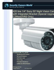
VIVOTEKInstallationHardware Installation1. Loo<strong>se</strong> the liquid tight connectors, and then remove the rubber.2. Loo<strong>se</strong> the back cover.3. Tear down the aluminum foil vacuum bag and take out the silica gel. Attach the supplied silicagel to the inner side of the Network Camera. (Plea<strong>se</strong> replace the silica gel with a new one ifyou open the back cover after installation.)4. Make sure all cable lines are <strong>se</strong>curely connected.5. Tighten the back cover, rubber and liquid tight connectors.6. Secure the Network Camera to the wall/ceiling by the supplied camera stand.2615Wall mountCeiling mount3Silica gelNoteIf you want to u<strong>se</strong> your own cable lines, plea<strong>se</strong> loo<strong>se</strong> two supplied screws and take out thepower board. Then be careful to make connections as the illustration below.Power CordUpper SideTerminal Block (from left to right)1: AV24V (red)2: AC24V (red)3: DI (white)4: GND (black)Ethernet CableScrewsBottom Side6 - <strong>U<strong>se</strong>r</strong>'s <strong>Manual</strong>
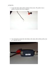
POWER CO LISION1 2 3 4 5LINKRECEIVEPARTITIONPOWER COLLISION1 2 3 4 5LINKRECEIVEPARTITIONVIVOTEKNetwork DeploymentSetup the Network Camera over the InternetThis <strong>se</strong>ction explains how to configure the Network Camera to Internet connection.1. If you have external devices such as <strong>se</strong>nsors and alarms, make the connection from thegeneral I/O terminal block.2. U<strong>se</strong> the supplied RJ45 female/female coupler to connect the Network Camera to a switch.U<strong>se</strong> Category 5 Cross Cable when Network Camera is directly connected to PC.3. Connect the power cable from the Network Camera to a power outlet.21AV24VAC24VDIGNDAV24V: 24V+AC24V: 24V-DI : Digital InputGND: Ground3There are <strong>se</strong>veral ways to <strong>se</strong>t up the Network Camera over the Internet. The first way is to <strong>se</strong>tup the Network Camera behind a router. The <strong>se</strong>cond way is to utilize a static IP. The third way isto u<strong>se</strong> PPPoE.Internet connection via a routerBefore <strong>se</strong>tting up the Network Camera over the Internet, make sure you have a router and followthe steps below.1. Connect your Network Camera behind a router, the Internet environment is illustrated below.Regarding how to obtain your IP address, plea<strong>se</strong> refer to Software installation on page 10 fordetails.InternetWAN (Wide Area Network )Router IP address : from ISPIP address : 192.168.0.3Subnet mask : 255.255.255.0Default router : 192.168.0.1LAN (Local Area Network)Router IP address : 192.168.0.1Cable or DSL ModemIP address : 192.168.0.2Subnet mask : 255.255.255.0Default router : 192.168.0.1<strong>U<strong>se</strong>r</strong>'s <strong>Manual</strong> - 7
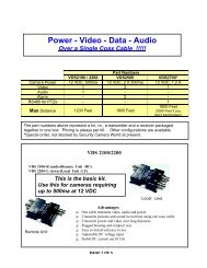
POWER COLLISION1 2 3 4 5LINKRECEIVEPARTITIONVIVOTEK2. In this ca<strong>se</strong>, if the Local Area Network (LAN) IP address of your Network Camera is192.168.0.3, plea<strong>se</strong> forward the following ports for the Network Camera on the router.■ HTTP port■ RTSP port■ RTP port for audio■ RTCP port for audio■ RTP port for video■ RTCP port for videoIf you have changed the port numbers on the Network page, plea<strong>se</strong> open the ports accordinglyon your router. For information on how to forward ports on the router, plea<strong>se</strong> refer to yourrouter’s u<strong>se</strong>r’s manual.3. Find out the public IP address of your router provided by your ISP (Internet Service Provider).U<strong>se</strong> the public IP and the <strong>se</strong>condary HTTP port to access the Network Camera from theInternet. Plea<strong>se</strong> refer to Network Type on page 30 for details.Internet connection with static IPChoo<strong>se</strong> this connection type if you are required to u<strong>se</strong> a static IP for the Network Camera.Plea<strong>se</strong> refer to LAN on page 30 for details.Internet connection via PPPoE (Point-to-Point over Ethernet)Choo<strong>se</strong> this connection type if you are connected to the Internet via a DSL Line. Plea<strong>se</strong> refer toPPPoE on page 31 for details.Set up the Network Camera through Power over Ethernet (PoE)When using a PoE-enabled switchThe Network Camera is PoE-compliant, which allows it to be powered via a single Ethernetcable. If your switch/router supports PoE, refer to the following illustration to connect theNetwork Camera to a PoE-enabled switch/router.power + data transmissionPoE Switch8 - <strong>U<strong>se</strong>r</strong>'s <strong>Manual</strong>
VIVOTEKSoftware InstallationInstallation Wizard 2 (IW2), free-bundled software included on the product CD, helps you <strong>se</strong>t upyour Network Camera on the LAN.1. Install IW2 from the Software Utility directory on the software CD.Double click the IW2 shortcut on your desktop to launch the program.2. The program will conduct an analysis of your network environment.After your network environment is analyzed, plea<strong>se</strong> click Next to continue the program.3. The program will <strong>se</strong>arch for all VIVOTEK network devices on the same LAN.4. After <strong>se</strong>arching, the main installer window will pop up. Click on the MAC and model namewhich matches the product label on your device to connect to the Network Camera viaInternet Explorer.Network CameraModel No: IP7330 RoHSMAC:0002D1733012This device complies with part 15 of the FCC rules. Operation is subject to the following two conditions:(1)This device may not cau<strong>se</strong> harmful interference, and(2) this device must accept any interference received, including interference that may cau<strong>se</strong> undesired operation.Pat. 6,930,709Made in Taiwan0002D173301210 - <strong>U<strong>se</strong>r</strong>'s <strong>Manual</strong>
VIVOTEKAccessing the Network CameraThis chapter explains how to access the Network Camera through web brow<strong>se</strong>rs, RTSP players,3GPP-compatible mobile devices, and VIVOTEK recording software.Using Web Brow<strong>se</strong>rsU<strong>se</strong> Installation Wizard 2 (IW2) to access to the Network Cameras installed on the LAN.If your network environment is not a LAN, follow the<strong>se</strong> steps to access the Network Camera:1. Launch your web brow<strong>se</strong>r (ex. Microsoft ® Internet Explorer, Mozilla Firefox, or Netscape).2. Enter the IP address of the Network Camera in the address field. Press Enter.3. The live video will be displayed in your web brow<strong>se</strong>r.4. If this is the first time installing the VIVOTEK network camera, an information bar will pop upas shown below. Follow the instructions to install the required plug-in on your computer.NOTE► For Mozilla Firefox or Netscape u<strong>se</strong>rs, your brow<strong>se</strong>r will u<strong>se</strong> Quick Time to stream the livevideo. If you donn’t have Quick Time on your computer, plea<strong>se</strong> install it first, then launch theweb brow<strong>se</strong>r.<strong>U<strong>se</strong>r</strong>'s <strong>Manual</strong> - 11
VIVOTEK► By default, the Network Camera is not password-protected. To prevent unauthorized access,it is highly recommended to <strong>se</strong>t a password for the Network Camera. For more informationabout how to enable password protection, plea<strong>se</strong> refer to Security on page 24.► If you <strong>se</strong>e a dialog box indicating that your <strong>se</strong>curity <strong>se</strong>ttings prohibit running ActiveX ®Controls, plea<strong>se</strong> enable the ActiveX ® Controls for your brow<strong>se</strong>r.1. Choo<strong>se</strong> Tools > Internet Options > Security > Custom Level.2. Look for Download signed ActiveX ® controls; <strong>se</strong>lect Enable or Prompt. Click OK.3. Refresh your web brow<strong>se</strong>r, then install the Active X ® control. Follow the instructions tocomplete installation.12 - <strong>U<strong>se</strong>r</strong>'s <strong>Manual</strong>
VIVOTEKUsing RTSP PlayersTo view the MPEG-4 streaming media using RTSP players, you can u<strong>se</strong> one of the followingapplications that support RTSP streaming.Quick Time PlayerReal PlayerVLC media player1. Launch a RTSP player.2. Choo<strong>se</strong> mpegable File > Open Player URL. A URL dialog box will pop up.3. The format is rtsp://:/As most ISPs and players only allow RTSP streaming through port number 554, plea<strong>se</strong> <strong>se</strong>t theRTSP port to 554. For more information, plea<strong>se</strong> refer to RTSP Streaming on page 36.For example:rtsp://192.168.5.151:554/live.sdp4. The live video will be displayed in your player.For more information on how to configure the RTSP access name, plea<strong>se</strong> refer to RTSPStreaming on page 36 for details.Video 16:38:01 2008/01/03<strong>U<strong>se</strong>r</strong>'s <strong>Manual</strong> - 13
VIVOTEKUsing 3GPP-compatible Mobile DevicesTo view the streaming media through 3GPP-compatible mobile devices, make sure the NetworkCamera can be acces<strong>se</strong>d over the Internet. For more information on how to <strong>se</strong>t up the NetworkCamera over the Internet, plea<strong>se</strong> refer to Setup the Network Camera over the Internet on page 7.To utilize this feature, plea<strong>se</strong> check the following <strong>se</strong>ttings on your Network Camera:1. Becau<strong>se</strong> most players on 3GPP mobile phones do not support RTSP authentication, makesure the authentication mode of RTSP streaming is <strong>se</strong>t to disable.For more information, plea<strong>se</strong> refer to RTSP Streaming on page 36.2. As the the bandwidth on 3G networks is limited, larger video sizes are not available. Plea<strong>se</strong><strong>se</strong>t the video and audio streaming parameters as listed below.For more information, plea<strong>se</strong> refer to Video on page 43.Video ModeMPEG-4Frame size 176 x 144Maximum frame rate5 fpsIntra frame period1SVideo quality (Constant bit rate) 40kbpsAudio type (GSM-AMR)12.2kbps3. As most ISPs and players only allow RTSP streaming through port number 554, plea<strong>se</strong> <strong>se</strong>tthe RTSP port to 554. For more information, plea<strong>se</strong> refer to RTSP Streaming on page 36.4. Launch the player on the 3GPP-compatible mobile device (ex. Real Player).5. Type the following URL command into the player.The address format is rtsp://:/.For example:rtsp://192.168.5.151:554/live.sdp14 - <strong>U<strong>se</strong>r</strong>'s <strong>Manual</strong>
VIVOTEKUsing VIVOTEK Recording SoftwareThe product software CD also contains VIVOTEK’s recording software, allowing simultaneousmonitoring and video recording for multiple Network Cameras. Plea<strong>se</strong> install the recordingsoftware, then launch the program to add the Network Camera to the Channel list. For detailedinformation about how to u<strong>se</strong> the recording software, plea<strong>se</strong> refer to the u<strong>se</strong>r’s manual of thesoftware or download the manual from http://www.vivotek.com.<strong>U<strong>se</strong>r</strong>'s <strong>Manual</strong> - 15
VIVOTEKMain PageThis chapter explains the layout of the main page. It is compo<strong>se</strong>d of the following <strong>se</strong>ctions:VIVOTEK INC. Logo, Host Name, Camera Control Area, Configuration Area, Menu, and LiveVideo Window.Logo of VIVOTEK INC.Host NameCamera Control AreaConfiguration AreaLive View WindowVIVOTEK INC. LogoClick this logo to visit the VIVOTEK website.Host NameThe host name can be customized to fit your needs. For more information, plea<strong>se</strong> refer to System on page22.Camera Control AreaVideo Stream: This Network Cmera supports MJPEG or MPEG-4 dual streams simultaneously. You can<strong>se</strong>lect either one for live viewing.IR Illuminators: Click to turn on the IR LEDs for 20 <strong>se</strong>conds.Configuration AreaClient Settings: Click this button to access the client <strong>se</strong>tting page. For more information, plea<strong>se</strong> refer toClient Settings on page 19.Configuration: Click this button to access the configuration page of the Network Camera. It is suggestedthat a password be applied to the Network Camera so that only the administrator can configure theNetwork Camera. For more information, plea<strong>se</strong> refer to Configuration on page 21.Language: Click this button to choo<strong>se</strong> a language for the u<strong>se</strong>r interface. Language options are availablein: English, Deutsch, Español, Français, Italiano, 日 本 語 , Português, 簡 体 中 文 , and 繁 體 中 文 .16 - <strong>U<strong>se</strong>r</strong>'s <strong>Manual</strong>
VIVOTEKLive Video Window■ The following window is displayed when the video mode is <strong>se</strong>t to MPEG-4:MPEG-4 Protocol and Media OptionsVideo TitleTitle and Time Video 13:32:10 2008/12/22TimeVideo Control ButtonsVideo Title: The video title can be configured. For more information, plea<strong>se</strong> refer to Video <strong>se</strong>ttings on page 43.MPEG-4 Protocol and Media Options: The transmission protocol and media options for MPEG-4 videostreaming. For further configuration, plea<strong>se</strong> refer to Client Settings on page 19.Time: Display the current time. For further configuration, plea<strong>se</strong> refer to Video <strong>se</strong>ttings on page 43.Title and Time: The video title and time can be stamped on the streaming video. For further configuration,plea<strong>se</strong> refer to Video <strong>se</strong>ttings on page 43.Video Control Buttons: Depending on the Network Camera model and Network Camera configuration,some buttons may not be available.Snapshot: Click this button to capture and save still images. The captured images will be displayed ina pop-up window. Right-click the image and choo<strong>se</strong> Save Picture As to save it in JPEG (*.jpg) or BMP(*.bmp) format.Digital Zoom: Click and uncheck “Disable digital zoom” to enable the zoom operation. The navigationscreen indicates the part of the image being magnified. To control the zoom level, drag the slider bar. Tomove to a different area you want to magnify, drag the navigation screen image.Pau<strong>se</strong>: Pau<strong>se</strong> the transmission of the streaming media. The button becomes theafter clicking the Pau<strong>se</strong> button.Resume buttonStop: Stop the transmission of streaming media. Click thetransmission.Resume button to continueStart MP4 Recording: Click this button to record video clips in MP4 file format. Press theStop MP4 Recording button to end recording. When you exit the web brow<strong>se</strong>r, video recording stopsaccordingly. To specify the storage destination and the file name, plea<strong>se</strong> refer to MP4 Saving Options onpage 20 for details.<strong>U<strong>se</strong>r</strong>'s <strong>Manual</strong> - 17
VIVOTEKFull Screen: Click this button to switch to full screen mode. Press the “Esc” key to switch back to normalmode.■ The following window is displayed when the video mode is <strong>se</strong>t to MJPEG:Video TitleTitle and Time Video 13:41:31 2008/12/22TimeVideo Control ButtonsVideo Title: The video title can be configured. For more information, plea<strong>se</strong> refer to Video Settings onpage 43.Time: Display the current time. For more information, plea<strong>se</strong> refer to Video Settings on page 43.Title and Time: The video title and time can be stamped on the streaming video. For more information,plea<strong>se</strong> refer to Video Settings on page 43.Video Control Buttons: Depending on the Network Camera model and Network Camera configuration,some buttons may not be available.Snapshot: Click this button to capture and save still images. The captured images will be displayedin a pop-up window. Right-click the image and choo<strong>se</strong> Save Picture As to save it in JPEG (*.jpg) or BMP(*.bmp) format.Digital Zoom: Click and uncheck “Disable digital zoom” to enable the zoom operation. The navigationscreen indicates the part of the image being magnified. To control the zoom level, drag the slider bar. Tomove to a different area you want to magnify, drag the navigation screen image.Start MP4 Recording: Click this button to record video clips in MP4 file format. Press theStop MP4 recording button to end recording. When you exit the web brow<strong>se</strong>r, video recording stopsaccordingly. To specify the storage destination and file name, plea<strong>se</strong> refer to MP4 Saving Options onpage 20 for details.Full Screen: Click this button to switch to full screen mode. Press the “Esc” key to switch back to normalmode.18 - <strong>U<strong>se</strong>r</strong>'s <strong>Manual</strong>
VIVOTEKClient SettingsThis chapter explains how to <strong>se</strong>lect the stream transmission mode and saving options on thelocal computer. When finished with the <strong>se</strong>ttings on this page, click Save on the bottom of thepage to enable the <strong>se</strong>ttings.MPEG-4 Protocol OptionsDepending on your network environment, there are four transmission modes for MPEG-4 streaming:UDP unicast: This protocol allows for better real-time audio and video streams. However, networkpackets may be lost due to network burst traffic and images may be broken. Activate the UDP connectionwhen occasions require time-<strong>se</strong>nsitive respon<strong>se</strong>s and the video quality is less important. Note that eachunicast client connecting to the <strong>se</strong>rver takes up additional bandwidth and the Network Camera allows upto ten simultaneous acces<strong>se</strong>s.UDP multicast: This protocol allows multicast-enabled routers to forward network packets to all clientsrequesting streaming media. This helps to reduce the network transmission load of the Network Camerawhile <strong>se</strong>rving multiple clients at the same time. Note that to utilize this feature, the Network Camera mustbe configured to enable multicast streaming at the same time. For more information, plea<strong>se</strong> refer toRTSP Streaming on page 36.TCP: This protocol guarantees the complete delivery of streaming data and thus provides better videoquality. However, the real-time effect is not as good as that of the UDP protocol.HTTP: This protocol allows for the same transmission quality as the TCP protocol without needing toopen specific ports for streaming under some network environments. <strong>U<strong>se</strong>r</strong>s inside a firewall can utilizethis protocol to allow streaming data through.<strong>U<strong>se</strong>r</strong>'s <strong>Manual</strong> - 19
VIVOTEKMP4 Saving Options<strong>U<strong>se</strong>r</strong>s can record live video as they are watching by clickingHere, you can specify the storage destination and file name.Start MP4 Recording on the main page.Folder: Specify the storage destination for the recorded video files.File name prefix: Enter the text that will be appended to the front of the video file name.Add date and time suffix to the file name: Select this option to append the date and time to the end of thefile name.CLIP_20080108-180853File name prefixDate and time suffixThe format is: YYYYMMDD_HHMMSS20 - <strong>U<strong>se</strong>r</strong>'s <strong>Manual</strong>
VIVOTEKConfigurationClick Configuration on the main page to enter the camera <strong>se</strong>tting pages. Note that onlyAdministrators can access the configuration page.VIVOTEK offers an easy-to-u<strong>se</strong> u<strong>se</strong>r interface that helps you <strong>se</strong>t up your network camera withminimal effort. To simplify the <strong>se</strong>tting procedure, two types of u<strong>se</strong>r interfaces are available:Advanced Mode for professional u<strong>se</strong>rs and Basic Mode for entry-level u<strong>se</strong>rs. Some advancedfunctions (HTTPS/ Access list/ Homepage layout/ Application/ Recording/ System log/ Viewparameters) are not displayed in Basic Mode.If you want to <strong>se</strong>t up advanced functions, plea<strong>se</strong> click [Advanced Mode] on the bottom of theconfiguration list to quickly switch to Advanced Mode.In order to simplify the u<strong>se</strong>r interface, the detailed information will be hidden unless you click onthe function item. When you click on the first sub-item, the detailed information for the first subitemwill be displayed; when you click on the <strong>se</strong>cond sub-item, the detailed information for the<strong>se</strong>cond sub-item will be displayed and that of the first sub-item will be hidden.The following is the interface of the Basic Mode and the Advanced Mode:Basic ModeConfiguration listClick to switch to Advanced modeFirmware Version<strong>U<strong>se</strong>r</strong>'s <strong>Manual</strong> - 21
VIVOTEKAdvanced ModeConfiguration listClick to switch to Basic modeFirmware VersionEach function on the configuration list will be explained in the following <strong>se</strong>ctions. Tho<strong>se</strong> functions that aredisplayed only in Advanced Mode are marked with Advanced Mode . If you want to <strong>se</strong>t up the advancedfunctions, plea<strong>se</strong> click [Advanced Mode] on the bottom of the configuration list to quickly switch over.SystemThis <strong>se</strong>ction explains how to configure the basic <strong>se</strong>ttings for the Network Camera, includinghost name and system time. It is compo<strong>se</strong>d of the following three columns: System, SystemTime and DI. When completed with the <strong>se</strong>ttings on this page, click Save at the bottom of thepage to enable the <strong>se</strong>ttings.SystemHost name: Enter a desired name for the Network Camera. The text will be displayed at the top of themain page.22 - <strong>U<strong>se</strong>r</strong>'s <strong>Manual</strong>
VIVOTEKSystem TimeKeep current date and time: Select this option to pre<strong>se</strong>rve the current date and time of the NetworkCamera. The Network Camera’s internal real-time clock maintains the date and time even when thesystem power is turned off.Sync with computer time: Select this option to synchronize the date and time of the Network Camera withthe local computer. The read-only date and time of the PC is displayed when updated.<strong>Manual</strong>: The administrator can enter the date and time manually. Note that the date and time format is[yyyy/mm/dd] and [hh:mm:ss].Automatic: The Network Time Protocol is a protocol which synchronizes computer clocks by periodicallyquerying an NTP Server.NTP <strong>se</strong>rver: Assign the IP address or domain name of the time-<strong>se</strong>rver. Leaving the text box blankconnects the Network Camera to the default time <strong>se</strong>rvers.Update interval: Select to update the time using the NTP <strong>se</strong>rver on an hourly, daily, weekly, or monthlybasis.Time zone Advanced Mode : Select the appropriate time zone from the list. If you want to uploadDaylight Savings Time rules on the Maintenance page, plea<strong>se</strong> refer to Upload / Export Daylight SavingTime Configuration File on page 75 for details.DIDigital input: Select High or Low to define the normal status for the digital input. The Network Camerawill report the current status.<strong>U<strong>se</strong>r</strong>'s <strong>Manual</strong> - 23
VIVOTEKSecurityThis <strong>se</strong>ction explains how to enable password protection and create multiple accounts.Root PasswordThe administrator account name is “root”, which is permanent and can not be deleted. If you want to addmore accounts in the Manage <strong>U<strong>se</strong>r</strong> column, plea<strong>se</strong> <strong>se</strong>t a password for the “root” account first.1. Type the password in both text boxes, then click Save to enable password protection.2. A window will be prompted for authentication; type the correct u<strong>se</strong>r’s name and password in theirrespective fields to access the Network Camera.Manage Privilege Advanced modeAllow anonymous viewing: If you check this item, any client can access the live stream without entering a<strong>U<strong>se</strong>r</strong> ID and Password.Manage <strong>U<strong>se</strong>r</strong>Administrators can add up to 20 u<strong>se</strong>r accounts.1. Input the new u<strong>se</strong>r’s name and password.2. Select the privilege level for the new u<strong>se</strong>r account. Click Add to enable the <strong>se</strong>tting.Access rights are sorted by u<strong>se</strong>r privilege (Administrator, Operator, and Viewer). Only administratorscan access the Configuration page. Operators cannot access the Configuration page but can u<strong>se</strong> theURL Commands to get and <strong>se</strong>t the value of parameters. For more information, plea<strong>se</strong> refer to URLCommands of the Network Camera on page 78. Viewers access only the main page for live viewing.Here you also can change a u<strong>se</strong>r’s access rights or delete u<strong>se</strong>r accounts.1. Select an existing account to modify.2. Make necessary changes and click Update or Delete to enable the <strong>se</strong>tting.24 - <strong>U<strong>se</strong>r</strong>'s <strong>Manual</strong>
VIVOTEKHTTPS (Hypertext Transfer Protocol over SSL) Advanced ModeThis <strong>se</strong>ction explains how to enable authentication and encrypted communication over SSL(Secure Socket Layer). It helps protect streaming data transmission over the Internet on higher<strong>se</strong>curity level.Enable HTTPSCheck this item to enable HTTPS communication, then <strong>se</strong>lect a connection option: "HTTP & HTTPS"or "HTTPS only". Note that you have to create and install a certificate first in the <strong>se</strong>cond column beforeclicking the Save button.Create and Install Certificate MethodBefore using HTTPS for communication with the Network Camera, a Certificate must be created first.There are three ways to create and install a certificate:Create <strong>se</strong>lf-signed certificate automatically1. Select this option.2. In the first column, check Enable HTTPS <strong>se</strong>cure connection, then <strong>se</strong>lect a connection option: “HTTP& HTTPS” or “HTTPS only”.3. Click Save to generate a certificate.<strong>U<strong>se</strong>r</strong>'s <strong>Manual</strong> - 25
VIVOTEK4. The Certificate Information will automatically de displayed in the third column as shown below. You canclick Property to view detailed information about the certificate.5. Click Home to return to the main page. Change the address from “http://” to “https://“ in the addressbar and press Enter on your keyboard. Some Security Alert dialogs will pop up. Click OK or Yes toenable HTTPS.https://https://192.168.5.151/index.html26 - <strong>U<strong>se</strong>r</strong>'s <strong>Manual</strong>
VIVOTEKCreate <strong>se</strong>lf-signed certificate manually1. Select this option.2. Click Create to open a Create Certificate page, then click Save to generate the certificate.3. The Certificate Information will automatically be displayed in the third column as shown below. Youcan click Property to <strong>se</strong>e detailed information about the certificate.Create certificate and install : Select this option if you want to create an official certificate issued bya CA (Certificate Authority).1. Select this option.2. Click Create to open the Create Certificate page, then click Save to generate the certificate.<strong>U<strong>se</strong>r</strong>'s <strong>Manual</strong> - 27
VIVOTEK3. If you <strong>se</strong>e the following Information bar, click OK and click on the Information bar on the top of thepage to allow pop-ups.4. The pop-up window shows an example of a certificate request.28 - <strong>U<strong>se</strong>r</strong>'s <strong>Manual</strong>
VIVOTEK5. Look for a trusted certificate authority that issues digital certificates. Enroll the Network Camera. Waitfor the certificate authority to issue a SSL certificate; click Brow<strong>se</strong>... to <strong>se</strong>arch for the issued certificate,then click Upload in the <strong>se</strong>cond column.NOTE► How do I cancel the HTTPS <strong>se</strong>ttings?1. Uncheck Enable HTTPS <strong>se</strong>cure connection in the first column and click Save; a warning dialog willpop up.2. Click OK to disable HTTPS.3. The webpage will redirect to a non-HTTPS page automatically.► If you want to create and install other certificates, plea<strong>se</strong> remove the existing one. To remove thesigned certificate, uncheck Enable HTTPS <strong>se</strong>cure connection in the first column and click Save.Then click Remove to era<strong>se</strong> the certificate.<strong>U<strong>se</strong>r</strong>'s <strong>Manual</strong> - 29
VIVOTEKNetworkThis <strong>se</strong>ction explains how to configure a wired network connection for the Network Camera.Network TypeLANSelect this option when the Network Camera is deployed on a local area network (LAN) and is intendedto be acces<strong>se</strong>d by local computers. The default <strong>se</strong>tting for the Network Type is LAN. Rememer to clickSave when you complete the Network <strong>se</strong>tting.Get IP address automatically: Select this option to obtain an available dynamic IP address assigned bythe DHCP <strong>se</strong>rver each time the camera is connected to the LAN.U<strong>se</strong> fixed IP address: Select this option to manually assign a static IP address to the Network Camera.1. You can make u<strong>se</strong> of VIVOTEK Installation Wizard 2 on the software CD to easily <strong>se</strong>t up the NetworkCamera on LAN. Plea<strong>se</strong> refer to Software installation on page 10 for details.2. Enter the static IP, Subnet mask, Default router, and Primary DNS provided by your ISP.Enable UPnP pre<strong>se</strong>ntation: Select this option to enable UPnP TM pre<strong>se</strong>ntation for your Network Cameraso that whenever a Network Camera is pre<strong>se</strong>nted to the LAN, shortcuts of connected Network Cameraswill be listed in My Network Places. You can click the shortcut to link to the web brow<strong>se</strong>r. Currently,UPnP TM is supported by Windows XP or later. Note that to utilize this feature, plea<strong>se</strong> make sure theUPnP TM component is installed on your computer.30 - <strong>U<strong>se</strong>r</strong>'s <strong>Manual</strong>
VIVOTEKNetwork Camera (192.168.5.151)Enable UPnP port forwarding: To access the Network Camera from the Internet, <strong>se</strong>lect this option toallow the Network Camera to open ports on the router automatically so that video streams can be <strong>se</strong>ntout from a LAN. To utilize of this feature, make sure that your router supports UPnP TM and it is activated.PPPoE (Point-to-point over Ethernet)Select this option to configure your Network Camera to make it accessible from anywhere as long asthere is an Internet connection. Note that to utilize this feature, it requires an account provided by yourISP.Follow the steps below to acquire your Network Camera’s public IP address.1. Set up the Network Camera on the LAN.2. Go to Home > Configuration > Application > Server Settings (plea<strong>se</strong> refer to Server Settings on page62) to add a new email or FTP <strong>se</strong>rver.3. Go to Configuration > Application > Media Settings (plea<strong>se</strong> refer to Media Settings on page 65). SelectSystem log so that you will receive the system log in TXT file format which contains the NetworkCamera’s public IP address in your email or on the FTP <strong>se</strong>rver.4. Go to Configuration > Network > Network Type. Select PPPoE and enter the u<strong>se</strong>r name and passwordprovided by your ISP. Click Save to enable the <strong>se</strong>tting.5. The Network Camera will reboot.6. Disconnect the power to the Network Camera; remove it from the LAN environment.NOTE► If the default ports are already u<strong>se</strong>d by other devices connected to the same router, the NetworkCamera will <strong>se</strong>lect other ports for the Network Camera.► If UPnP TM is not supported by your router, you will <strong>se</strong>e the following message:Error: Router does not support UPnP port forwarding.<strong>U<strong>se</strong>r</strong>'s <strong>Manual</strong> - 31
VIVOTEK► Steps to enable UPnP TM u<strong>se</strong>r interface on your computer:Note that you must log on to the computer as a system administrator to install the UPnP TMcomponents.1. Go to Start, click Control Panel, and then click Add or Remove Programs.2. In the Add or Remove Programs dialog box, click Add/Remove Windows Components.3. In the Windows Components Wizard dialog box, <strong>se</strong>lect Networking Services and then click Details.32 - <strong>U<strong>se</strong>r</strong>'s <strong>Manual</strong>
VIVOTEK4. In the Networking Services dialog box, <strong>se</strong>lect Universal Plug and Play and click OK.5. Click Next in the following window.6. Click Finish. UPnP TM is enabled.► How does UPnP TM work?UPnP TM networking technology provides automatic IP configuration and dynamic discovery of devicesadded to a network. Services and capabilities offered by networked devices, such as printing and filesharing, are available among each other without the need for cumbersome network configuration. Inthe ca<strong>se</strong> of Network Cameras, you will <strong>se</strong>e Network Camera shortcuts under My Network Places.► Enabling UPnP port forwarding allows the Network Camera to open a <strong>se</strong>condary HTTP port on therouter-not HTTP port-meaning that you have to add the <strong>se</strong>condary HTTP port number to the NetworkCamera’s public address in order to access the Network Camera from the Internet. For example,when the HTTP port is <strong>se</strong>t to 80 and the <strong>se</strong>condary HTTP port is <strong>se</strong>t to 8080, refer to the list below forthe Network Camera’s IP address.From the InternetIn LANhttp://203.67.124.123:8080http://192.168.4.160 orhttp://192.168.4.160:8080► If the PPPoE <strong>se</strong>ttings are incorrectly configured or the Internet access is not working, restore theNetwork Camera to factory default; plea<strong>se</strong> refer to Restore on page 74 for details. After the NetworkCamera is re<strong>se</strong>t to factory default, it will be accessible on the LAN.<strong>U<strong>se</strong>r</strong>'s <strong>Manual</strong> - 33
VIVOTEKHTTP Advanced ModeTo utilize HTTP authentication, make sure that your have <strong>se</strong>t a password for the Network Camera first;plea<strong>se</strong> refer to Security on page 26 for details.Authentication: Depending on your network <strong>se</strong>curity requirements, the Network Camera provides twotypes of <strong>se</strong>curity <strong>se</strong>ttings for an HTTP transaction: basic and digest.If basic authentication is <strong>se</strong>lected, the password is <strong>se</strong>nt in plain text format and there can be potentialrisks of being intercepted. If digest authentication is <strong>se</strong>lected, u<strong>se</strong>r credentials are encrypted using MD5algorithm and thus provide better protection against unauthorized acces<strong>se</strong>s.HTTP port / Secondary HTTP port: By default, the HTTP port is <strong>se</strong>t to 80 and the <strong>se</strong>condary HTTP port is<strong>se</strong>t to 8080. They can also be assigned to another port number between 1025 and 65535. If the ports areincorrectly assigned, the following warning messages will be displayed:To access the Network Camera on the LAN, both the HTTP port and <strong>se</strong>condary HTTP port can be u<strong>se</strong>dto access the Network Camera. For example, when the HTTP port is <strong>se</strong>t to 80 and the <strong>se</strong>condary HTTPport is <strong>se</strong>t to 8080, refer to the list below for the Network Camera’s IP address.In LANhttp://192.168.4.160 orhttp://192.168.4.160:8080Access name for stream 1 / Access name for stream 2: The access name is u<strong>se</strong>d to differentiate thestreaming source.When using Mozilla Firefox or Netscape to access the Network Camera and the video mode is <strong>se</strong>t toJPEG, u<strong>se</strong>rs will receive video compri<strong>se</strong>d of continuous JPEG images. This technology, known as “<strong>se</strong>rverpush”, allows the Network Camera to feed live pictures to Mozilla Firefox and Netscape.34 - <strong>U<strong>se</strong>r</strong>'s <strong>Manual</strong>
VIVOTEKURL command -- http://:/For example, when the Access name for stream 2 is <strong>se</strong>t to video2.mjpg:1. Launch Mozilla Firefox or Netscape.2. Type the URL command in the address bar. Press Enter.3. The JPEG images will be displayed in your web brow<strong>se</strong>r.http://192.168.5.151/video2.mjpgNOTE► Microsoft ® Internet Explorer does not support <strong>se</strong>rver push technology; therefore, using http://:/ will fail to access the Network Camera.HTTPSBy default, the HTTPS port is <strong>se</strong>t to 443. It can also be assigned to another port number between 1025and 65535.FTPThe FTP <strong>se</strong>rver allows the u<strong>se</strong>r to save recorded video clips. You can utilize VIVOTEK Installation Wizard2 to upgrade the firmware via FTP <strong>se</strong>rver. By default, the FTP port is <strong>se</strong>t to 21. It also can be assigned toanother port number between 1025 and 65535.<strong>U<strong>se</strong>r</strong>'s <strong>Manual</strong> - 35
VIVOTEKRTSP StreamingTo utilize RTSP streaming authentication, make sure that you have <strong>se</strong>t a password for the NetworkCamera first; plea<strong>se</strong> refer to Security on page 24 for details.Authentication: Depending on your network <strong>se</strong>curity requirements, the Network Camera provides threetypes of <strong>se</strong>curity <strong>se</strong>ttings for streaming via RTSP protocol: disable, basic, and digest.If basic authentication is <strong>se</strong>lected, the password is <strong>se</strong>nt in plain text format, but there can be potentialrisks of it being intercepted. If digest authentication is <strong>se</strong>lected, u<strong>se</strong>r credentials are encrypted usingMD5 algorithm, thus providing better protection against unauthorized access.The availability of the RTSP streaming for the three authentication modes is listed in the following table:Access name for stream 1 / Access name for stream 2: This Network camera supports dual streamssimultaneously. The access name is u<strong>se</strong>d to differentiate the streaming source.If you want to u<strong>se</strong> an RTSP player to access the Network Camera, you have to <strong>se</strong>t the video mode toMPEG-4 and u<strong>se</strong> the following RTSP URL command to request transmission of the streaming data.rtsp://:/For example, when the access name for stream 1 is <strong>se</strong>t to live.sdp:1. Launch an RTSP player.2. Choo<strong>se</strong> File > Open URL. A URL dialog box will pop up.3. Type the URL command in the text box. For example:4. The live video will be displayed in your player as shownbelow.Video 16:38:01 2008/01/03Quick Time playerReal PlayerDisable O OBasic O ODigest O Xrtsp://192.168.5.151:554/live.sdp36 - <strong>U<strong>se</strong>r</strong>'s <strong>Manual</strong>
VIVOTEKRTSP port /RTP port for video, audio/ RTCP port for video, audio■ RTSP (Real-Time Streaming Protocol) controls the delivery of streaming media. By default, the portnumber is <strong>se</strong>t to 554.■ The RTP (Real-time Transport Protocol) is u<strong>se</strong>d to deliver video and audio data to the clients. Bydefault, the RTP port for video is <strong>se</strong>t to 5556 and the RTP port for audio is <strong>se</strong>t to 5558.■ The RTCP (Real-time Transport Control Protocol) allows the Network Camera to transmit the data bymonitoring Internet traffic volume. By default, the RTCP port for video is <strong>se</strong>t to 5557 and the RTCP portfor audio is <strong>se</strong>t to 5559.The ports can be changed to values between 1025 and 65535. The RTP port must be an even numberand the RTCP port is the RTP port number plus one, and thus is always odd. When the RTP portchanges, the RTCP port will change accordingly.If the RTP ports are incorrectly assigned, the following warning message will be displayed:Multicast <strong>se</strong>ttings for stream 1 / Multicast <strong>se</strong>ttings for stream 2: Click the items to display the detailedconfiguration information. Select the Always multicast option to enable multicast for stream 1 or stream 2.Unicast video transmission delivers a stream through point-to-point transmission; multicast, on the otherhand, <strong>se</strong>nds a stream to the multicast group address and allows multiple clients to acquire the stream atthe same time by requesting a copy from the multicast group address. Therefore, enabling multicast caneffectively save Internet bandwith.The ports can be changed to values between 1025 and 65535. The multicast RTP port must be an evennumber and the multicast RTCP port number is the multicast RTP port number plus one, and is thusalways odd. When the multicast RTP port changes, the multicast RTCP port will change accordingly.If the multicast RTP video ports are incorrectly assigned, the following warning message will bedisplayed:Multicast TTL [1~255]: The multicast TTL (Time To Live) is the value that tells the router the range apacket can be forwarded.<strong>U<strong>se</strong>r</strong>'s <strong>Manual</strong> - 37
VIVOTEKDDNSThis <strong>se</strong>ction explains how to configure the dynamic domain name <strong>se</strong>rvice for the NetworkCamera. DDNS is a <strong>se</strong>rvice that allows your Network Camera, especially when assigned with adynamic IP address, to have a fixed host and domain name.DDNS: Dynamic domain name <strong>se</strong>rviceEnable DDNS: Select this option to enable the DDNS <strong>se</strong>tting.Provider: Select a DDNS provider from the provider drop-down list.VIVOTEK offers Safe100.net, a free dynamic domain name <strong>se</strong>rvice, to VIVOTEK customers. It isrecommended that you register Safe100.net to access VIVOTEK’s Network Cameras from the Internet.Additionally, we offer other DDNS providers, such as Dyndns.org(Dynamic), Dyndns.org(Custom), TZO.com, DHS.org, CustomSafe100, dyn-interfree.it.Note that before utilizing this function, plea<strong>se</strong> apply for a dynamic domain account first.■ Safe100.net1. In the DDNS column, <strong>se</strong>lect Safe100.net from the drop-down list. Click I accept after reviewing theterms of the Service Agreement.2. In the Register column, fill in the Host name (xxxx.safe100.net), Email, Key, and Confirm Key, thenclick Register. After a host name has been successfully created, a success message will be displayedin the DDNS Registration Result column.[Register] Successfully Your account information hasbeen mailed to registered e-mail address3. Click Copy and all the registered information will automatically be uploaded to the corresponding fieldsin the DDNS column at the top of the page as <strong>se</strong>en in the picture.38 - <strong>U<strong>se</strong>r</strong>'s <strong>Manual</strong>
VIVOTEK[Register] Successfully Your account information hasbeen mailed to registered e-mail address4. Select Enable DDNS and click Save to enable the <strong>se</strong>tting.■ CustomSafe100VIVOTEK offers documents to establish a CustomSafe100 DDNS <strong>se</strong>rver for distributors and systemintegrators. You can u<strong>se</strong> CustomSafe100 to register a dynamic domain name if your distributor or systemintegrators offer such <strong>se</strong>rvices.1. In the DDNS column, <strong>se</strong>lect CustomSafe100 from the drop-down list.2. In the Register column, fill in the Host name, Email, Key, and Confirm Key; then click Register. After ahost name has been successfully created, you will <strong>se</strong>e a success message in the DDNS RegistrationResult column.3. Click Copy and all for the registered information will be uploaded to the corresponding fields in theDDNS column.4. Select Enable DDNS and click Save to enable the <strong>se</strong>tting.Forget key: Click this button if you have forgotten the key to Safe100.net or CustomSafe100. Youraccount information will be <strong>se</strong>nt to your email address.Refer to the following links to apply a dynamic domain account when <strong>se</strong>lecting other DDNSproviders:■ Dyndns.org (Dynamic) / Dyndns.org (Custom): visit http://www.dyndns.com/■ TZO.com: visit http://www.tzo.com/■ DHS.org: visit http://www.dhs.org/■ dyn-interfree.it: visit http://dyn-interfree.it/<strong>U<strong>se</strong>r</strong>'s <strong>Manual</strong> - 39
VIVOTEKAccess List Advanced ModeThis <strong>se</strong>ction explains how to control access permission by verifying the client PC’s IP address.General SettingsMaximum number of concurrent streaming connection(s) limited to: Simultaneous live viewing for 1~10clients (including stream 1 and stream 2). The default value is 10. If you modify the value and click Save,all current connections will be disconnected and automatically attempt to re-link (IE Explore or QuickTime Player).View Information: Click this button to display the connection status window showing a list of the currentconnections. For example:Connection statusIP address192.168.1.14761.22.15.3192.168.3.25Elap<strong>se</strong>d time12:20:3400:10:0945:00:34<strong>U<strong>se</strong>r</strong> IDrootanonymousgregRefreshAdd to Deny ListDisconnect■ IP address: Current connections to the Network Camera.■ Elap<strong>se</strong>d time: How much time the client has been at the webpage.■ <strong>U<strong>se</strong>r</strong> ID: If the administrator has <strong>se</strong>t a password for the webpage, the clients have to enter a u<strong>se</strong>r nameand password to access the live video. The u<strong>se</strong>r name will be displayed in the <strong>U<strong>se</strong>r</strong> ID column. If theadministrator allows clients to link to the webpage without a u<strong>se</strong>r name and password, the <strong>U<strong>se</strong>r</strong> IDcolumn will be empty.There are some situations which allow clients access to the live video without a u<strong>se</strong>r name andpassword:1. The administrator does not <strong>se</strong>t up a root password. For more information about how to <strong>se</strong>t up a rootpassword and manage u<strong>se</strong>r accounts, plea<strong>se</strong> refer to Security on page 24.2. The administrator has <strong>se</strong>t up a root password, but <strong>se</strong>t RTSP Authentication to “disable“. For moreinformation about RTSP Authentication, plea<strong>se</strong> refer to RTSP Streaming on page 36.3. The administrator has <strong>se</strong>t up a root password, but allows anonymous viewing. For more informationabout Allow Anonymous Viewing, plea<strong>se</strong> refer to Security on page 24.40 - <strong>U<strong>se</strong>r</strong>'s <strong>Manual</strong>
VIVOTEK■ Refresh: Click this button to refresh all current connections.■ Add to deny list: You can <strong>se</strong>lect entries from the Connection Status list and add them to the Deny Listto deny access. Plea<strong>se</strong> note that tho<strong>se</strong> checked connections will only be disconnected temporarilyand will automatically try to re-link again (IE Explore or Quick Time Player). If you want to enable thedenied list, plea<strong>se</strong> check Enable access list filtering and click Save in the first column.■ Disconnect: If you want to break off the current connections, plea<strong>se</strong> <strong>se</strong>lect them and click thisbutton. Plea<strong>se</strong> note that tho<strong>se</strong> checked connections will only be disconnected temporarily and willautomatically try to re-link again (IE Explore or Quick Time Player).Enable access list filtering: Check this item and click Save if you want to enable the access list filteringfunction.FilterThere are two lists for permission control: Allowed list and Denied list. Only tho<strong>se</strong> clients who<strong>se</strong> IPaddres<strong>se</strong>s are on the Allowed list and not on the Denied list can access the Network Camera.■ Add a rule to Allowed/Denied list: Click Add to add a rule to Allowed/Denied list.There are three types of rules for u<strong>se</strong>r to <strong>se</strong>t up:Single: This rule allows the u<strong>se</strong>r to add an IP address to the Allowed/Denied list.For example:Network: This rule allows the u<strong>se</strong>r to assign a network address and corresponding subnet mask to theAllow/Deny List.For example:IP address 192.168.2.x will be bolcked.<strong>U<strong>se</strong>r</strong>'s <strong>Manual</strong> - 41
VIVOTEKRange: This rule allows the u<strong>se</strong>r to assign a range of IP addres<strong>se</strong>s to the Allow/Deny List. This rule isonly applied to IPv4.For example:■ Delete Allowed/Denied list:In the Delete Allowed List or Delete Denied List column, make a <strong>se</strong>lection and click Delete.NOTE► For example, when the range of IP addres<strong>se</strong>s in the allowed list is <strong>se</strong>t from 1.1.1.0 to 192.255.255.255and the range in the denied list is <strong>se</strong>t from 1.1.1.0 to 170.255.255.255, only u<strong>se</strong>rs’ IP located between171.0.0.0 and 192.255.255.255 can access the Network Camera.AllowedListDeniedListAdministrator IP addressAlways allow the IP address to access this device: You can check this item and add the Administrator’sIP address in this field to make sure the Administrator can always connect to the device.42 - <strong>U<strong>se</strong>r</strong>'s <strong>Manual</strong>
VIVOTEKVideoThis <strong>se</strong>ction explains how to cofigure the audio and video <strong>se</strong>ttings of the Network Camera.Video SettingsVideo title: Enter a name that will be displayed on the title bar of the live video.Video titleColor: Select to display color or black/white video streams.Power line frequency: Set the power line frequency consistent with local utility <strong>se</strong>ttings to eliminate imageflickering associated with fluorescent lights. Note that after the power line frequency is changed, youmust disconnect and reconnect the power cord of the Network Camera in order for the new <strong>se</strong>tting totake effect.Video orientation: Flip--vertically reflect the display of the live video; Mirror--horizontally reflect the displayof the live video. Select both options if the Network Camera is installed upside-down (ex. on the ceiling)to correct the image orientation.Maximum exposure time: Select a proper maximum exposure time according to the light source of thesurroundings. The exposure times are <strong>se</strong>lectable for the following durations: 1/30 <strong>se</strong>cond, 1/15 <strong>se</strong>cond,and 1/5 <strong>se</strong>cond. Shorter exposure times result in less light.<strong>U<strong>se</strong>r</strong>'s <strong>Manual</strong> - 43
VIVOTEKOverlay title and time stamp on video: Select this option to place the video title and time on the videostreams.Note that when the frame size is <strong>se</strong>t to 176 x 144 as shown in the picture below, only the time will bestamped on the video streams.13:32:10 2008/12/22Indoor Mode: To prevent color rolling effect under fluorescent light, plea<strong>se</strong> check this item to adjust theparameter.Image Settings Advanced ModeClick Image Settings to open the Image Settings page. On this page, you can tune White balance,Brightness, Saturation, Contrast, and Sharpness for the video.White balance: Adjust the value for best color temperature.■ AutoThe Network Camera automatically adjusts the color temperature of light in respon<strong>se</strong> to different lightsources. The white balance <strong>se</strong>tting defaults to Auto and works well in most situations.44 - <strong>U<strong>se</strong>r</strong>'s <strong>Manual</strong>
VIVOTEK■ Keep current valueFollow the steps below to manually <strong>se</strong>t the white balance to compensate for the ambient lightingconditions.1. Set the White balance to Auto and click Save.2. Place a sheet of white paper in front of the lens; then allow the Network Camera to adjust the colortemperature automatically.3. Select Keep current value to confirm the <strong>se</strong>tting while the white balance is being measured.4. Click Save to take effect.Image Adjustment■ Brightness: Adjust the image brightness level, which ranges from -5 to +5. The default value is <strong>se</strong>t to 0.■ Saturation: Adjust the image saturation level, which ranges from -5 to +5. The default value is <strong>se</strong>t to 0.■ Contrast: Adjust the image contrast level, which ranges from -5 to +5. The default value is <strong>se</strong>t to 0.■ Sharpness: Adjust the image sharpness level, which ranges from -3 to +3. The default value is <strong>se</strong>t to 0.You can click Preview to fine-tune the image, or click Restore to recall the original <strong>se</strong>ttings withoutincorporating the changes. When completed with the <strong>se</strong>ttings on this page, click Save to enable the<strong>se</strong>tting and click Clo<strong>se</strong> to exit the page.Privacy Mask Advanced ModeClick Privacy Mask to open the <strong>se</strong>ttings page. On this page, you can block out <strong>se</strong>nsitive zones toaddress privacy concerns.■ To <strong>se</strong>t the privacy mask windows, follow the steps below:1. Click New to add a new window.2. U<strong>se</strong> the mou<strong>se</strong> to size and drag-drop the window, which is recommended to be at least twice the sizeof the object (height and width) you want to cover.3. Enter a Window Name and click Save to enable the <strong>se</strong>tting.4. Select Enable privacy mask to enable this function.NOTE► Up to 5 privacy mask windows can be <strong>se</strong>t up on the same screen.► If you want to delete the privacy mask window, plea<strong>se</strong> click the ‘x’ on the upper right-hand corner ofthe window.<strong>U<strong>se</strong>r</strong>'s <strong>Manual</strong> - 45
VIVOTEKVideo quality <strong>se</strong>ttings for stream 1 / stream 2 Advanced ModeThe Network Camera offers two choices of video compression standards for real-time viewing: MPEG-4and MJPEG.Click the items to display the detailed configuration <strong>se</strong>ttings. You can <strong>se</strong>t up two <strong>se</strong>perate streams for theNetwork Camera for different viewing devices. For example, <strong>se</strong>t a smaller frame size and lower bit ratefor remote viewing on mobile phones and a larger video size and a higher bit rate for live viewing on webbrow<strong>se</strong>rs.If MPEG-4 mode is <strong>se</strong>lected, it is streamed in RTSP protocol. There are four parameters provided inMPEG-4 mode which allow you to adjust the video performance:■ Frame sizeSelect the video size. Note that a larger frame size takes up more bandwidth. The frame sizes are<strong>se</strong>lectable in the following resolutions: 176 x 144, 320 x 240 and 640 x 480.■ Maximum frame rateThis limits the maximum refresh frame rate per <strong>se</strong>cond. Set the frame rate higher for smoother videoquality.If the power line frequency is <strong>se</strong>t to 50Hz, the frame rates are <strong>se</strong>lectable at 1fps, 2fps, 3fps, 5fps,8fps, 10fps, 15fps, 20fps, and 25fps. If the power line frequency is <strong>se</strong>t to 60Hz, the frame rates are<strong>se</strong>lectable at 1fps, 2fps, 3fps, 5fps, 8fps, 10fps, 15fps, 20fps, 25fps, and 30fps. You can also <strong>se</strong>lectCustomize and manually enter a value.46 - <strong>U<strong>se</strong>r</strong>'s <strong>Manual</strong>
VIVOTEK■ Intra frame periodDetermine how often to plant an I frame. The shorter the duration, the more likely you will get bettervideo quality, but at the cost of higher network bandwidth consumption. Select the intra frame periodfrom the following durations: 1/4 <strong>se</strong>cond, 1/2 <strong>se</strong>cond, 1 <strong>se</strong>cond, 2 <strong>se</strong>conds, 3 <strong>se</strong>conds, and 4 <strong>se</strong>conds.■ Video qualityA complex scene generally produces a larger file size, meaning that higher bandwidth will be neededfor data transmission. Therefore, if Constant bit rate is <strong>se</strong>lected, the bandwidth utilization is fixed ata <strong>se</strong>lected level, resulting in mutable video quality performance. The bit rates are <strong>se</strong>lectable at thefollowing rates: 20Kbps, 30Kbps, 40Kbps, 50Kbps, 64Kbps, 128Kbps, 256Kbps, 512Kbps, 768Kbps,1Mbps, 2Mbps, 3Mbps, and 4Mbps. You can also <strong>se</strong>lect Customize and manually enter a value.On the other hand, if Fixed quality is <strong>se</strong>lected, all frames are transmitted with the same quality;bandwidth utilization is therefore unpredictable. The video quality can be adjusted to the following<strong>se</strong>ttings: Medium, Standard, Good, Detailed, and Excellent. You can also <strong>se</strong>lect Customize andmanually enter a value.If JPEG mode is <strong>se</strong>lected, the Network Camera continuously <strong>se</strong>nds JPEG images to the client, producinga moving effect similar to a filmstrip. Every single JPEG image transmitted guarantees the sameimage quality, which in turn comes at the expen<strong>se</strong> of variable bandwidth usage. Becau<strong>se</strong> the mediacontents are a combination of JPEG images, no audio data is transmitted to the client. There are threeparameters provided in MJPEG mode to control the video performance:■ Frame sizeSelect the video size. Note that a larger frame size takes up more bandwidth. The frame sizes are<strong>se</strong>lectable in the following resolutions: 176 x 144, 320 x 240 and 640 x 480.■ Maximum frame rateThis limits the maximal refresh frame rate per <strong>se</strong>cond. Set the frame rate higher for a smoother videoquality.If the power line frequency is <strong>se</strong>t to 50Hz, the frame rates are <strong>se</strong>lectable at the following rates: 1fps,2fps, 3fps, 5fps, 8fps, 10fps, 15fps, 20fps and 25fps. If the power line frequency is <strong>se</strong>t to 60Hz, theframe rates are <strong>se</strong>lectable at the following rates: 1fps, 2fps, 3fps, 5fps, 8fps, 10fps, 15fps, 20fps, 25fpsand 30fps. You can also <strong>se</strong>lect Customize, and manually enter a value.■ Video qualityThe video qualities are <strong>se</strong>lectable at the following <strong>se</strong>ttings: Medium, Standard, Good, Detailed andExcellent. You can also <strong>se</strong>lect Customize, and manually enter a value.NOTE► The value of video quality and fixed quality refers to the compression rate, so the lower value willproduce the higher quality.Day/Night SettingsSwitch to B/W in night modeSelect this to enable the Network Camera to automatically switch to B/W during night mode.<strong>U<strong>se</strong>r</strong>'s <strong>Manual</strong> - 47
VIVOTEKIR LEDWith built-in IR illuminators, up to 15m, this Network Camera can make u<strong>se</strong> of IR light during low lightconditions.The IR LED supports five modes, Auto, Day, Night, Schedule and Disabled.■ Auto modeThe Network Camera automatically control the IR LED by judging the level of ambient light.■ Day modeSelect “Day mode” to turn on the IR LED.■ Night modeSelect “Night mode” to turn off the IR LED.■ Schedule modeSelect “Schedule mode” to control the IR LED by schedule. Enter the start and end time for day mode.Note that the time format is [hh:mm] and is expres<strong>se</strong>d in 24-hour clock time. By default, the start andend time of day mode are <strong>se</strong>t to 07:00 and 18:00.Light <strong>se</strong>nsor <strong>se</strong>nsitivitySelect Low, Normal, or High for the light <strong>se</strong>nsor <strong>se</strong>nsibility.Disable IR LEDIf you do not want to u<strong>se</strong> the IR illuminators, you can <strong>se</strong>lect this option to turn it always off.48 - <strong>U<strong>se</strong>r</strong>'s <strong>Manual</strong>
VIVOTEKMotion DetectionThis <strong>se</strong>ction explains how to configure the Network Camera to enable motion detection. A totalof three motion detection windows can be configured.Video(TCP-AV)Motion Detection Setting 1:for normal situationMotion Detection Setting 2:for special situationFollow the steps below to enable motion detection:1. Click New to add a new motion detection window.2. In the Window Name text box, enter a name for the motion detection window.■ To move and resize the window, drag and drop your mou<strong>se</strong> on the window.■ To delete window, click X on the top right corner of the window.3. Define the <strong>se</strong>nsitivity to moving objects and the space ratio of all alerted pixels by moving theSensitivity and Percentage slider bar.4. Click Save to enable the <strong>se</strong>ttings.5. Select Enable motion detection to enable this function.For example:Video(TCP-AV)The Percentage Indicator will ri<strong>se</strong> or fall depending on the variation between <strong>se</strong>quential images. Whenmotions are detected by the Network Camera and are judged to exceed the defined threshold, thered bar ri<strong>se</strong>s. Meanwhile, the motion detection window will be outlined in red. Photos or videos can becaptured instantly and configured to be <strong>se</strong>nt to a remote <strong>se</strong>rver (Email, FTP) by utilizing this feature as atrigger source. For more information on how to <strong>se</strong>t an event, plea<strong>se</strong> refer to Application on page 56.<strong>U<strong>se</strong>r</strong>'s <strong>Manual</strong> - 49
VIVOTEKA green bar indicates that even though motions have been detected, the event has not been triggeredbecau<strong>se</strong> the image variations still fall under the defined threshold.Percentage = 30%If you want to configure other motion detection <strong>se</strong>ttings for day/night/schedule mode, plea<strong>se</strong> click Profileto open the Motion Detection Profile Settings page as shown below. A total of three motion detectionwindows can be configured on this page as well.Video(TCP-AV)Plea<strong>se</strong> follow the steps beolw to <strong>se</strong>t up a profile:1. Create a new motion detection window.2. Check Enable this profile.3. Select the applicable mode: Day mode, Night mode, or Schedule mode. Plea<strong>se</strong> manually enter a timerange if you choo<strong>se</strong> Schedule mode.4. Click Save to enable the <strong>se</strong>ttings and click Clo<strong>se</strong> to exit the page.This motion detection window will also be displayed on the Event Settings page. You can go toApplication > Event Settings > Trigger to choo<strong>se</strong> it as a trigger source. Plea<strong>se</strong> refer to page 58 fordetailed information.50 - <strong>U<strong>se</strong>r</strong>'s <strong>Manual</strong>
VIVOTEKNOTE► How does motion detection work?ACBDThere are two motion detection parameters: Sensitivity and Percentage. In the illustration above,frame A and frame B are two <strong>se</strong>quential images. Pixel differences between the two frames aredetected and highlighted in gray (frame C) and will be compared with the <strong>se</strong>nsitivity <strong>se</strong>tting. Sensitivityis a value that expres<strong>se</strong>s the <strong>se</strong>nsitivity to moving objects. Higher <strong>se</strong>nsitivity <strong>se</strong>ttings are expected todetect slight movements while smaller <strong>se</strong>nsitivity <strong>se</strong>ttings will neglect them. When the <strong>se</strong>nsitivity is <strong>se</strong>tto 70%, the Network Camera defines the pixels in the purple areas as “alerted pixels” (frame D).Percentage is a value that expres<strong>se</strong>s the proportion of “alerted pixels” to all pixels in the motiondetection window. In this ca<strong>se</strong>, 50% of pixels are identified as “alerted pixels”. When the percentage is<strong>se</strong>t to 30%, the motions are judged to exceed the defined threshold; therefore, the motion window willbe outlined in red.For applications that require a high level of <strong>se</strong>curity management, it is suggested to u<strong>se</strong> higher<strong>se</strong>nsitivity <strong>se</strong>ttings and smaller percentage values.<strong>U<strong>se</strong>r</strong>'s <strong>Manual</strong> - 51
VIVOTEKCamera Tampering DetectionThis <strong>se</strong>ction explains how to <strong>se</strong>t up camera temper detection. With tamper detection, thecamera is capable of detecting incidents such as redirection, blocking or defocusing, or evenspray paint.Plea<strong>se</strong> follow the steps below to <strong>se</strong>t up the camera tamper detection function:1. Check Enable camera tampering detection.2. Enter the tamper trigger duration. (10 <strong>se</strong>c. ~ 10 min.) The tamper alarm will be triggered only when thetampering factor (the difference between current frame and pre-saved background) exceeds the triggerthreshold.3. Set up the event source as Camera Tampering Detection on Application page > Event Settings /Server Settings (how to <strong>se</strong>nd alarm message) / Media Settings (<strong>se</strong>nd what type of alarm message).Plea<strong>se</strong> refer to page 65 for detailed information.52 - <strong>U<strong>se</strong>r</strong>'s <strong>Manual</strong>
VIVOTEKHomepage Layout Advanced ModeThis <strong>se</strong>ction explains how to <strong>se</strong>t up your own customized homepage layout.PreviewThis column shows the <strong>se</strong>ttings of your homepage layout. You can manually <strong>se</strong>lect the background andfont colors in Theme Options, the third column on this page. The <strong>se</strong>ttings will automatically show up inthis Preview field. The following shows the homepage using the default <strong>se</strong>ttings:LogoHere you can change the logo at the top of your homepage.Follow the steps below to upload a new logo:1. Click Custom and the Brow<strong>se</strong> field will appear.2. Select a logo from your files.3. Click Upload to replace the existing logo with a new one.4. Enter a website link if necessary.5. Click Save to enable the <strong>se</strong>ttings.<strong>U<strong>se</strong>r</strong>'s <strong>Manual</strong> - 53
VIVOTEKTheme OptionsHere you can change the color of your homepage layout. There are three types of pre<strong>se</strong>t patterns for youto choo<strong>se</strong> from. The new layout will simultaneously appear in the Preview filed. Click Save to enable the<strong>se</strong>ttings.Pre<strong>se</strong>t PatternsFont Color of the VideoTitleFont ColorBackground Color of theControl AreaFont Color of the Configuration AreaBackground Color of theConfiguration AreaBackground Color of theVideo AreaFrame Color54 - <strong>U<strong>se</strong>r</strong>'s <strong>Manual</strong>
VIVOTEK■ Follow the steps below to <strong>se</strong>t up the customed homepage:1. Click Custom on the left column.2. Click the field where you want to change the color on the right column.Color SelectorCustomPattern3. The palette window will pop up as shown below.21344. Drag the slider bar and click on the left square to <strong>se</strong>lect a desired color.5. The <strong>se</strong>lected color will show up in the corresponding fields and in the Preview column.6. Click Save to enable the <strong>se</strong>ttings.<strong>U<strong>se</strong>r</strong>'s <strong>Manual</strong> - 55
VIVOTEKApplication Advanced ModeThis <strong>se</strong>ction explains how to configure the Network Camera to react in respon<strong>se</strong> to particularsituations (event). A typical application is that when a motion is detected, the Network Camera<strong>se</strong>nds buffered images to a FTP <strong>se</strong>rver or e-mail address as notifications.In the illustration on the right, an event can betriggered by many sources, such as motiondetection or external digital input devices.When an event is triggered, you can specifywhat type of action that will be performed. Youcan configure the Network Camera to <strong>se</strong>ndsnapshots or videos to your email address orFTP site.Customized ScriptThis function allows you to upload a sample script (.xml file) to the webpage, which will save your time onconfiguring the <strong>se</strong>ttings. Plea<strong>se</strong> note that there is a limited number of customized scripts you can upload;if the current amount of customized scripts has reached the limit, an alert message will pop up. If youneed more information, plea<strong>se</strong> ask for VIVOTEK’s technical support.Click to uploada file.Click to modify thescript online56 - <strong>U<strong>se</strong>r</strong>'s <strong>Manual</strong>
VIVOTEKEvent SettingsIn the Event Settings column, click Add to open the Event Settings page. On this page, you canarrange three elements -- Trigger, Schedule, and Action to <strong>se</strong>t an event. A total of 3 event <strong>se</strong>ttings can beconfigured.Event name: Enter a name for the event <strong>se</strong>tting.Enable this event: Select this option to enable the event <strong>se</strong>tting.Priority: Select the relative importance of this event (High, Normal, or Low). Events with a higher priority<strong>se</strong>tting will be executed first.Detect next event aftermotion is detected.<strong>se</strong>conds: Enter the duration in <strong>se</strong>conds to pau<strong>se</strong> motion detection after a<strong>U<strong>se</strong>r</strong>'s <strong>Manual</strong> - 57
VIVOTEKAn event is an action initiated by a u<strong>se</strong>r-defined trigger source; it is the causal arrangement of thefollowing three elements: Trigger, Event Schedule, and Action.TriggerThis is the cau<strong>se</strong> or stimulus which defines when to trigger the Network Camera. The trigger source canbe configured to u<strong>se</strong> the Network Camera’s built-in motion detection mechanism or external digital inputdevices.There are <strong>se</strong>veral choices of trigger sources as shown below. Select the items to display the detailedconfiguration options.■ Video motion detectionThis option makes u<strong>se</strong> of the built-in motion detection mechanism as a trigger source. To enable thisfunction, you need to configure a Motion Detection Window first. For more information, plea<strong>se</strong> refer toMotion detection on page 49 for details.■ PeriodicallyThis option allows the Network Camera to trigger periodically for every other defined minute. Up to 999minutes are allowed.■ Digital inputThis option allows the Network Camera to u<strong>se</strong> an external digital input device or <strong>se</strong>nsor as a triggersource. Depending on your application, there are many choices of digital input devices on the marketwhich helps to detect changes in temperature, vibration, sound and light, etc.■ System bootThis option triggers the Network Camera when the power to the Network Camera is disconnected.■ Recording notifyThis option allows the Network Camera to trigger when the recording disk is full or when recordingstarts to rewrite older data. If you want receive Recording notify message, plea<strong>se</strong> refer to page 67for detailed information.58 - <strong>U<strong>se</strong>r</strong>'s <strong>Manual</strong>
VIVOTEK■ Camera tampering detectionThis option allows the Network Camera to trigger when the camera detects that is is being tamperedwith. To enable this function, you need to configure the Tampering Detection option first. Plea<strong>se</strong> referto page 52 for detailed information.Event ScheduleSpecify the period for the event.■ Select the days of the week.■ Select the recording schedule in 24-hr time format.ActionDefine the actions to be performed by the Network Camera when a trigger is activated.■ Turn on IR Illuminators for <strong>se</strong>condsSelect this to turn on IR Illuminators when a trigger is activated every time or only in low lightconditions. Specify the length of trigger interval in the text box.<strong>U<strong>se</strong>r</strong>'s <strong>Manual</strong> - 59
VIVOTEKTo <strong>se</strong>t an event with recorded video or snapshots, it is necessary to configure the <strong>se</strong>rver andmedia <strong>se</strong>ttings so that the Network Camera will know what action to take (such as which <strong>se</strong>rverto <strong>se</strong>nd the media files to) when a trigger is activated.■ Add Server / Add MediaClick Add Server to configure Server Settings. For more information, plea<strong>se</strong> refer to Server Settingson page 62.Click Add Media to configure Media Settings. For more information, plea<strong>se</strong> refer to Media Settings onpage 65.Here is an example of Event Settings page:60 - <strong>U<strong>se</strong>r</strong>'s <strong>Manual</strong>
VIVOTEKWhen completed, click Save to enable the <strong>se</strong>ttings and click Clo<strong>se</strong> to exit Event Settings page. The newevent <strong>se</strong>ttings / <strong>se</strong>rver <strong>se</strong>ttings / media <strong>se</strong>ttings will appear in the event drop-down list on the Applicationpage.Here is an example of Application page with an event <strong>se</strong>tting:When the Event Status is ON, once an event is triggered by motion detection, the Network Camera willautomatically <strong>se</strong>nd snapshots via e-mail.If you want to stop the event trigger, you can click ON to turn it to OFF status or click Delete to removethe event <strong>se</strong>tting.To remove a <strong>se</strong>rver <strong>se</strong>tting from the list, <strong>se</strong>lect a <strong>se</strong>rver name from the drop-down list and click Delete.Note that only when the <strong>se</strong>rver <strong>se</strong>tting is not being applied to an event <strong>se</strong>tting can it be deleted.To remove a media <strong>se</strong>tting from the list, <strong>se</strong>lect a media name from the drop-down list and click Delete.Note that only when the media <strong>se</strong>tting is not being applied to an event <strong>se</strong>tting can it be deleted.<strong>U<strong>se</strong>r</strong>'s <strong>Manual</strong> - 61
VIVOTEKServer SettingsClick Add Server on Event Settings page to open the Server Setting page. On this page, you can specifywhere the notification messages are <strong>se</strong>nt when a trigger is activated. A total of 5 <strong>se</strong>rver <strong>se</strong>ttings can beconfigured.Server name: Enter a name for the <strong>se</strong>rver <strong>se</strong>tting.Server TypeThere are four choices of <strong>se</strong>rver types available: Email, FTP, HTTP, and Network storage. Select the itemto display the detailed configuration options. You can configure either one or all of them.Email: Select to <strong>se</strong>nd the media files via email when a trigger is activated.■ Sender email address: Enter the email address of the <strong>se</strong>nder.■ Recipient email address: Enter the email address of the recipient.■ Server address: Enter the domain name or IP address of the email <strong>se</strong>rver.■ <strong>U<strong>se</strong>r</strong> name: Enter the u<strong>se</strong>r name of the email account if necessary.■ Password: Enter the password of the email account if necessary.■ Server port: The default mail <strong>se</strong>rver port is <strong>se</strong>t to 25. You can also manually <strong>se</strong>t another port.If your SMTP <strong>se</strong>rver requires a <strong>se</strong>cure connection (SSL), check This <strong>se</strong>rver requires a <strong>se</strong>cureconnection (SSL).To verify if the email <strong>se</strong>ttings are correctly configured, click Test. The result will be shown in a pop-upwindow. If successful, you will also receive an email indicating the result.Click Save to enable the <strong>se</strong>ttings, then click Clo<strong>se</strong> to exit the page.62 - <strong>U<strong>se</strong>r</strong>'s <strong>Manual</strong>
VIVOTEKFTP: Select to <strong>se</strong>nd the media files to an FTP <strong>se</strong>rver when a trigger is activated.■ Server address: Enter the domain name or IP address of the FTP <strong>se</strong>rver.■ Server portBy default, the FTP <strong>se</strong>rver port is <strong>se</strong>t to 21. It can also be assigned to another port number between1025 and 65535.■ <strong>U<strong>se</strong>r</strong> name: Enter the login name of the FTP account.■ Password: Enter the password of the FTP account.■ FTP folder nameEnter the folder where the media file will be placed. If the folder name does not exist, the NetworkCamera will create one on the FTP <strong>se</strong>rver.■ Passive modeMost firewalls do not accept new connections initiated from external requests. If the FTP <strong>se</strong>rversupports passive mode, <strong>se</strong>lect this option to enable passive mode FTP and allow data transmission topass through the firewall.To verify if the FTP <strong>se</strong>ttings are correctly configured, click Test. The result will be shown in a pop-upwindow as shown below. If successful, you will also receive a test.txt file on the FTP <strong>se</strong>rver.Click Save to enable the <strong>se</strong>ttings, then click Clo<strong>se</strong> to exit the page.<strong>U<strong>se</strong>r</strong>'s <strong>Manual</strong> - 63
VIVOTEKHTTP: Select to <strong>se</strong>nd the media files to an HTTP <strong>se</strong>rver when a trigger is activated.■ URL: Enter the URL of the HTTP <strong>se</strong>rver.■ <strong>U<strong>se</strong>r</strong> name: Enter the u<strong>se</strong>r name if necessary.■ Password: Enter the password if necessary.To verify if the HTTP <strong>se</strong>ttings are correctly configured, click Test. The result will be shown in a pop-upwindow as below. If successful, you will receive a test.txt file on the HTTP <strong>se</strong>rver.Click Save to enable the <strong>se</strong>ttings, then click Clo<strong>se</strong> to exit the page.Network storage: Select to <strong>se</strong>nd the media files to a network storage location when a trigger is activated.Plea<strong>se</strong> refer to Network Storage Setting on page 69 for details.Click Save to enable the <strong>se</strong>ttings, then click Clo<strong>se</strong> to exit the page.When completed, the new <strong>se</strong>rver <strong>se</strong>ttings will automatically be displayed on the Event Settings page.For example:64 - <strong>U<strong>se</strong>r</strong>'s <strong>Manual</strong>
VIVOTEKMedia SettingsClick Add Media on the Event Settings page to open the Media Settings page. On this page, you canspecify the type of media that will be <strong>se</strong>nt when a trigger is activated. A total of 5 media <strong>se</strong>ttings can beconfigured.Media name: Enter a name for the media <strong>se</strong>tting.Media TypeThere are three choices of media types available: Snapshot, Video clip, and System log. Select the itemto display the detailed configuration options. You can configure either one or all of them.Snapshot: Select to <strong>se</strong>nd snapshots when a trigger is activated.■ Source: Select to take snapshots from stream 1 or stream 2.■ Send pre-event imagesThe Network Camera has a buffer area; it temporarily holds data up to a certain limit. Enter a numberto decide how many images to capture before a trigger is activated. Up to 7 images can be generated.■ Send post-event imagesEnter a number to decide how many images to capture after a trigger is activated. Up to 7 images canbe generated.For example, if both the Send pre-event images and Send post-event images are <strong>se</strong>t to 7, a total of 15images are generated after a trigger is activated.1 pic. 2 pic. 3 pic. 4 pic. 5 pic. 6 pic. 7 pic. 8 pic. 9 pic. 10 pic. 11 pic. 10 pic. 12 pic. 13 pic. 14 pic. 15 pic.■ File name prefixEnter the text that will be appended to the front of the file name.■ Add date and time suffix to the file nameSelect this option to add a date/time suffix to the file name.For example:Snapshot_20080104_100341The moment the triggeris activated.File name prefixDate and time suffixThe format is: YYYYMMDD_HHMMSSClick Save to enable the <strong>se</strong>ttings, then click Clo<strong>se</strong> to exit the page.<strong>U<strong>se</strong>r</strong>'s <strong>Manual</strong> - 65
VIVOTEKVideo clip: Select to <strong>se</strong>nd video clips when a trigger is activated.■ Source: Select to record video clips from stream 1 or stream 2.■ Pre-event recordingThe Network Camera has a buffer area; it temporarily holds data up to a certain limit. Enter a numberto decide the duration of recording before a trigger is activated. Up to 9 <strong>se</strong>conds can be <strong>se</strong>t.■ Maximum durationSpecify the maximum recording duration in <strong>se</strong>conds. Up to 10 <strong>se</strong>conds can be <strong>se</strong>t.For example, if pre-event recording is <strong>se</strong>t to five <strong>se</strong>conds and the maximum duration is <strong>se</strong>t to ten<strong>se</strong>conds, the Network Camera continues to record for another 4 <strong>se</strong>conds after a trigger is activated.1 <strong>se</strong>c. 2 <strong>se</strong>c. 3 <strong>se</strong>c. 4 <strong>se</strong>c. 5 <strong>se</strong>c. 6 <strong>se</strong>c. 7 <strong>se</strong>c. 8 <strong>se</strong>c. 9 <strong>se</strong>c. 10 <strong>se</strong>c.Trigger Activation■ Maximum file sizeSpecify the maximum file size allowed.■ File name prefixEnter the text that will appended to the front of the file name.For example:Video_20080104_100341File name prefixDate and time suffixThe format is: YYYYMMDD_HHMMSSClick Save to enable the <strong>se</strong>ttings, then click Clo<strong>se</strong> to exit the page.System log: Select to <strong>se</strong>nd a system log when a trigger is activated.Click Save to enable the <strong>se</strong>ttings, then click Clo<strong>se</strong> to exit the page.66 - <strong>U<strong>se</strong>r</strong>'s <strong>Manual</strong>
VIVOTEKRecording notify message: Select to <strong>se</strong>nd a recording notify message when a trigger is activated.Following is an example of recording notify message (.txt file), which shows a list of deleted recordeddata due to cycle recording.When completed, click Save to take effect and then click Clo<strong>se</strong> to quit this page. The new media <strong>se</strong>ttingswill show up on the Event Settings page.Then you can continue to <strong>se</strong>lect a <strong>se</strong>rver and media type for the event.■ Create folders by date, time, and hour automatically: If you check this item, the system will generatefolders automatically by date.■ View: Click this button to open a file list window. This function is only for Network Storage.The following is an example of a file destination with video clips:200811202008112120081122The format is: YYYYMMDDClick to open the directoryClick to delete <strong>se</strong>lected itemsClick to delete all recorded data<strong>U<strong>se</strong>r</strong>'s <strong>Manual</strong> - 67
VIVOTEKClick 20081120 to open the directory:The format is: HH (24r)Click to open the file list of that hourClick to delete<strong>se</strong>lected itemsClick to go back to the previouslevel of the directoryClick to delete allrecorded dataThe format is: File name prefix + Minute (mm)You can <strong>se</strong>t up the File name prefix on Media Settings page.Plea<strong>se</strong> refer to page 65 for detailed information.68 - <strong>U<strong>se</strong>r</strong>'s <strong>Manual</strong>
VIVOTEKRecording Advanced ModeThis <strong>se</strong>ction explains how to configure the recording <strong>se</strong>ttings for the Network Camera.Recording SettingsNOTE► Before <strong>se</strong>tting up this page, plea<strong>se</strong> <strong>se</strong>t up the Network Storage on the Server Settings page first.Network Storage SettingClick Server to open the Server Settings page and follow the steps below to <strong>se</strong>t up:1. Fill in the information for your <strong>se</strong>rver.For example:31the path of the network storage(\\<strong>se</strong>rver name or IP address\folder name)24the u<strong>se</strong>r name and password ofyour <strong>se</strong>rver2. Click Test to check the <strong>se</strong>tting. The result will be shown in the pop-up window.<strong>U<strong>se</strong>r</strong>'s <strong>Manual</strong> - 69
VIVOTEKIf successful, you will receive a test.txt file on the network storage <strong>se</strong>rver.3. Enter a <strong>se</strong>rver name.4. Click Save to complete the <strong>se</strong>ttings and click Clo<strong>se</strong> to exit the page.Recording SettingsClick Add to open the recording <strong>se</strong>tting page. On this page, you can define the recording source,recording schedule and recording capacity. A total of 2 recording <strong>se</strong>ttings can be configured.Recording name: Enter a name for the recording <strong>se</strong>tting.Enable this recording: Select this option to enable video recording.Priority: Select the relative importance of the recording <strong>se</strong>tting (High, Normal, and Low).70 - <strong>U<strong>se</strong>r</strong>'s <strong>Manual</strong>
VIVOTEKSource: Select the recording source (stream 1 or stream 2).Recording Schedule: Specify the recording duration.■ Select the days of the week.■ Select the recording start and end times in 24-hr time format.Destination: You can <strong>se</strong>lect the network storage to store the recorded video files.Capacity: You can choo<strong>se</strong> either the “entire free space available” or “limit the recording size”. Therecording size limit must be larger than the re<strong>se</strong>rved amount for cyclic recording.File name prefix: Enter the text that will be appended to the front of the file name.Enable cyclic recording: If you check this item, when the maximum capacity is reached, the oldest filewill be overwritten by the latest one. The re<strong>se</strong>rved amount is re<strong>se</strong>rved for cyclic recording to preventmalfunction. This value must be larger than 15 MBytes.If you want to enable recording notification, plea<strong>se</strong> click Application to <strong>se</strong>t up. Plea<strong>se</strong> refer to Trigger >Recording notify on page 58 for detailed information.When completed, <strong>se</strong>lect Enable this recording. Click Save to enable the <strong>se</strong>tting and click Clo<strong>se</strong> to exitthis page. When the system begins recording, it will <strong>se</strong>nd the recorded files to the Network Storage.The new recording name will appear in the drop-down list on the recording page as shown below.To remove a recording <strong>se</strong>tting from the list, <strong>se</strong>lect a recording name from the drop-down list and clickDelete.■ Click Video (Name): Opens the Recording Settings page to modify.■ Click ON (Status): The Status will become OFF and stop recording.■ Click NAS (Destination): Opens the file list of recordings as shown below. For more information aboutfolder naming rule, plea<strong>se</strong> refer to page 67 for details.200811202008112120081122<strong>U<strong>se</strong>r</strong>'s <strong>Manual</strong> - 71
VIVOTEKSystem Log Advanced ModeThis <strong>se</strong>ction explains how to configure the Network Camera to <strong>se</strong>nd the system log to theremote <strong>se</strong>rver as backup.Remote LogYou can configure the Network Camera to <strong>se</strong>nd the system log file to a remote <strong>se</strong>rver as a log backup.Before utilizing this feature, it is suggested that the u<strong>se</strong>r install a log-recording tool to receive system logmessages from the Network Camera. An example is Kiwi Syslog Daemon. Visit http://www.kiwisyslog.com/kiwi-syslog-daemon-overview/.Follow the steps below to <strong>se</strong>t up the remote log:1. In the IP address text box, enter the IP address of the remote <strong>se</strong>rver.2. In the port text box, enter the port number of the remote <strong>se</strong>rver.3. When completed, <strong>se</strong>lect Enable remote log and click Save to enable the <strong>se</strong>tting.Current LogThis column displays the system log in chronological order. The system log is stored in the NetworkCamera’s buffer area and will be overwritten when reaching a maximum limit.72 - <strong>U<strong>se</strong>r</strong>'s <strong>Manual</strong>
VIVOTEKView Parameters Advanced ModeThe View Parameters page lists the entire system’s parameters in alphabetical order. If youneed technical assistance, plea<strong>se</strong> provide the information listed on this page.<strong>U<strong>se</strong>r</strong>'s <strong>Manual</strong> - 73
VIVOTEKMaintenanceThis chapter explains how to restore the Network Camera to factory default, upgrade firmwareversion, etc.RebootThis feature allows you to reboot the Network Camera, which takes about one minute to complete. Whencompleted, the live video page will be displayed in your brow<strong>se</strong>r. The following message will be displayedduring the rebooting process.If the connection fails after rebooting, manually enter the IP address of the Network Camera in theaddress field to resume the connection.RestoreThis feature allows you to restore the Network Camera to factory default <strong>se</strong>ttings.Network Type: Select this option to retain the Network Type <strong>se</strong>ttings. (Plea<strong>se</strong> refer to Network Type onpage 30.)Daylight Saving Time: Select this option to retain the Daylight Saving Time <strong>se</strong>ttings. (Plea<strong>se</strong> refer toSystem on page 22.)Custom Language: Select this option to retain the Custom Language <strong>se</strong>ttings.If none of the options is <strong>se</strong>lected, all <strong>se</strong>ttings will be restored to factory default.The following message is displayed during the restoring process.74 - <strong>U<strong>se</strong>r</strong>'s <strong>Manual</strong>
VIVOTEKExport / Upload Files Advanced ModeThis feature allows you to Export / Upload daylight saving time rules, custom language files, and <strong>se</strong>ttingbackup files.Export daylight saving time configuration file: Click to <strong>se</strong>t the start and end time of DST.Follow the steps below to export:1. In the Export files column, click Export to export the daylight saving time configuration file from theNetwork Camera.2. A file download dialog will pop up as shown below. Click Open to review the XML file or click Save tostore the file for editing.3. Open the file with Microsoft ® Notepad and locate your time zone; <strong>se</strong>t the start and end time of DST.When completed, save the file.In the example below, DST begins each year at 2:00 a.m. on the <strong>se</strong>cond Sunday in March and ends at2:00 a.m. on the first Sunday in November.<strong>U<strong>se</strong>r</strong>'s <strong>Manual</strong> - 75
VIVOTEKUpload daylight saving time rule: Click Brow<strong>se</strong>… and specify the XML file to upload.If the incorrect date and time are assigned, you will <strong>se</strong>e the following warning message when uploadingthe file to the Network Camera.The following message is displayed when attempting to upload an incorrect file format.Export language file: Click to export language strings. VIVOTEK provides nine languages: English,Deutsch, Español, Français, Italiano, 日 本 語 , Português, 簡 体 中 文 , and 繁 體 中 文 .Upload custom language file: Click Brow<strong>se</strong>… and specify your own custom language file to upload.Export <strong>se</strong>tting backup file: Click to export all parameters for the device and u<strong>se</strong>r-defined scripts.Upload <strong>se</strong>tting backup file: Click Brow<strong>se</strong>… to upload a <strong>se</strong>tting backup file. Plea<strong>se</strong> note that the modeland firmware version of the device should be the same as the <strong>se</strong>tting backup file. If you have <strong>se</strong>t up afixed IP or other special <strong>se</strong>ttings for your device, it is not suggested to upload a <strong>se</strong>ttings backup file.Upgrade FirmwareThis feature allows you to upgrade the firmware of your Network Camera. It takes a few minutes tocomplete the process.Note: Do do not power off the Network Camera during the upgrade!Follow the steps below to upgrade the firmware:1. Download the latest firmware file from the VIVOTEK website. The file is in .pkg file format.2. Click Brow<strong>se</strong>… and specify the firmware file.3. Click Upgrade. The Network Camera starts to upgrade and will reboot automatically when the upgradecompletes.If the upgrade is successful, you will <strong>se</strong>e “Reboot system now!! This connection will clo<strong>se</strong>”. After that, reaccessthe Network Camera.76 - <strong>U<strong>se</strong>r</strong>'s <strong>Manual</strong>
VIVOTEKThe following message is displayed when the upgrade has succeeded.Reboot system now!!This connection will clo<strong>se</strong>.The following message is displayed when you have <strong>se</strong>lected an incorrect firmware file.Starting firmware upgrade...Do not power down the <strong>se</strong>rver during the upgrade.The <strong>se</strong>rver will restart automatically after the upgrade iscompleted.It will takes about 1 - 5 minutes.Wrong PKG file formatUnpack fail<strong>U<strong>se</strong>r</strong>'s <strong>Manual</strong> - 77
VIVOTEKAppendixURL Commands for the Network CameraOverviewFor some customers who already have their own web site or web control application, the NetworkCamera/Video Server can be easily integrated through URL syntax. This <strong>se</strong>ction specifies the externalHTTP-ba<strong>se</strong>d application programming interface. The HTTP-ba<strong>se</strong>d camera interface provides thefunctionality to request a single image, control camera functions (PTZ, output relay etc.), and get and <strong>se</strong>tinternal parameter values. The image and CGI-requests are handled by the built-in Web <strong>se</strong>rver.Style ConventionIn URL syntax and in descriptions of CGI parameters, text within angle brackets denotes content thatis to be replaced with either a value or a string. When replacing the text string, the angle bracketsshould also be replaced. An example of this is the description of the name for the <strong>se</strong>rver, denoted with in the URL syntax description below, that is replaced with the string my<strong>se</strong>rver in the URLsyntax example further down in the page.URL syntax is denoted with the word "Syntax:" written in bold face followed by a box with the referencedsyntax as shown below. For example, name of the <strong>se</strong>rver is written as and is intended tobe replaced with the name of the actual <strong>se</strong>rver. This can either be a name, e.g., "mywebcam" or "thecam.adomain.net" or the associated IP number for the <strong>se</strong>rver, e.g., 192.168.0.220.Syntax:http:///cgi-bin/viewer/video.jpgDescription of returned data is written with "Return:" in bold face followed by the returned data in a box. All datareturned as HTTP formatted, i.e., starting with the string HTTP is line <strong>se</strong>parated with a Carriage Return and LineFeed (CRLF) printed as \r\n.Return:HTTP/1.0 \r\nURL syntax examples are written with "Example:" in bold face followed by a short description and a light grey boxwith the example.Example: request a single snapshot imagehttp://myweb<strong>se</strong>rver/cgi-bin/viewer/video.jpg78 - <strong>U<strong>se</strong>r</strong>'s <strong>Manual</strong>
VIVOTEKGeneral CGI URL syntax and parametersCGI parameters are written in lower-ca<strong>se</strong> and as one word without any underscores or other <strong>se</strong>parators.When the CGI request includes internal camera parameters, the internal parameters must be written exactlyas they are named in the camera or video <strong>se</strong>rver. The CGIs are organized in function related directoriesunder the cgi-bin directory. The file extension of the CGI is required.Syntax:http:///cgi-bin/[/...]/.[?=[&=...]]Example: Setting digital output #1 to activehttp://myweb<strong>se</strong>rver/cgi-bin/dido/<strong>se</strong>tdo.cgi?do1=1Security levelSECURITYLEVELSUB-DIRECTORYDESCRIPTION0 anonymous Unprotected.1 [view] anonymous, viewer 1. Can view, listen, talk to camera2. Can control dido, ptz of camera4 [operator] anonymous, viewer,operator6 [admin] anonymous, viewer,operator, adminOperator’s access right can modify most of camera’sparameters except some privilege and network optionsAdministrator’s access right can fully control the camera’soperation.7 N/A Internal parameters. Unable to be changed by any externalinterface.Get <strong>se</strong>rver parameter valuesNote: The access right depends on the URL directory.Method: GET/POSTSyntax:http:///cgi-bin/anonymous/getparam.cgi?[][&…]<strong>U<strong>se</strong>r</strong>'s <strong>Manual</strong> - 79
VIVOTEKhttp:///cgi-bin/viewer/getparam.cgi?[][&…]http:///cgi-bin/operator/getparam.cgi?[][&…]http:///cgi-bin/admin/getparam.cgi?[][&…]where the should be [_] or [.] If you do not specify theany parameters, all the parameters on the <strong>se</strong>rver will be returned. If you specify only , theparameters of related group will be returned.When query parameter values, the current parameter value are returned.Successful control request returns paramter pairs as follows.Return:HTTP/1.0 200 OK\r\nContent-Type: text/html\r\nContext-Length: \r\n\r\nwhere is=\r\n[] is the actual length of content.Example: request IP address and it’s respon<strong>se</strong>Request:http://192.168.0.123/cgi-bin/admin/getparam.cgi?network_ipaddressRespon<strong>se</strong>:HTTP/1.0 200 OK\r\nContent-Type: text/html\r\nContext-Length: 33\r\n\r\nnetwork.ipaddress=192.168.0.123\r\n80 - <strong>U<strong>se</strong>r</strong>'s <strong>Manual</strong>
VIVOTEKSet <strong>se</strong>rver parameter valuesNote: The access right depends on the URL directory.Method: GET/POSTSyntax:http:///cgi-bin/anonymous/<strong>se</strong>tparam.cgi? =[&=…][&update=][&return=]http:///cgi-bin/viewer/<strong>se</strong>tparam.cgi? =[&=…][&update=] [&return=]http:///cgi-bin/operator/<strong>se</strong>tparam.cgi? =[&=…][&update=] [&return=]http:///cgi-bin/admin/<strong>se</strong>tparam.cgi? =[&=…][&update=] [&return=]PARAMETER VALUE DESCRIPTION_ value to assigned Assign to the parameter _update <strong>se</strong>t to 1 to actually update all fields (no need to u<strong>se</strong> updateparameter in each group)return Redirect to the page after the parameter isassigned. The can be a full URL path or relativepath according the the current path. If you omit this parameter,it will redirect to an empty page.(note: The return page can be a general HTML file(.htm, .html)or a Vivotek <strong>se</strong>rver script executable (.vspx) file. It can not be aCGI command. It can not have any extra parameters. Thisparameter must be put at end of parameter list)Return:HTTP/1.0 200 OK\r\nContent-Type: text/html\r\nContext-Length: \r\n\r\n<strong>U<strong>se</strong>r</strong>'s <strong>Manual</strong> - 81
VIVOTEKwhere is=\r\n[]Only the parameters that you <strong>se</strong>t and readable will be returned.Example: Set the IP address of <strong>se</strong>rver to 192.168.0.123Request:http://my<strong>se</strong>rver/cgi-bin/admin/<strong>se</strong>tparam.cgi?network_ipaddress=192.168.0.123Respon<strong>se</strong>:HTTP/1.0 200 OK\r\nContent-Type: text/html\r\nContext-Length: 33\r\n\r\nnetwork.ipaddress=192.168.0.123\r\nAvailable parameters on the <strong>se</strong>rverValid values:VALID VALUES DESCRIPTIONstring[]Text string shorter than ‘n’ characters. The characters “,’, ,& are invalid.password[] The same as string but display ‘*’ insteadinteger Any number between (-2 31 – 1) and (2 31 – 1)positive integer Any number between 0 and (2 32 – 1) ~ Any number between ‘m’ and ‘n’domain name[] A string limited to contain a domain name shorter than ‘n’ characters (eg.www.ibm.com)email address [] A string limited to contain a email address shorter than ‘n’ characters (eg.joe@www.ibm.com)ip address A string limited to contain an ip address (eg. 192.168.1.1)mac addressA string limited to contain mac address without hyphen or colon connectedbooleanA boolean value 1 or 0 repre<strong>se</strong>nts [Yes or No], [True or Fal<strong>se</strong>], [Enable or Disable].,Enumeration. Only given values are valid.,,…blankA blank stringeverything inside As descriptionNOTE: The camera should prevent to restart when parameter changed.82 - <strong>U<strong>se</strong>r</strong>'s <strong>Manual</strong>
VIVOTEKGroup: systemNAME VALUE SECURITYDESCRIPTION(get/<strong>se</strong>t)hostname string[40] 1/6 host name of <strong>se</strong>rver(Network Camera,Wireless Network Camera,Video Server,Wireless Video Server)lowlight 6/6 (0) Turn on white light LED in all condition(1) Only turn on white light LED in low lightcondition(product dependent)datetime,keep,auto,keep,auto6/6 Current date of system. Set to ‘keep’keeping date unchanged. Set to ‘auto’ tou<strong>se</strong> NTP to synchronize date.6/6 Current time of system. Set to ‘keep’keeping time unchanged. Set to ‘auto’ tou<strong>se</strong> NTP to synchronize time.datetime 6/6 Another current time format of system.ntp,,6/6 NTP <strong>se</strong>rver*do not u<strong>se</strong> “skip to invoke default <strong>se</strong>rver”for defaulttimezoneindex -489 ~ 529 6/6 Indicate timezone and area-480: GMT-12:00 Eniwetok, Kwajalein-440: GMT-11:00 Midway Island, Samoa-400: GMT-10:00 Hawaii-360: GMT-09:00 Alaska-320: GMT-08:00 Las Vegas,San_Francisco, Vancouver-280: GMT-07:00 Mountain Time, Denver-281: GMT-07:00 Arizona-240: GMT-06:00 Central America, CentralTime, Mexico City, Saskatchewan-200: GMT-05:00 Eastern Time, New York,Toronto-201: GMT-05:00 Bogota, Lima, Quito,Indiana-180: GMT-04:30 Caracas<strong>U<strong>se</strong>r</strong>'s <strong>Manual</strong> - 83
VIVOTEK-160: GMT-04:00 Atlantic Time, Canada, LaPaz, Santiago-140: GMT-03:30 Newfoundland-120: GMT-03:00 Brasilia, Buenos Aires,Georgetown, Greenland-80: GMT-02:00 Mid-Atlantic-40: GMT-01:00 Azores, Cape_Verde_IS.0: GMT Casablanca, Greenwich Mean Time:Dublin, Edinburgh, Lisbon, London40: GMT 01:00 Amsterdam, Berlin, Rome,Stockholm, Vienna, Madrid, Paris41: GMT 01:00 Warsaw, Budapest, Bern80: GMT 02:00 Athens, Helsinki, Istanbul,Riga81: GMT 02:00 Cairo82: GMT 02:00 Lebanon, Minsk83: GMT 02:00 Israel120: GMT 03:00 Baghdad, Kuwait, Riyadh,Moscow, St. Petersburg, Nairobi121: GMT 03:00 Iraq140: GMT 03:30 Tehran160: GMT 04:00 Abu Dhabi, Muscat, Baku,Tbilisi, Yerevan180: GMT 04:30 Kabul200: GMT 05:00 Ekaterinburg, Islamabad,Karachi, Tashkent220: GMT 05:30 Calcutta, Chennai,Mumbai, New Delhi230: GMT 05:45 Kathmandu240: GMT 06:00 Almaty, Novosibirsk,Astana, Dhaka, Sri Jayawardenepura260: GMT 06:30 Rangoon280: GMT 07:00 Bangkok, Hanoi, Jakarta,Krasnoyarsk320: GMT 08:00 Beijing, Chongging, HongKong, Kuala Lumpur, Singapore, Taipei360: GMT 09:00 Osaka, Sapporo, Tokyo,Seoul, Yakutsk84 - <strong>U<strong>se</strong>r</strong>'s <strong>Manual</strong>
VIVOTEK380: GMT 09:30 Adelaide, Darwin400: GMT 10:00 Brisbane, Canberra,Melbourne, Sydney, Guam, Vladivostok440: GMT 11:00 Magadan, Solomon Is.,New Caledonia480: GMT 12:00 Aucklan, Wellington, Fiji,Kamchatka, Marshall Is.520: GMT 13:00 Nuku'Alofadaylight_enable 6/6 enable automatic daylight saving to timezonedaylight_dstactualmodedaylight_auto_begintime 6/7 check if current time is under daylightsaving time.string[19] 6/7 display the current daylight saving begintime.(product dependent)daylight_auto_endtimestring[19] 6/7 display the current daylight saving endtime.(product dependent)updateinterval 0,3600,86400,6/6 0 to Disable automatic time adjustment,otherwi<strong>se</strong>, it means the <strong>se</strong>conds betweenNTP automatic update interval.604800,2592000restore 0,re<strong>se</strong>t 0,7/6 Restore the system parameters to defaultvalue after <strong>se</strong>conds.7/6 Restart the <strong>se</strong>rver after <strong>se</strong>conds if is non-negative.restoreexceptnet 7/6 Restore the system parameters to defaultvalue except (ipaddress, subnet, router,dns1, dns2, pppoe).This command can cooperate with other“restoreexceptXYZ” commands. Whencooperating with others, the systemparameters will be restored to default valueexcept a union of combined results.restoreexceptdst 7/6 Restore the system parameters to defaultvalue except all daylight saving time<strong>se</strong>ttings.<strong>U<strong>se</strong>r</strong>'s <strong>Manual</strong> - 85
VIVOTEKThis command can cooperate with other“restoreexceptXYZ” commands. Whencooperating with others, the systemparameters will be restored to default valueexcept a union of combined results.restoreexceptlang 7/6 Restore the system parameters to defaultvalue except custom language file u<strong>se</strong>ruploaded.This command can cooperate with other“restoreexceptXYZ” commands. Whencooperating with others, the systemparameters will be restored to default valueexcept a union of combined results.SubGroup of system: info (The fields in this group are unchangeable.)NAME VALUE SECURITY DESCRIPTION(get/<strong>se</strong>t)modelname string[40] 0/7 Internal model name of <strong>se</strong>rver (eg. IP7139)<strong>se</strong>rialnumber0/7 12 characters mac address without hyphenconnectedfirmwareversion string[40] 0/7 The version of firmware, including model,company, and version number in the formatlanguage_count 0/7 number of webpage language available on the<strong>se</strong>rverlanguage_i string[16] 0/7 Available language listscustomlanguage_maxcount 0/7 Maximum number of custom language supportedon the <strong>se</strong>rvercustomlanguage_count 0/7 Number of custom language which has beenuploaded to the <strong>se</strong>rvercustomlanguage_istring 0/7 Custom language nameGroup: statusNAME VALUE SECURITYDESCRIPTION(get/<strong>se</strong>t)di_i 1/7 0 => Inactive, normal1 => Active, triggereddo_i 1/7 0 => Inactive, normal86 - <strong>U<strong>se</strong>r</strong>'s <strong>Manual</strong>
VIVOTEKdaynightday,night1 => Active, triggered7/7 The day/night status judge by light <strong>se</strong>nsoronlinenum_rtsp integer 6/7 current RTSP connection numbersonlinenum_httppush integer 6/7 current HTTP push <strong>se</strong>rver connection numbersGroup: di_i (capability.ndi > 0)NAME VALUE SECURITYDESCRIPTIONnormalstatehigh,low(get/<strong>se</strong>t)1/1 indicate whether open circuit or clo<strong>se</strong>d circuitrepre<strong>se</strong>nts inactive statusGroup: do_i (capability.ndo > 0)NAME VALUE SECURITYDESCRIPTIONnormalstateopen,grounded(get/<strong>se</strong>t)1/1 indicate whether open circuit or clo<strong>se</strong>d circuitrepre<strong>se</strong>nts inactive statusGroup: <strong>se</strong>curityNAME VALUE SECURITYDESCRIPTION(get/<strong>se</strong>t)u<strong>se</strong>r_i0_name string[64] 6/7 <strong>U<strong>se</strong>r</strong>’s name of rootu<strong>se</strong>r_i_name string[64] 6/7 <strong>U<strong>se</strong>r</strong>’s nameu<strong>se</strong>r_i0_pass password[64] 6/6 root’s passwordu<strong>se</strong>r_i_pass password[64] 7/6 <strong>U<strong>se</strong>r</strong>’s passwordu<strong>se</strong>r_i0_privilegeu<strong>se</strong>r_i_privilegeviewer,operator,adminviewer,operator,admin6/7 root’s privilege6/6 <strong>U<strong>se</strong>r</strong>’s privilege.Group: networkNAME VALUE SECURITYDESCRIPTIONtypelan,pppoe(get/<strong>se</strong>t)6/6 Network connection typere<strong>se</strong>tip 6/6 1 => get ipaddress, subnet, router, dns1, dns2 from<strong>U<strong>se</strong>r</strong>'s <strong>Manual</strong> - 87
VIVOTEKDHCP <strong>se</strong>rver at next reboot0 => u<strong>se</strong> pre<strong>se</strong>t ipaddress, subnet, rounter, dns1, anddns2ipaddress 6/6 IP address of <strong>se</strong>rversubnet 6/6 subnet maskrouter 6/6 default gatewaydns1 6/6 primary DNS <strong>se</strong>rverdns2 6/6 <strong>se</strong>condary DNS <strong>se</strong>rverwins1 6/6 primary WINS <strong>se</strong>rverwins2 6/6 <strong>se</strong>condary WINS <strong>se</strong>rverSubgroup of network: ftpNAME VALUE SECURITYDESCRIPTION(get/<strong>se</strong>t)port 21, 1025~65535 6/6 local ftp <strong>se</strong>rver portSubgroup of network: httpNAME VALUE SECURITYDESCRIPTION(get/<strong>se</strong>t)port 80, 1025 ~6/6 HTTP port65535alternateport 1025~65535 6/6 Alternative HTTP portauthmodebasic,digest1/6 HTTP authentication modes0_accessname string[32] 1/6 Http <strong>se</strong>rver push access name for stream 1(capability.protocol.spush_mjpeg =1 andvideo.stream.count>0)s1_accessname string[32] 1/6 Http <strong>se</strong>rver push access name for stream 2(capability.protocol.spush_mjpeg =1 andvideo.stream.count>1)anonymousviewing 1/6 Enable anoymous streaming viewing.Subgroup of network: httpsNAME VALUE SECURITYDESCRIPTION(get/<strong>se</strong>t)port 443, 1025 ~ 65535 6/6 HTTPS portSubgroup of network: rtsp88 - <strong>U<strong>se</strong>r</strong>'s <strong>Manual</strong>
VIVOTEKNAME VALUE SECURITYDESCRIPTION(get/<strong>se</strong>t)port 554, 1025 ~ 65535 1/6 RTSP port(capability.protocol.rtsp=1)anonymousviewing 1/6 Enable anoymous streaming viewing.authmodedisable,basic,digest1/6 RTSP authentication mode(capability.protocol.rtsp=1)s0_accessname string[3b;42] 1/6 RTSP access name for stream1(capability.protocol.rtsp=1 andvideo.stream.count>0)s1_accessname string[32] 1/6 RTSP access name for stream2(capability.protocol.rtsp=1 andvideo.stream.count>1)Subgroup of rtsp_s: multicast, n is stream count (capability.protocol.rtp.multicast=1)NAME VALUE SECURITYDESCRIPTION(get/<strong>se</strong>t)alwaysmulticast 4/4 Enable always multicastipaddress 4/4 Multicast IP addressvideoport 1025 ~ 65535 4/4 Multicast video portttl 1 ~ 255 4/4 Mutlicast time to live valueSubgroup of network: rtpNAME VALUE SECURITYDESCRIPTION(get/<strong>se</strong>t)videoport 1025 ~ 65535 6/6 video channel port for RTP(capability.protocol.rtp_unicast=1)Subgroup of network: pppoeNAME VALUE SECURITYDESCRIPTION(get/<strong>se</strong>t)u<strong>se</strong>r string[128] 6/6 PPPoE account u<strong>se</strong>r name<strong>U<strong>se</strong>r</strong>'s <strong>Manual</strong> - 89
VIVOTEKpass password[64] 6/6 PPPoE account passwordGroup: ipfilterNAME VALUE SECURITYDESCRIPTION(get/<strong>se</strong>t)enable 6/6 Enable or disable ipfilter <strong>se</strong>ttingsadmin_enable 6/6 Enable or disable the function always allow theadmin IP address to access this deviceadmin_ip 1.0.0.0 ~255.255.255.2556/6 Always allow this IP connect to camera whenadmin_enable=1maxconnection 0~10 6/6 Maximum number of concurrent streamingconnection(s) limitallow_i_start 1.0.0.0 ~6/6 Allowed starting IP address for RTSP connection255.255.255.255allow_i_end 1.0.0.0 ~6/6 Allowed ending IP address for RTSP connection255.255.255.255deny_i_start 1.0.0.0 ~6/6 Denied starting IP address for RTSP connection255.255.255.255deny_i_end 1.0.0.0 ~6/6 Denied ending IP address for RTSP connection255.255.255.255Group: videoinNAME VALUE SECURITYDESCRIPTION(get/<strong>se</strong>t)cmosfreq 50, 60 4/4 CMOS frequency(videoin.type=2)(product dependent)whitebalance auto, manual 4/4 auto, auto white balancemanualindoor, 3200Kfluorescent, 5500Koutdoor, > 5500Katwbvalue 0 ~ 65535 4/4 The auto white balance value.Group: videoin_c for n channel products, m is stream numberNAME VALUE SECURITYDESCRIPTION(get/<strong>se</strong>t)color 0, 1 4/4 0 =>monochrome90 - <strong>U<strong>se</strong>r</strong>'s <strong>Manual</strong>
VIVOTEK1 => colorflip 4/4 flip the imagemirror 4/4 mirror the imagetext string[16] 1/4 enclo<strong>se</strong>d captionimprinttimestamp 4/4 Overlay time stamp on videomaxexposure 1~30 4/4 Maximum exposure timescenemode 0, 1 4/4 0 => outdoor mode1 => indoor modes_codectype mpeg4, mjpeg 4/4 video codec types_resolution VGA CMOS =>4/4 Video resolution in pixels_mpeg4_intraperiod176x144,320x240,640x480250, 500, 1000,2000, 3000,40004/4 The period of intra frame inmilli<strong>se</strong>condss_mpeg4_ratecontrolmodecbr, vbr 4/4 cbr, constant bitratevbr, fix qualitys_mpeg4_quant 0, 1~5 4/4 quality of video when choosing vbr in“ratecontrolmode”.0 is customized manual input <strong>se</strong>tting.1 is worst quality and 5 is the bestquality.s_mpeg4_qvalue 1~31 7/4 The specific quality parameter ofmpeg4 encoder.1 is best quality and 31 is the worstquality.s_mpeg4_bitrate 1000~4000000 4/4 Set bit rate in bps when choo<strong>se</strong> cbr in“ratecontrolmode”s_mpeg4_maxframe1~25,26~30 (only forNTSC or 60HzCMOS)4/4 <strong>se</strong>t maximum frame rate in fps (forMPEG-4)s_mjpeg_quant 0 ~ 5 4/4 quality of jpeg video.0 is customized manual input <strong>se</strong>tting.1 is worst quality and 5 is the bestquality.s_mjpeg_qvalue 10~200 7/4 The specific quality parameter of jpeg<strong>U<strong>se</strong>r</strong>'s <strong>Manual</strong> - 91
VIVOTEKs_mjpeg_maxframe1~25,26~30 (only for60Hz CMOS)encoder.10 is best quality and 200 is the worstquality.4/4 <strong>se</strong>t maximum frame rate in fps (forJPEG)s_forcei 1 7/6 Force I frameGroup: image_c for n channel productsNAME VALUE SECURITYDESCRIPTION(get/<strong>se</strong>t)brightness -5 ~ 5 4/4 Adjust brightness of image according to mode <strong>se</strong>ttings.saturation -5 ~ 5 4/4 Adjust saturation of image according to mode <strong>se</strong>ttings.contrast -5 ~ 5 4/4 Adjust contrast of image according to mode <strong>se</strong>ttings.sharpness -3 ~ 3 4/4 Adjust sharpness of image according to mode <strong>se</strong>ttings.Group: imagepreview_c for n channel productsNAME VALUE SECURITY DESCRIPTION(get/<strong>se</strong>t)brightness -5 ~ 5 4/4 Preview of adjusting brightness of image according tomode <strong>se</strong>ttings.Saturation -5 ~ 5 4/4 Preview of adjusting saturation of image according tomode <strong>se</strong>ttings.Contrast -5 ~ 5 4/4 Preview of adjusting contrast of image according to mode<strong>se</strong>ttings.Sharpness -3 ~ 3 4/4 Preview of adjusting sharpness of image according tomode <strong>se</strong>ttings.videoin_whitebalance auto,manual4/4 Preview of adjusting white balance of image according tomode <strong>se</strong>ttingsvideoin_restoreatwb 0, 1~ 4/4 Restore of adjusting white balance of image according tomode <strong>se</strong>ttingsGroup: motion_c for n channel productNAME VALUE SECURITYDESCRIPTION(get/<strong>se</strong>t)Enable 4/4 enable motion detectionwin_i_enable 4/4 enable motion window 1~3win_i _name string[14] 4/4 name of motion window 1~3win_i _left 0 ~ 320 4/4 Left coordinate of window position.92 - <strong>U<strong>se</strong>r</strong>'s <strong>Manual</strong>
VIVOTEKwin_i _top 0 ~ 240 4/4 Top coordinate of window position.win_i _width 0 ~ 320 4/4 Width of motion detection window.win_i_height 0 ~ 240 4/4 Height of motion detection window.win_i_objsize 0 ~ 100 4/4 Percent of motion detection window.win_i_<strong>se</strong>nsitivity 0 ~ 100 4/4 Sensitivity of motion detection window.Group: motion_ c_profile_i for n channel, m motion profile product(capability_nmotionprofile > 0)NAME VALUE SECURITYDESCRIPTION(get/<strong>se</strong>t)Enable 4/4 enable motion detectionPolicyday,night,schedule4/4 When the condition match the policy, u<strong>se</strong> this profileBegintime hh:mm 4/4 If choo<strong>se</strong> “schedule” mode as profile policy, thebegin time of this profile when enabledEndtime hh:mm 4/4 If choo<strong>se</strong> “schedule” mode as profile policy, the endtime of this profile when enabledwin_i_enable 4/4 enable motion window 1~3win_i _name string[14] 4/4 name of motion window 1~3win_i _left 0 ~ 320 4/4 Left coordinate of window position.win_i _top 0 ~ 240 4/4 Top coordinate of window position.win_i _width 0 ~ 320 4/4 Width of motion detection window.win_i_height 0 ~ 240 4/4 Height of motion detection window.win_i_objsize 0 ~ 100 4/4 Percent of motion detection window.win_i_<strong>se</strong>nsitivity 0 ~ 100 4/4 Sensitivity of motion detection window.Group: tampering_c for n channel,NAME VALUE SECURITYDESCRIPTION(get/<strong>se</strong>t)enable 4/4 Enable or disable camera tampering detectionthreshold 0 ~ 255 4/4 The <strong>se</strong>nsitivity to judge if camera has been tampered0: lowest <strong>se</strong>nsitivity255: highest <strong>se</strong>nsitivityduration 10 ~ 600 4/4 Judge camera has been tampered if exceeding thisduration<strong>U<strong>se</strong>r</strong>'s <strong>Manual</strong> - 93
VIVOTEKGroup: ddnsNAME VALUE SECURITYDESCRIPTION(get/<strong>se</strong>t)enable 6/6 Enable or disable the dynamic dns.providerSafe100,DyndnsDynamic,DyndnsCustom,TZO,DHS,DynInterfree,CustomSafe1006/6 Safe100 => safe100.netDyndnsDynamic => dyndns.org (dynamic)DyndnsCustom => dyndns.org (custom)TZO => tzo.comDHS => dhs.orgDynInterfree =>dyn-interfree.itCustomSafe100 =>Custom <strong>se</strong>rver using safe100 method_hostnstring[128] 6/6 Your dynamic hostname.ame_u<strong>se</strong>rnstring[64] 6/6 Your u<strong>se</strong>r or email to login ddns <strong>se</strong>rvice providerameemail_passwordkey_<strong>se</strong>rvernamestring[64] 6/6 Your password or key to login ddns <strong>se</strong>rviceproviderstring[128] 6/6 The <strong>se</strong>rver name for safe100.(This field only exists for provider iscustomsafe100)Group: upnppre<strong>se</strong>ntationNAME VALUE SECURITYDESCRIPTION(get/<strong>se</strong>t)enable 6/6 Enable or disable the UPNP pre<strong>se</strong>ntation <strong>se</strong>rvice.Group: upnpportforwardingNAME VALUE SECURITYDESCRIPTION(get/<strong>se</strong>t)enable 6/6 Enable or disable the UPNP port forwarding <strong>se</strong>rvice.upnpnatstatus 0~3 6/7 The status of UpnP port forwarding, u<strong>se</strong>d internally.0 is OK, 1 is FAIL, 2 is no IGD router, 3 is no need to doport forwardingGroup: syslogNAME VALUE SECURITY DESCRIPTION94 - <strong>U<strong>se</strong>r</strong>'s <strong>Manual</strong>
VIVOTEK(get/<strong>se</strong>t)enableremotelog 6/6 enable remote log<strong>se</strong>rverip 6/6 Log <strong>se</strong>rver IP address<strong>se</strong>rverport 514, 1025~65535 6/6 Server port u<strong>se</strong>d for loglevel 0~7 6/6 The levels to distinguish the importance ofinformation.0: LOG_EMERG1: LOG_ALERT2: LOG_CRIT3: LOG_ERR4: LOG_WARNING5: LOG_NOTICE6: LOG_INFO7: LOG_DEBUGGroup: layout (product dependent)NAME VALUE SECURITYDESCRIPTION(get/<strong>se</strong>t)Logo_default 1/6 0 => Custom logo1 => Default logologo_link string[64] 1/6 Hyperlink of the logotheme_option 1~4 1/6 1~3: One of the default themes4: Custom definitiontheme_color_font string[7] 1/6 Font colortheme_color_configfont string[7] 1/6 Font color of configuration areatheme_color_titlefont string[7] 1/6 Font color of video titletheme_color_controlbackgrounstring[7] 1/6 Background color of control areadtheme_color_configbackground string[7] 1/6 Background color of configuration areatheme_color_videobackground string[7] 1/6 Background color of video areatheme_color_ca<strong>se</strong> string[7] 1/6 Frame colorGroup: privacymask_c for n channel productNAME VALUE SECURITYDESCRIPTION(get/<strong>se</strong>t)<strong>U<strong>se</strong>r</strong>'s <strong>Manual</strong> - 95
VIVOTEKenable 4/4 Enable the privacy maskwin_i_enable 4/4 Enable the privacy mask windowwin_i_name string[14] 4/4 The name of privacy mask windowwin_i_left 0 ~ 320/352 4/4 Left coordinate of window position.win_i_top 0 ~ 240/288 4/4 Top coordinate of window position.win_i_width 0 ~ 320/352 4/4 Width of privacy mask windowwin_i_height 0 ~ 240/288 4/4 Height of privacy mask windowwin_i_color 0 ~ 13 4/4 Color of privacy mask windowGroup: capabilityNAME VALUE SECURITYDESCRIPTION(get/<strong>se</strong>t)api_httpversion 0200a 0/7 The HTTP API version.bootuptime 0/7 The <strong>se</strong>rver bootup timenir 0,0/7 number of IR interfacenpir 0,0/7 number of PIRndi 0,0/7 number of digital inputndo 0,0/7 number of digital outputnaudioin 0,0/7 number of audio inputnaudioout 0,0/7 number of audio outputnvideoin 0/7 number of video inputnmediastream 0/7 number of media stream per channelnvideo<strong>se</strong>tting 0/7 number of video <strong>se</strong>ttings per channelnaudio<strong>se</strong>tting 0/7 number of audio <strong>se</strong>ttings per channelnuart 0,0/7 number of UART interfacenmotionprofile 0, 0/7 number of motion profiles96 - <strong>U<strong>se</strong>r</strong>'s <strong>Manual</strong>
VIVOTEKptzenabled < positive integer > 0/7 An 32-bits integer, each bit can be <strong>se</strong>t<strong>se</strong>parately as follows:Bit 0 => Support camera control function0(not support), 1(support)Bit 1 => Build-in or external camera.0(external), 1(build-in)Bit 2 => Support pan operation. 0(notsupport), 1(support)Bit 3 => Support tilt operation. 0(notsupport), 1(support)Bit 4 => Support zoom operation.0(not support), 1(support)Bit 5 => Support focus operation.0(not support), 1(support)Bit 6 => Support iris operation.0(not support), 1(support)Bit 7 => External or build-in PT. 0(build-in),1(external)Bit 8 => Invalidate bit 1 ~ 7.0(bit 1 ~ 7 are valid),1(bit 1 ~ 7 are invalid)Bit 9 => Re<strong>se</strong>rved bit; Invalidate lens_pan,Lens_tilt, lens_zoon, lens_focus, len_iris.0(fields are valid),1(fields are invalid)protocol_https < boolean > 0/7 indicate whether to support http over SSLprotocol_rtsp < boolean > 0/7 indicate whether to support rtspprotocol_sip 0/7 indicate whether to support sipprotocol_maxconnectionprotocol_maxgenconnectionprotocol_maxmegaconnectionprotocol_maxrtspconnection 0/7 The maximum allowed simultaneousconnections 0/7 The maximum allowed generalsimultaneous connections 0/7 The maximum allowed megapixelsimultaneous connections 0/7 The maximum allowed rtsp simultaneousconnections<strong>U<strong>se</strong>r</strong>'s <strong>Manual</strong> - 97
VIVOTEKprotocol_rtp_multicast_scalableprotocol_rtp_multicast_backchannel 0/7 indicate whether to support scalablemulticast 0/7 indicate whether to support backchannelmulticastprotocol_rtp_tcp 0/7 indicate whether to support rtp over tcpprotocol_rtp_http 0/7 indicate whether to support rtp over httpprotocol_spush_mjpeg 0/7 indicate whether to support <strong>se</strong>rver pushmotion jpegprotocol_snmp 0/7 indicate whether to support snmpvideoin_type 0, 1, 2 0/7 0 => Interlaced CCD1 => Progressive CCD2 => CMOSvideoin_resolutionvideoin_maxframeratevideoin_codecvideoout_codectransmission_mode
VIVOTEKfor event/control transferjoystick 0/7 Indicate whether to support the joystickcontrolGroup: event_iPARAMETER VALUE SECURITYDESCRIPTION(get/<strong>se</strong>t)name string[40] 6/6 The identification of this entryenable 0, 1 6/6 To enable or disable this event.priority 0, 1, 2 6/6 Indicate the priority of this event.“0” indicates low priority.“1” indicates normal priority.“2” indicates high priority.delay 1~999 6/6 Delay <strong>se</strong>conds before detect next event.triggerboot,di,motion,<strong>se</strong>q,recnotify,tampering6/6 Indicate the trigger condition.“boot” indicates system boot.“di” indicates digital input.“motion” indicates video motion detection.“<strong>se</strong>q” indicates periodic condition.“visignal” indicates video input signal loss“recnotify” indicates space for recording media is full“tampering” indicates camera tampering detecteddi 6/6 Indicate which di detected.This field is required when trigger condition is “di”.One bit repre<strong>se</strong>nts one digital input. The LSB indicatesDI 0.mdwin 6/6 Indicate which motion detection windows detected.This field is required when trigger condition is “md”.One bit repre<strong>se</strong>nts one window.The LSB indicates the 1 st window.For example, to detect the 1 st and 3 rd windows, <strong>se</strong>tmdwin as 5.<strong>U<strong>se</strong>r</strong>'s <strong>Manual</strong> - 99
VIVOTEKmdwin0 6/6 Indicate which motion detection windows of motionprofile 0 detected.This field is required when trigger condition is “md”.One bit repre<strong>se</strong>nts one window.The LSB indicates the 1 st window.For example, to detect the 1 st and 3 rd windows, <strong>se</strong>tmdwin as 5.inter 1~999 6/6 Interval of period snapshot in minute.This field is u<strong>se</strong>d when trigger condition is “<strong>se</strong>q”.weekday 6/6 Indicate which weekday is scheduled.One bit repre<strong>se</strong>nts one weekday.The bit0 (LSB) indicates Saturday.The bit1 indicates Friday.The bit2 indicates Thursday.The bit3 indicates Wednesday.The bit4 indicates Tuesday.The bit5 indicates Monday.The bit6 indicates Sunday.For example, to detect events on Friday and Sunday,<strong>se</strong>t weekday as 66.begintime hh:mm 6/6 Begin time of weekly schedule.endtime hh:mm 6/6 End time of weekly schedule.(00:00 ~ 24:00 means always.)lowlightcondition 0, 1 6/6 Turn on IR led in some condition:0: all conditions1: low light conditionaction_do_i_enableaction_do_i_durationaction_<strong>se</strong>rver_i_enableaction_<strong>se</strong>rver_i0, 1 6/6 To enable or disable this <strong>se</strong>rver action.The default value is 0.NULL, 0~4 6/6 The index of attached media._mediaaction_<strong>se</strong>rver_i__datefolder 6/6 Enable or disable create folders by date time and hourautomaticallyGroup: <strong>se</strong>rver_i100 - <strong>U<strong>se</strong>r</strong>'s <strong>Manual</strong>
VIVOTEKPARAMETER VALUE SECURITYDESCRIPTION(get/<strong>se</strong>t)name string[40] 6/6 The identification of this entrytypeemail,ftp,http,ns6/6 Indicate the <strong>se</strong>rver type.“email” is email <strong>se</strong>rver.“ftp” is ftp <strong>se</strong>rver.“http” is http <strong>se</strong>rver.“ns” is network storage.http_url string[128] 6/6 The url of http <strong>se</strong>rver to upload.http_u<strong>se</strong>rname string[64] 6/6 The u<strong>se</strong>rname to login in the <strong>se</strong>rver.http_passwd string[64] 6/6 The password of the u<strong>se</strong>r.ftp_address string[128] 6/6 The ftp <strong>se</strong>rver addressftp_u<strong>se</strong>rname string[64] 6/6 The u<strong>se</strong>rname to login in the <strong>se</strong>rver.ftp_passwd string[64] 6/6 The password of the u<strong>se</strong>r.ftp_port 0~65535 6/6 The port to connect the <strong>se</strong>rver.ftp_location string[128] 6/6 The location to upload or store the media.ftp_passive 0, 1 6/6 To enable or disable the passive mode.0 is to disable the passive mode.1 is to enable the passive mode.email_address string[128] 6/6 The email <strong>se</strong>rver addres<strong>se</strong>mail_sslmode 6/6 To enable or disable the SSL mode0 is to disable the SSL mode1 is to enable the SSL modeemail_u<strong>se</strong>rname string[64] 6/6 The u<strong>se</strong>rname to login in the <strong>se</strong>rver.email_httpsmode 0, 1 6/6 Enable support SSLemail_port 0~65535 6/6 The port to connect the <strong>se</strong>rver.email_passwd string[64] 6/6 The password of the u<strong>se</strong>r.email_<strong>se</strong>nderemail string[128] 6/6 The email address of <strong>se</strong>nder.email_recipientemail string[128] 6/6 The email address of recipient.ns_location string[128] 6/6 The location to upload or store the media.ns_u<strong>se</strong>rname string[64] 6/6 The u<strong>se</strong>rname to login in the <strong>se</strong>rver.ns_passwd string[64] 6/6 The password of the u<strong>se</strong>r.ns_workgroup string[64] 6/6 The workgroup for network storage.<strong>U<strong>se</strong>r</strong>'s <strong>Manual</strong> - 101
VIVOTEKGroup: media_i(media_freespace is u<strong>se</strong>d internally.)PARAMETER VALUE SECURITYDESCRIPTION(get/<strong>se</strong>t)name string[40] 6/6 The identification of this entrytypesnapshot,systemlogvideoclip6/6 The media type to <strong>se</strong>nd to the <strong>se</strong>rver or store by the <strong>se</strong>rver.snapshot_source 6/6 Indicate the source of media stream.0 means the first stream.1 means the <strong>se</strong>cond stream and etc.snapshot_prefix string[16] 6/6 Indicate the prefix of the filename.snapshot_datesuffix 0, 1 6/6 To add date and time suffix to filename or not.1 means to add date and time suffix.0 means not to add it.snapshot_preevent 0 ~ 7 6/6 It indicates the number of pre-event images.snapshot_postevent 0 ~ 7 6/6 The number of post-event images.videoclip_source 6/6 Indicate the source of media stream.0 means the first stream.1 means the <strong>se</strong>cond stream and etc.videoclip_prefix string[16] 6/6 Indicate the prefix of the filename.videoclip_preevent 0 ~ 9 6/6 It indicates the time of pre-event recording in <strong>se</strong>conds.videoclip_maxduration 1 ~ 10 6/6 The time of maximum duration of one video clip in <strong>se</strong>conds.videoclip_maxsize 50 ~ 600 6/6 The maximum size of one video clip file in Kbytes.Group: recording_iPARAMETER VALUE SECURITYDESCRIPTION(get/<strong>se</strong>t)name string[40] 6/6 The identification of this entryenable 0, 1 6/6 To enable or disable this recoding.priority 0, 1, 2 6/6 Indicate the priority of this recoding.“0” indicates low priority.“1” indicates normal priority.“2” indicates high priority.102 - <strong>U<strong>se</strong>r</strong>'s <strong>Manual</strong>
VIVOTEKsource 6/6 Indicate the source of media stream.0 means the first stream.1 means the <strong>se</strong>cond stream and etc.weekday 6/6 Indicate which weekday is scheduled.One bit repre<strong>se</strong>nts one weekday.The bit0 (LSB) indicates Saturday.The bit1 indicates Friday.The bit2 indicates Thursday.The bit3 indicates Wednesday.The bit4 indicates Tuesday.The bit5 indicates Monday.The bit6 indicates Sunday.For example, to detect events on Friday and Sunday, <strong>se</strong>tweekday as 66.begintime hh:mm 6/6 Begin time of weekly schedule.endtime hh:mm 6/6 End time of weekly schedule.(00:00~24:00 means always.)prefix string[16] 6/6 Indicate the prefix of the filename.limitsize 0,1 6/6 0: Entire free space mechanism1: Limit recording size mechanismcyclesize 16~ 6/6 The maximum size for cycle recording in Kbytes when choo<strong>se</strong>limit recording size.cyclic 0,1 6/6 0: Disable cyclic recording1: Enable cyclic recordingnotify 0,1 6/6 0: Disable recording notification1: Enable recording notificationnotify<strong>se</strong>rver 0~31 6/6 Indicate which notification <strong>se</strong>rver is scheduled.One bit repre<strong>se</strong>nts one application <strong>se</strong>rver (<strong>se</strong>rver_i0~i4).The bit0 (LSB) indicates <strong>se</strong>rver_i0.The bit1 indicates <strong>se</strong>rver_i1.The bit2 indicates <strong>se</strong>rver_i2.The bit3 indicates <strong>se</strong>rver_i3.The bit4 indicates <strong>se</strong>rver_i4.For example, enable <strong>se</strong>rver_i0, <strong>se</strong>rver_i2 and <strong>se</strong>rver_i4 to benotification <strong>se</strong>rver. The notify<strong>se</strong>rver value is 21.clearamount 10~ 6/6 The clear amount in Mbytes when choo<strong>se</strong> cyclic recordingmechanism.<strong>U<strong>se</strong>r</strong>'s <strong>Manual</strong> - 103
VIVOTEKre<strong>se</strong>rveamount 15~ 6/6 The re<strong>se</strong>rve amount in Mbytes when choo<strong>se</strong> cyclic recordingmechanism.destcf,0~46/6 The destination to store the recording data.“cf” means CF card.“0~4” means the index of network storage.cffolder string[128] 6/6 folder name.Group: custom_iPARAMETER VALUE SECURITYDESCRIPTION(get/<strong>se</strong>t)name string[40] 6/6 The identification of customize event script file.Group: pathNAME VALUE SECURITYDESCRIPTION(get/<strong>se</strong>t)encoder1_start 7/7 Specify the http push <strong>se</strong>rver is active for stream 1encoder2_start 7/7 Specify the http push <strong>se</strong>rver is active for stream 2Group: https (product dependent)NAME VALUE SECURITYDESCRIPTION(get/<strong>se</strong>t)connect 1025 ~ 65535 7/7 Specify the stunnel connect portenable 6/6 To enable or disable this <strong>se</strong>cure httppolicy 6/6 If the value is 1, it will force http connection redirect tohttps connectionmethodauto,manual,install6/6 auto => Create <strong>se</strong>lf-signed certificate automaticallymanual => Create <strong>se</strong>lf-signed certificate manuallyinstall => Create certificate request and installstatus -2 ~ 1 6/6 Specify the https status.-2=>invalid public key-1=>waiting for certificated0=>not installed1=>activecountryname string[2] 6/6 country name in certificate informationstateorprovincestring[128] 6/6 state or province name in in certificate informationname104 - <strong>U<strong>se</strong>r</strong>'s <strong>Manual</strong>
VIVOTEKlocalityname string[128] 6/6 the locality name in certificate informationorganizationnastring[64] 6/6 organization naem in certificate informationmeunit string[32] 6/6 organizational unit name in certificate informationcommonname string[64] 6/6 common name in certificate informationvaliddays 0 ~ 9999 6/6 certificatation valid periodQuery status of the digital inputNote: This request requires the privilege of viewer.Method: GET/POSTSyntax:http:///cgi-bin/dido/getdi.cgi?[di0]If no parameter is specified, all the status of digital input will be returned.Return:HTTP/1.0 200 OK\r\nContent-Type: text/plain\r\nContent-Length: \r\n\r\n[di0=]\r\nwhere can be 0 or 1.Example: Query the status of digital input 1Request:http://my<strong>se</strong>rver/cgi-bin/dido/getdi.cgi?di0Respon<strong>se</strong>:HTTP/1.0 200 OK\r\nContent-Type: text/plain\r\nContent-Length: 7\r\n\r\ndi0=1\r\n<strong>U<strong>se</strong>r</strong>'s <strong>Manual</strong> - 105
VIVOTEKCapture single snapshotNote: This request require normal u<strong>se</strong>r privilegeMethod: GET/POSTSyntax:http:///cgi-bin/viewer/video.jpg?[channel=][&resolution=][&quality=]If the u<strong>se</strong>r requests the size larger than all stream <strong>se</strong>tting on the <strong>se</strong>rver, this request will failed!PARAMETER VALUE DEFAULT DESCRIPTIONchannel 0~(n-1) 0 the channel number of video sourceresolution0 The resolution of imagequality 1~5 3 The quality of imageServer will return the most up-to-date snapshot of <strong>se</strong>lected channel and stream in JPEG format. The size andquality of image will be <strong>se</strong>t according to the video <strong>se</strong>ttings on the <strong>se</strong>rver.Return:HTTP/1.0 200 OK\r\nContent-Type: image/jpeg\r\n[Content-Length: \r\n]Account managementNote: This request requires administrator privilegeMethod: GET/POSTSyntax:http:///cgi-bin/admin/editaccount.cgi?method=&u<strong>se</strong>rname=[&u<strong>se</strong>rpass=][&privilege=][&privilege=][…][&return=]106 - <strong>U<strong>se</strong>r</strong>'s <strong>Manual</strong>
VIVOTEKPARAMETER VALUE DESCRIPTIONmethodAddDeleteeditAdd an account to <strong>se</strong>rver. When using this method, “u<strong>se</strong>rname”field is necessary. It will u<strong>se</strong> default value of other fields if notspecified.Remove an account from <strong>se</strong>rver. When using this method,“u<strong>se</strong>rname” field is necessary, and others are ignored.Modify the account password and privilege. When using thismethod, “u<strong>se</strong>rname” field is necessary, and other fields areoptional. If not specified, it will keep original <strong>se</strong>ttings.u<strong>se</strong>rname The name of u<strong>se</strong>r to add, delete or editu<strong>se</strong>rpass The password of new u<strong>se</strong>r to add or that of old u<strong>se</strong>r to modify.The default value is an empty string.privilegevieweroperatoradminThe privilege of u<strong>se</strong>r to add or to modify.viewer’s privilegeoperator’s privilegeadministrator’s privilegereturn Redirect to the page after the parameter isassigned. The can be a full URL path or relativepath according the the current path. If you omit this parameter,it will redirect to an empty page.System logsNote: This request require administrator privilegeMethod: GET/POSTSyntax:http:///cgi-bin/admin/syslog.cgiServer will return the up-to-date system log.Return:HTTP/1.0 200 OK\r\nContent-Type: text/plain\r\nContent-Length: \r\n<strong>U<strong>se</strong>r</strong>'s <strong>Manual</strong> - 107
VIVOTEK\r\n\r\nUpgrade firmwareNote: This request requires administrator privilegeMethod: POSTSyntax:http:///cgi-bin/admin/upgrade.cgiPost data:fimage=[&return=]\r\n\r\nServer will accept the upload file named to be upgraded the firmware and return with if indicated.System InformationNote: This request requires normal u<strong>se</strong>r privilege (obsolete)Method: GET/POSTSyntax:http:///cgi-bin/sysinfo.cgiServer will return the system information. In HTTP API version 2, the CapVersion will be 0200. All the fieldsin the previous version (0100) is obsolete. Plea<strong>se</strong> u<strong>se</strong> “getparam.cgi?capability” instead.Return:HTTP/1.0 200 OK\r\nContent-Type: text/plain\r\nContent-Length: \r\n\r\nModel=\r\n108 - <strong>U<strong>se</strong>r</strong>'s <strong>Manual</strong>
VIVOTEKCapVersion=0200\r\nPARAMETER(supportedcapability version)VALUEDESCRIPTIONModel system.firmwareversion Model name of <strong>se</strong>rver.Ex:IP3133-VVTK-0100aCapVersion MMmm, MM is major version from 00 ~ 99The capability field versionmm is minor version from 00 ~ 99ex: 0100IP filteringNote: This request requires administrator access privilegeMethod: GET/POSTSyntax:http:///cgi-bin/admin/ipfilter.cgi?method=&[start=&end=][&index=][&return=]PARAMETER VALUE DESCRIPTIONMethodaddallowadddenydeleteallowAdd a <strong>se</strong>t of allow IP address range to <strong>se</strong>rver. Start and endparameters must be specified. If the index parameter is specified, itwill try to add starting from index position.Add a <strong>se</strong>t of deny IP address range to <strong>se</strong>rver. Start and endparameters must be specified. If the index parameter is specified, itwill try to add starting from index position.Remove a <strong>se</strong>t of allow IP address range from <strong>se</strong>rver. If start and endparameters are specified, it will try to remove the matched IPaddress. If index is specified, it will try to remove the address fromgiven index position. [start, end] parameters have higher prioritythen the [index] parameter.<strong>U<strong>se</strong>r</strong>'s <strong>Manual</strong> - 109
VIVOTEKdeletedenyRemove a <strong>se</strong>t of deny IP address range from <strong>se</strong>rver. If start and endparameters are specified, it will try to remove the matched IPaddress. If index is specified, it will try to remove the address fromgiven index position. [start, end] parameters have higher prioritythen the [index] parameter.start The start IP address to add or to delete.end The end IP address to add or to delete.index The start position to add or to delete.return Redirect to the page after the parameter is assigned.The can be a full URL path or relative path accordingto the current path. If you omit this parameter, it will redirect to anempty page.Event/Control HTTP tunnel channelNote: This request requires admin privilegeMethod: GET and POSTSyntax:http:///cgi-bin/admin/ctrlevent.cgi-------------------------------------------------------------------------GET /cgi-bin/admin/ctrlevent.cgix-<strong>se</strong>ssioncookie: string[22]accept: application/x-vvtk-tunnelledpragma: no-cachecache-control: no-cache-------------------------------------------------------------------------POST /cgi-bin/admin/ ctrlevent.cgix-<strong>se</strong>ssioncookie: string[22]content-type: application/x-vvtk-tunnelledpragma : no-cachecache-control : no-cachecontent-length: 32767expires: Sun, 9 Jam 1972 00:00:00 GMT<strong>U<strong>se</strong>r</strong> must u<strong>se</strong> GET and POST to establish two channels for downstream and upstream. The x-<strong>se</strong>ssioncookiein the GET and POST should be the same to be recognized as a pair for one <strong>se</strong>ssion. The contents of110 - <strong>U<strong>se</strong>r</strong>'s <strong>Manual</strong>
VIVOTEKupstream should be ba<strong>se</strong>64 encoded to be able to pass through some proxy <strong>se</strong>rver.This channel will help to do real-time event notification and control. The event and control format aredescribed in another document.Get SDP of StreamingsNote: This request requires viewer access privilegeMethod: GET/POSTSyntax:http:///“m” is the stream number.“network_accessname_” is the accessname for stream “1” to stream “m”. Plea<strong>se</strong> refer to the“subgroup of network: rtsp” for <strong>se</strong>tting the accessname of SDP.You can get the SDP by HTTP GET method.Open the network streamingsNote: This request requires viewer access privilegeSyntax:For http push <strong>se</strong>rver (mjpeg):http:///For rtsp (mp4), u<strong>se</strong>r needs to input the url below for a rtsp compatible player.rtsp:///“m” is the stream number.For detailed streaming protocol, plea<strong>se</strong> refer to “control signaling” and “data format” documents.<strong>U<strong>se</strong>r</strong>'s <strong>Manual</strong> - 111
VIVOTEKTechnical SpecificationsSpecificationsVer 02SystemLensAngle of ViewShutter TimeImage Sensor.CPU: VVTK-1000 SoC.Flash: 8 MB.RAM: 32 MB.Embedded OS: Linux 2.4.Board lens, dual-band, f= 4.0 mm, F1.8, Fixed.IR corrected.56° (horizontal).42° (vertical).71° (diagonal).1/5 <strong>se</strong>c. to 1/15000 <strong>se</strong>c..1/4” CMOS <strong>se</strong>nsor in VGA resolutionOperatingEnvironmentsViewing SystemRequirementsInstallation, Management,and MaintenanceApplications.Temperature: -20 ~ 50 °C (-4 ~ 122 °F).Humidity: 90% RH.OS: Microsoft Windows 2000/XP/Vista.Brow<strong>se</strong>r: Internet Explorer 6.x or above.Cell phone: 3GPP player.Real Player 10.5 or above.Quick Time 6.5 or above.Installation Wizard 2.16-CH recording software.Supports firmware upgrade.SDK available for application developmentand system integrationMinimum Illumination.0 Lux / F1.8 (IR LED on)Warranty.12 monthsIR Illuminators.IR LED x 12 (850 nm).Effective up to 10 metersSystem OverviewVideo.Compression: MJPEG & MPEG-4.Streaming:Simultaneous dual-streamMPEG-4 streaming over UDP, TCP, HTTP,or HTTPSMPEG-4 multicast streamingMJPEG streaming over HTTP or HTTPS.Supports 3GPP mobile surveillance.Frame rates:MPEG-4: 640x480 up to 30/25fpsMJPEG: 640x480 up to 30/25fpsPC withRecording Software3G Cell PhoneImage Settings.Adjustable image size, quality, and bit rate.Time stamp and text caption overlay.Flip & mirror.Configurable brightness, saturation contrast,sharpness and white balance.AGC, AES.Automatic, manual or scheduled day/night mode.Supports privacy masksIP7330RouterNotebook withWeb Brow<strong>se</strong>rNetworking.10/100 Mbps Ethernet, RJ-45.Protocols: IPv4, TCP/IP, HTTP, HTTPS, UPnP,RTSP/RTP/RTCP, IGMP, SMTP, FTP, DHCP,NTP, DNS, DDNS, and PPPoEExternal ViewAlarm andEvent ManagementSecurity.Triple-window video motion detection.Tamper detection.One D/I for external <strong>se</strong>nsor.Event notification using HTTP, SMTP, or FTP.Local recording of MP4 file.Multi-level u<strong>se</strong>r access with password protection.IP address filtering.HTTPS encrypted data transmissionIR LEDLight SensorLens<strong>U<strong>se</strong>r</strong>s.Camera live viewing for up to 5 clientsDimension.Ø59.4 mm x 150 mmWeight.Net: 630 gLED Indicator.System restore status indicatorPowerHousingApprovals.12V DC.24V AC.Power consumption: Max. 4 W with IR LED on.802.3af compliant Power-over-Ethernet.Weather-proof IP66-rated housing.CE, LVD, FCC, VCCI, C-TickGeneral I/OTerminal BlockEthernet 10/100RJ45 PlugPower CordSocket (Black)All specifications are subject to change without notice. Copyrightc2009 VIVOTEK INC. All rights re<strong>se</strong>rved.Distributed by:112 - <strong>U<strong>se</strong>r</strong>'s <strong>Manual</strong>6F, NO192, Lien-cheng Rd,Chung-Ho, Taipei County, Taiwan
VIVOTEKTechnology Licen<strong>se</strong> NoticeMPEG-4 AAC TechnologyTHIS PRODUCT IS LICENSED UNDER THE MPEG-4 AAC AUDIO PATENT LICENSE. THIS PRODUCT MAYNOT BE DECOMPILED, REVERSE-ENGINEERED OR COPIED, EXCEPT REGARD TO PC SOFTWARE, YOUMAY MAKE SINGLE COPIES FOR ARCHIVAL PURPOSES. FOR MORE INFORMATION, PLEASE REFER TOHTTP://WWW.VIALICENSING.COM.MPEG-4 Visual TechnologyTHIS PRODUCT IS LICENSED UNDER THE MPEG-4 VISUAL PATENT PORTFOLIO LICENSE FOR THEPERSONAL AND NON-COMMERCIAL USE OF A CONSUMER FOR (i) ENCODING VIDEO IN COMPLIANCEWITH THE MPEG-4 VISUAL STANDARD ("MPEG-4 VIDEO") AND/OR (ii) DECODING MPEG-4 VIDEO THATWAS ENCODED BY A CONSUMER ENGAGED IN A PERSONAL AND NON-COMMERCIAL ACTIVITY AND/OR WAS OBTAINED FROM A VIDEO PROVIDER LICENSED BY MPEG LA TO PROVIDE MPEG-4 VIDEO.NO LICENSE IS GRANTED OR SHALL BE IMPLIED FOR ANY OTHER USE. ADDITIONAL INFORMATIONINCLUDING THAT RELATING TO PROMOTIONAL, INTERNAL AND COMMERCIAL USES AND LICENSING MAYBE OBTAINED FROM MPEG LA, LLC. PLEASE REFER TO HTTP://WWW.MPEGLA.COM.AMR-NB StandardTHIS PRODUCT IS LICENSED UNDER THE AMR-NB STANDARD PATENT LICENSE AGREEMENT. WITHRESPECT TO THE USE OF THIS PRODUCT, THE FOLLOWING LICENSORS’ PATENTS MAY APPLY:TELEFONAKIEBOLAGET ERICSSON AB: US PAT. 6192335; 6275798; 6029125; 6424938; 6058359. NOKIACORPORATION: US PAT. 5946651; 6199035. VOICEAGE CORPORATION: AT PAT. 0516621; BE PAT. 0516621;CA PAT. 2010830; CH PAT. 0516621; DE PAT. 0516621; DK PAT. 0516621; ES PAT. 0516621; FR PAT. 0516621;GB PAT. 0516621; GR PAT. 0516621; IT PAT. 0516621; LI PAT. 0516621; LU PAT. 0516621; NL PAT. 0516621;SE PAT 0516621; US PAT 5444816; AT PAT. 819303/AT E 198805T1; AU PAT. 697256; BE PAT. 819303; BR PAT.9604838-7; CA PAT. 2216315; CH PAT. 819303; CN PAT. ZL96193827.7; DE PAT. 819303/DE69611607T2; DKPAT. 819303; ES PAT. 819303; EP PAT. 819303; FR PAT. 819303; GB PAT. 819303; IT PAT. 819303; JP PAT. APP.8-529817; NL PAT. 819303; SE PAT. 819303; US PAT. 5664053. THE LIST MAY BE UPDATED FROM TIME TOTIME BY LICENSORS AND A CURRENT VERSION OF WHICH IS AVAILABLE ON LICENSOR’S WEBSITE ATHTTP://WWW.VOICEAGE.COM.<strong>U<strong>se</strong>r</strong>'s <strong>Manual</strong> - 113
VIVOTEKElectromagnetic Compatibility (EMC)FCC StatementThis device compiles with FCC Rules Part 15. Operation is subject to the following two conditions.■ This device may not cau<strong>se</strong> harmful interference, and■ This device must accept any interference received, including interference that may cau<strong>se</strong> undesiredoperation.This equipment has been tested and found to comply with the limits for a Class A digital device, pursuantto Part 15 of the FCC Rules. The<strong>se</strong> limits are designed to provide reasonable protection againstharmful interference when the equipment is operated in a commercial environment. This equipmentgenerates, u<strong>se</strong>s, and can radiate radio frequency energy and, if not installed and u<strong>se</strong>d in accordancewith the installation manual, may cau<strong>se</strong> harmful interference to radio communications. Operation of thi<strong>se</strong>quipment in a residential area is likely to cau<strong>se</strong> harmful interference, in which ca<strong>se</strong> the u<strong>se</strong>r will berequired to correct the interference at his own expen<strong>se</strong>.CE Mark WarningThis is a Class A product. In a domestic environment, this product may cau<strong>se</strong> radio interference, in whichca<strong>se</strong> the u<strong>se</strong>r may be required to take adequate measures.LiabilityVIVOTEK Inc. cannot be held responsible for any technical or typographical errors and re<strong>se</strong>rves the rightto make changes to the product and manuals without prior notice. VIVOTEK Inc. makes no warrantyof any kind with regard to the material contained within this document, including, but not limited to, theimplied warranties of merchantability and fitness for any particular purpo<strong>se</strong>.114 - <strong>U<strong>se</strong>r</strong>'s <strong>Manual</strong>