Interventional 4-D C-Arm CT Perfusion Imaging Using Interleaved ...
Interventional 4-D C-Arm CT Perfusion Imaging Using Interleaved ...
Interventional 4-D C-Arm CT Perfusion Imaging Using Interleaved ...

Create successful ePaper yourself
Turn your PDF publications into a flip-book with our unique Google optimized e-Paper software.
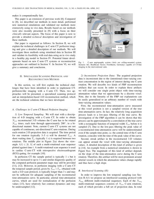
PUBLISHED IN: IEEE TRANSA<strong>CT</strong>IONS ON MEDICAL IMAGING, VOL. 31, NO. 4, PAGES 892–906, APRIL 2012 2makes it computationally fast.This paper is an extension of previous work [8]. Comparedto [8], we described our methods in more detail, performednew numerical simulations and validated our methods moreextensively using in vivo data. Results based on our methodswere also recently presented in [9] with a focus on theirclinically relevant aspects. The focus of this paper is now toprovide a detailed technical description and investigation ofthese methods.Our paper is organized as follows: In Section II, we willexplain the technical challenges in C-arm <strong>CT</strong> perfusion imagingand give a detailed description of our methods. We willinvestigate these methods using simulated data in Section IIIand validate its feasibility with real data using an in vivo studyin a healthy pig model in Section IV. Potential future developmentsbased on new C-arm <strong>CT</strong> systems or reconstructionapproaches are outlined in Section V. In Section VI, we willgive a summary and conclusion.Fig. 1. C-arm angiography system (Artis zee ceiling-mounted system,Siemens AG, Healthcare Sector, Forchheim, Germany) capable of <strong>CT</strong>-likeimaging in the interventional suite.II. SPECIALIZED SCANNING PROTOCOL ANDRECONSTRU<strong>CT</strong>ION METHODIn this section, we will first explain the technical challengesthat have been identified in order to implement <strong>CT</strong>perfusion-likeimaging with a C-arm <strong>CT</strong>. Then, two approacheswill be presented, a specialized scanning protocoland an interpolation-based 4-D reconstruction method, whichare the technical solutions that we have developed.A. Challenges in C-arm-<strong>CT</strong>-Based <strong>Perfusion</strong> <strong>Imaging</strong>1) Low Temporal Sampling: We will start with a descriptionof 4-D imaging with a C-arm <strong>CT</strong>. In order to obtainN rot reconstructed 3-D volumes the C-arm has to be rotatedN rot times, each time through approximately 200 ◦ , in a bidirectionalmanner. Note, current C-arm <strong>CT</strong> systems are notcapable of continuous, uni-directional C-arm rotations. Duringeach rotation 2-D projection data is acquired. The time periodfor one rotation (typically 3–5 s) will be denoted T rot . Ashort waiting time T w (typically 1 s) is required between tworotations. The middle plot in Figure 2(a) shows the viewangleλ(t) ∈ [0, Λ] of such a multi-rotational scan sequenceplotted against time t. A multi-rotational scan sequence is usedin cardiac C-arm <strong>CT</strong> with retrospective electrocardiogram(ECG)-gating, for example [10].In perfusion <strong>CT</strong> the sample period is typically 1 s but itmay be increased to up to 3 s and similar diagnostic quality ofthe computed perfusion parameter maps may still be provided[11], [12]. However, in perfusion imaging with a C-arm <strong>CT</strong>the temporal sample period, given by T rot +T w , obtained withsuch a 4-D scan protocol, is typically longer than 3 s and maynot be sufficient for adequate sampling of the reconstructedtime-attenuation curve. In particular, arterial time-attenuationcurves, which are used for normalization of the perfusionvalues [13], have relatively fast contrast dynamics and maybe undersampled [12].2) Inconsistent Projection Data: The acquired projectiondata is inconsistent due to the (intentional) time-varying contrastconcentration in the region of interest during one C-armrotation. We will describe two kinds of FBP reconstructionartifacts that can occur. In order to explain these artifactswe will consider one single point object with time-varyingattenuation values that we approximate by a discrete voxel.Note, due to the linearity of the FBP our explanations canbe easily generalized to an arbitrary number of voxels withtime-varying attenuation values.First, the reconstructed time-attenuation curve measuredat this voxel position is not a sampled version of the truetime-attenuation curve. In fact, the relatively long acquisitionprocess leads to a low-pass filtering of the true curve. Byinvestigation of the FBP algorithm it can be shown that thisprocess can be approximated by a convolution of the true curvewith a rectangular function of temporal width T rot before it issampled [7]. Due to the low-pass filtering the peak value ofa reconstructed time-attenuation curve will be underestimatedeven if the sample time point, i.e. the central time of the C-armrotation, coincides with the time of the peak value of the curve.Second, streak artifact in the reconstructed 3-D volumescan appear around the voxel with time-varying attenuationvalues. A detailed description of this kind of artifact is givenin [14]. An example from a numerical simulation is shown inFigure 8(a). The magnitude of this kind of artifact dependson the slope of the time-attenuation curve during the C-armrotation. Therefore, this artifact will be most prominent aroundarterial vessels in which the attenuation values change rapidlyand thus have a high slope.B. <strong>Interleaved</strong> Scanning (IS)In order to improve the low temporal sampling (see SectionII-A1) we propose an interleaved scanning protocol withN seq different multi-rotational sequences. Each of the N seqmulti-rotational sequences consists of N rot C-arm rotations,each of which provides a full set of projection data. In total