Assignment 5: Geometric Design Standards
Assignment 5: Geometric Design Standards
Assignment 5: Geometric Design Standards
- No tags were found...

You also want an ePaper? Increase the reach of your titles
YUMPU automatically turns print PDFs into web optimized ePapers that Google loves.
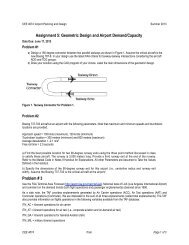
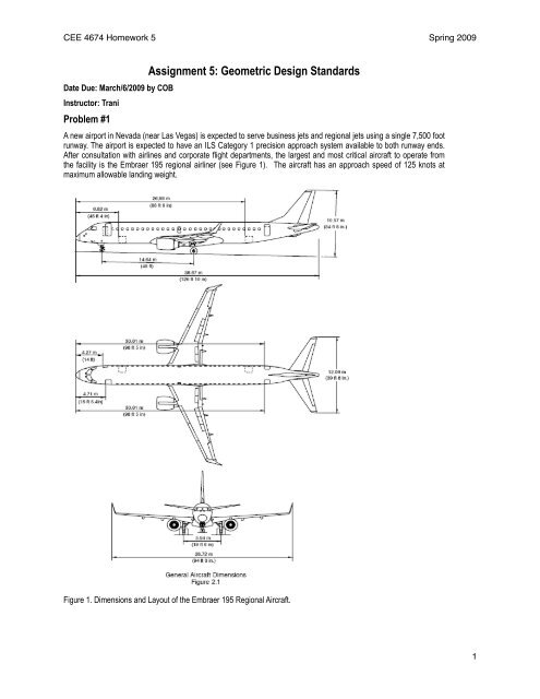
CEE 4674 Homework 5 Spring 2009Date Due: March/6/2009 by COBInstructor: TraniProblem #1<strong>Assignment</strong> 5: <strong>Geometric</strong> <strong>Design</strong> <strong>Standards</strong>A new airport in Nevada (near Las Vegas) is expected to serve business jets and regional jets using a single 7,500 footrunway. The airport is expected to have an ILS Category 1 precision approach system available to both runway ends.After consultation with airlines and corporate flight departments, the largest and most critical aircraft to operate fromthe facility is the Embraer 195 regional airliner (see Figure 1). The aircraft has an approach speed of 125 knots atmaximum allowable landing weight.Figure 1. Dimensions and Layout of the Embraer 195 Regional Aircraft. 1
CEE 4674 Homework 5 Spring 2009a) Determine the dimensions of the complete runway taxiway layout shown in Figure 2 (for the new airport). Clearlyindicate the FAA standards used.Figure 2. Simplified Airport Layout for Problem 1.The critical aircraft is the Embrer 195. The wingspan of the aircraft makes the aircraft ADG III. See Table below.Use ADG-III as critical aircraft and approach categories C and D.Dimension Length - feet (meters) RemarksB 100 (30) Runway width (Table 3-3)C 500 (150) Runway safety area width (Table 3-3)D 400 (122) Runway to taxiway centerline distance (Table 2-2)E 118 (36) Taxiway safety area width (Table 4-1)G 500 (150) Runway to aircraft parking area (Table 2-2)J 152 (46.5) Taxiway to parallel taxiway/taxilane distance (Table 2-3) 2
CEE 4674 Homework 5 Spring 2009Dimension Length - feet (meters) RemarksK 93 (28.5) Taxiway to fixed/movable object (Table 2-3)P 1000 (300) RSA length beyond runway end (Table 3-3)Q 800 (244) ROFA width (Table 3-3)R 1000 (300) ROFA beyond runway end (Table 3-3)W 50 (15) Taxiway width (Note that landing gear wheelbase is less than60 feet) (Table 4-1)Z 81 (24.5) Taxilane to fixed/movable object (Table 2-3)b)Find the size of the runway and taxiway shoulders needed at this airport.The runway shoulders need to be 20 feet (6 meters) (Table 3-3). The taxiway width will be 20 feet (6 meters) (Table4-1).c)Assuming the top of Figure 2 is the North side of the airport, find the closest distance from the runway that adeveloper could build a 4-story hotel (say 50 feet tall). Explain the controlling surfaces and dimensions considered inyour analysis.Surfaces to be tested: 1) Transitional surface extending at a slope 7:1 outwards from the primary surface and 2) therunwayTransitional surface drawingFigure 3. Transitional Surface Schematic.From figure 3 it is clear that the hotel is restricted to a minimum of 850 feet from the runway centerline. This will be incompliance of the Part 77 transitional surface.Runway OFZ surface schematic.Figure 4. Runway OFZ Surface Schematic.According to FAA design standards, “for CAT I runways, the inner transitional OFZ begins at the edges of the runway OFZ andinner-approach OFZ, then rises vertically for a height "H", and then slopes 6 (horizontal) to 1 (vertical) out to a height of 150 feet(45 m) above the established airport elevation.”The dimension of H is given by, 3
CEE 4674 Homework 5 Spring 2009Hfeet = 61 - 0.094(Sfeet) - 0.003(Efeet)where S is equal to the most demanding wingspan of the airplanes using the runway and E is equal to the runway thresholdelevation above sea level. Using the airport elevation at Las vegas (LAS), for the Embraer 195 aircraft the dimension H is: H = 61- 0.094 (94.25) - 0.003 (2181) or 45.6 feet.Figure 5. Solution for OFZ Inner Transitional Surface.The solution depicted in Figure 5 illustrates the inner transitional surface.The dominant effect for the BRL is the Part 77 transitional surface. The Building is restricted to 850 feet from therunway centerline (see Figure 3).d)Research on the internet the differences between Categories 1, 2 and 3 of the instrument landing system (ILS). Findthe visibility minima allowed for landings under each type of ILS system.CategoryRunway Visual Range(feet)Decision Height (feet)Category I 2000 200Category II < 2000 and >= 1000 100Category IIIa < 1000 and >= 700 0Category IIIb < 700 and >=150 0Category IIIc < 150 and >= 0 0Problem #2a)For problem described on page 37 of the revised geometric design handout (Notes 9), design a transition curve for point B(see Figure 6). Specify the elevations (every 10 meters) as a function of the station (in meters). Refer to the formulas on page41 of the handout to create a symmetrical parabola. Do it in Excel or Matlab to simplify your work.The change in grade is 1.4% (from 1.1% to -0.3%) therefore the length of the transition curve us 1,400 feet (427 meters). Thepoint of intersection is located at station 1806 metric. Since the parabola is symmetrical the starting point of the transition curve islocated at station 5223.4 feet ((1806 - 427/2)*3.28) or metric station 1592.5.The elevation of Point B can be easily calculated to be 625.951 meters above mean sea level. The elevation of the starting pointof the transition curve is 625.951 - (427/2) * (1.1/100) = 623.6025 meters. Using the Matlab code provided in class the followingtransition curve is obtained (Figure 7). 4
CEE 4674 Homework 5 Spring 2009Figure 6. Runway longitudinal Grades for Problem 2.Figure 7. Transition Curve for Point B.b)Find the maximum permissible longitudinal grade for the first 200 feet of the runway safety area of the runwayshown in Figure 6.According to the FAA AC 150/5300-13 the maximum grade for the 200 foot runway safety area is -3%.Figure 8. FAA Maximum Permissible Runway Longitudinal Grades. 5
CEE 4674 Homework 5 Spring 2009c) If the runway shown in Figure 3 serves aircraft in approach speed categories A and B would it meet all the currentlongitudinal grade FAA standards. Explain.Figure 9. Runway Longitudinal Grades for Approach Categories A and B.The maximum longitudinal grades are below 2% (OK).The maximum grade change is below 2% (OK).The distance between points of intersection is 2742 feet. This easily meets the required minima (486 feet).The runway would comply with all requirements of approach categories A and B.Problem #3The new airport in Florida with a 9000 foot runway needs runway exits. The airport authority wants at least three 90 degreeexits for the runway to serve distinct aircraft groups shown in Table 1. These three exits are in addition to the 90 degree angleexits at the end points of the runway.Table 1. Aircraft Parameters for Problem 4. Refer to Matlab Code in Notes 9 Handout for Explanations. All other Parameters areAssumed to Take Values Defined in the Handout.Aircraft Group Parameters Representative Aircraft(REDIM Name)Small single-engine GA aircraftBusiness jetsMedium-size transport aircraftApproach speed = 110 knotsTouchdown location = 275 metersAverage deceleration = -1.3 m/s-sFree roll time = 2.5 secondsApproach speed = 125 knotsTouchdown location = 350 metersAverage deceleration = -1.4 m/s-sFree roll time = 2.0 secondsApproach speed = 140 knotsTouchdown location = 420 metersAverage deceleration = -1.4 m/s-sFree roll time = 2.0 secondsCessna 208 (CE-208), Beech F33 (BE-F33A)Cessna 550 (CE-550), Learjet 31(Learjet 31),Boeing 737-400 (B-737-400), AirbusA320 (A-320-200)a) Find three runway exit locations (one for each aircraft group) using the three point method. Consider that therunway is used from both directions. 6
CEE 4674 Homework 5 Spring 2009Aircraft Group Parameters ResultsSmall single-engine GAaircraftBusiness jetsMedium-size transportaircraftApproach speed = 110 knotsTouchdown location = 275metersAverage deceleration = -1.3 m/s-sFree roll time = 2.5 secondsApproach speed = 125 knotsTouchdown location = 350meters Average deceleration =-1.4 m/s-sFree roll time = 2.0 secondsApproach speed = 140 knotsTouchdown location = 420meters Average deceleration =-1.4 m/s-sFree roll time = 2.0 secondsFlare distance = 275 metersTransition distance = 135.6 metersBraking distance = 980.6 metersTotal Distance to Runway Exit = 1391.2metersFlare distance = 350 metersTransition distance = 123.0 metersBraking distance = 1188.5 metersTotal Distance to Runway Exit = 1661.5metersFlare distance = 420 metersTransition distance = 137.7 metersBraking distance = 1510.5 metersTotal Distance to Runway Exit = 2068.2metersThe solution to the problem assumes a typical exit speed of 8 knots. This is consistent with observed values for rightanglerunway exits. Since the runway is 9000 feet long (2744 meters), we can sketch the following diagrams. Figure 11shows the recommended solution to the problem using the runway from both directions. Note that a single runway exitis located at the midpoint (1372 meters) to service small aircraft. This location is 20 meters from the optimal locationand seems a reasonable tradeoff to avoid two runway exits 40 meters apart. Figure 12 illustrates a solution with 3runway exits.Figure 10. One Direction Runway Exit Locations. Locations in Meters from Runway Threshold.Figure 11. Bi-Directional Runway Exit Locations. Locations in Meters from Each Runway Threshold. Five Runway ExitsPlus two Runway End Exits. 7
CEE 4674 Homework 5 Spring 2009Figure 12. Bi-Directional Runway Exit Locations. Locations in Meters from Each Runway Threshold. Three RunwayExits Plus two Runway End Exits.b) Specify the radius of the centerline curve to be used in the construction of the three runway exits. Since the airport isused by multiple aircraft groups use the critical aircraft as the basis for your selection.The radius of a 90-degree runway exit is 250 feet. 8