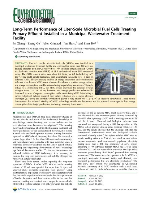
Long-Term Performance of Liter-Scale Microbial Fuel Cells Treating ...
Long-Term Performance of Liter-Scale Microbial Fuel Cells Treating ...
Long-Term Performance of Liter-Scale Microbial Fuel Cells Treating ...

You also want an ePaper? Increase the reach of your titles
YUMPU automatically turns print PDFs into web optimized ePapers that Google loves.
Environmental Science & TechnologyArticleFigure 2. Concentrations <strong>of</strong> suspended solids in the primary effluentsand the MFC anode effluents: (A) TSS and (B) VSS.Figure 1. Organic concentrations in the primary effluent and the MFCanode effluents: (A) TCOD, (B) SCOD, and (C) organicconcentrations in the catholyte.effluent from anaerobic treatment (MFC anode) can be furtherimproved through aerobic polishing. 19 This post-aerobictreatment was also important to the pH <strong>of</strong> the solution,because we observed that the anolyte pH varied between 4.0and 6.5 and the pH <strong>of</strong> the catholyte was about 7.5−8.5 (seeFigure S3 <strong>of</strong> the Supporting Information).Suspended solids (SS) in biological treatment are related tothe production <strong>of</strong> secondary sludge. In this study, wemonitored the concentrations <strong>of</strong> both TSS and VSS (Figure2) and found that the anodes <strong>of</strong> the MFCs reduced about 50%TSS and VSS. In the tank that collected the catholyte (whichpossibly acted as a sedimentation tank), the SS concentrationsbecame even lower at 14 ± 18 mg <strong>of</strong> TSS/L and 4 ± 10 mg <strong>of</strong>VSS/L (see Table S1 <strong>of</strong> the Supporting Information). Similarly,the MFC anodes decreased turbidity, another indicator <strong>of</strong> theparticle concentration in water, which was also further reducedin the catholyte (see Figure S4 <strong>of</strong> the Supporting Information).For comparison, the SS concentrations in the aeration tanks <strong>of</strong>the South Shore Water Reclamation Facility were 2214 ± 314mg <strong>of</strong> TSS/L and 1642 ± 242 mg <strong>of</strong> VSS/L. Although the postaerobicpolishing would accumulate sludge via aerobic activities(unfortunately, we did not quantify biosolid accumulation inthe tank collecting the catholyte), in general, the MFC + postaerobictreatment is expected to produce much less sludge thanan activated sludge process, because <strong>of</strong> significant reduction <strong>of</strong>organic compounds in the MFC anodes (65−70%, while thecathode removed another 20−25%). The low biomass yield inthe MFCs was also observed in the prior studies <strong>of</strong> laboratorysystems. 20,21 As a result, the use <strong>of</strong> a secondary clarifier will begreatly reduced, thereby saving a tremendous amount <strong>of</strong> energyand effort for sludge disposal.As expected, the anodes <strong>of</strong> the MFCs did not achieve anyobvious removal <strong>of</strong> nitrogen and phosphorus. The concentrations<strong>of</strong> ammonium, nitrite, and nitrate are shown in FiguresS5−S7 <strong>of</strong> the Supporting Information, respectively, and thephosphate concentration is shown in Figure S8 <strong>of</strong> theSupporting Information. However, the catholyte showed asignificantly lower concentration <strong>of</strong> ammonium (see Figure S5<strong>of</strong> the Supporting Information) and accumulation <strong>of</strong> nitrate(see Figure S7 <strong>of</strong> the Supporting Information), indicating thepresence <strong>of</strong> nitrification. We have investigated nitrogen removalin greater detail by linking a denitrifying MFC to the MFC-AC,which is introduced in the following section. The MFC anodesdid not achieve any significant removal <strong>of</strong> coliform bacteria,which were mainly affected by season and temperature (seeFigure S9 <strong>of</strong> the Supporting Information).Electricity Generation. Electric current was used as aparameter to monitor the long-term performance <strong>of</strong> electricitygeneration in the MFCs; power and energy were also analyzed.Both MFCs exhibited high current generation in the first 180days (Figure 3), likely because <strong>of</strong> high organic concentrations inthe primary effluent during that period (panels A and B <strong>of</strong>Figure 1). For most <strong>of</strong> the time, two tubes <strong>of</strong> a MFC (seeFigure S1 <strong>of</strong> the Supporting Information) were connected byone electric circuit, in which two anode carbon brushes wereconnected together as one anode and two cathodes were linkedas one cathode. Between days 57 and 104, we separated thecircuit into two to examine whether power and energyproduction could be higher; that is, each tube functioned asan independent MFC. The results did not support our idea;therefore, the two individual circuits were combined back toone after day 104. The large variation in current generation waspossibly because <strong>of</strong> the varied organic concentrations andconductivity in the primary effluent; the sharp decreasing lines,especially those that decreased to a level close to zero in a short4943dx.doi.org/10.1021/es400631r | Environ. Sci. Technol. 2013, 47, 4941−4948
Environmental Science & TechnologyArticleFigure 3. Pr<strong>of</strong>iles <strong>of</strong> current generation during the operating period:(A) MFC-AC and (B) MFC-Pt.period <strong>of</strong> time, were mostly because the tubing cloggingstopped the supply <strong>of</strong> the primary effluent (or the anodeemptiness test). We expect that the tube clogging can beovercome in a larger scale MFC system, which will have a muchfaster feeding flow rate. The gradual decrease in the currentafter day 400 was due to the decreasing temperature (seeFigure S2 <strong>of</strong> the Supporting Information). Bi<strong>of</strong>ouling <strong>of</strong> bothmembrane and cathode electrode over time might alsocontribute to the decreasing current. In general, there wasnot an obvious difference in current generation between thetwo MFCs, both <strong>of</strong> which achieved similar CEs and CRs (seeTable S1 <strong>of</strong> the Supporting Information), suggesting thatactivated carbon (AC) powder can be an effective catalyst in aMFC. 22 However, we do not think that AC powder is goodenough to replace platinum in any other oxygen-reductionprocesses, such as conventional hydrogen fuel cells. Therelatively comparable performance that AC powder achieved ina MFC is likely due to the low demand <strong>of</strong> oxygen reduction;that is, platinum is “overqualified” to be a catalyst for MFCs.The low Pt loading rate on the cathode electrode might also beone <strong>of</strong> the reasons why the MFC-Pt did not outperform theMFC-AC. Nevertheless, the cathode catalyst is not the focus <strong>of</strong>this study, and our results show that AC powder could be analternative catalyst for further MFC development.Energy production is a key parameter to properly evaluatethe benefits <strong>of</strong> MFC technology for wastewater treatment. 14We analyzed energy production and consumption andestablished a preliminary energy balance (Table 1). Energyproduction was expressed as kilowatt hours per cubic meter <strong>of</strong>treated wastewater or kilogram <strong>of</strong> removed COD (eitherTCOD or SCOD). Energy consumption included theconsumption by pumps for feeding and recirculation; thefeeding energy could be neglected in comparison to therecirculation energy. The two MFCs produced comparableelectric energy but had different energy consumption, mainlybecause <strong>of</strong> the difference in hydraulic head loss, which is a keyelement in estimating energy consumption (details in theSupporting Information). The measured hydraulic head loss <strong>of</strong>Table 1. Summary <strong>of</strong> Energy Production and Consumption in the MFCs aenergy production energy consumption energy balancekWh/m 3 kWh/kg <strong>of</strong> TCOD kWh/kg <strong>of</strong> SCOD kWh/m 3 kWh/kg <strong>of</strong> TCOD kWh/kg <strong>of</strong> SCOD kWh/m 3 kWh/kg <strong>of</strong> TCOD kWh/kg <strong>of</strong> SCODMFC-AC 0.0255 (0.0204) 0.0794 (0.1015) 0.1702 (0.2433) 0.0238 (0.0045) 0.0761 (0.0748) 0.1698 (0.1915) 0.0017 (0.0248) 0.0034 (0.1763) 0.0004 (0.4348)MFC-Pt 0.0239 (0.0186) 0.0739 (0.0653) 0.1643 (0.1792) 0.0147 (0.0004) 0.0547 (0.0473) 0.1462 (0.2206) 0.0092 (0.0190) 0.0192 (0.1127) 0.0181 (0.3998)N-MFC b 0.0078 (0.0059) 0.0236 (0.0195) 0.0391 (0.0287) 0.0238 (0.0045) 0.0769 (0.0293) 0.1746 (0.1442) −0.0160 (0.0104) −0.0532 (0.0488) −0.1356 (0.1729)a The values in parentheses are standard deviations.b The MFC system for nitrogen removal consisted <strong>of</strong> the MFC-AC and a denitrifying MFC.4944dx.doi.org/10.1021/es400631r | Environ. Sci. Technol. 2013, 47, 4941−4948
Environmental Science & Technologythe anode recirculation pump for the MFC-AC was 19.0 ± 6.1cm, significantly higher than 6.7 ± 0.6 cm with the MFC-Pt.We found that this difference was related to the size <strong>of</strong> tubingconnectors; we accidently used smaller size connectors in theMFC-AC, which resulted in a higher hydraulic head loss. Thisindicates that, in designing future MFC systems, the size <strong>of</strong>connector/port should be large enough to reduce hydraulichead loss and, thus, energy consumption. Overall, both MFCsachieved positive energy balances with large standard deviations(Table 1); the MFC-Pt had a more positive balance because <strong>of</strong>less energy consumption.For practical application, it is important to have durable andstable treatment technology, which is related to themaintenance and operating expense. A potential concern withusing the anode effluent as a catholyte is the overgrowth <strong>of</strong>bi<strong>of</strong>ilm on the cathode electrode stimulated by the remainingorganics/nitrogen in the anode effluent. During the operation,bi<strong>of</strong>ilm formed on the cathode electrode and possiblyfunctioned as post-treatment <strong>of</strong> organics and nitrogen;however, we did not clean the cathode electrode during theentire experimental period. This suggests that bi<strong>of</strong>ilm formationwas not as serious as expected and did not significantly affectelectricity generation. We also examined the response <strong>of</strong> theMFCs to fluctuation under two conditions. The first conditionwas to mimic a situation in which the anode compartmentswere emptied for repair or other maintenance; in this case,oxygen enters the anode compartment after the water wasemptied. The emptiness was held for 3, 2, and 1 day, and weobserved that the current generation in the two MFCsrecovered from oxygen intrusion in a few days, dependingupon the length <strong>of</strong> the exposure (Figure 4A). Thisdemonstrates that the MFCs could successfully handle oxygenflux for a short period <strong>of</strong> time, likely benefiting from facultativemicroorganisms in the anode community. The secondcondition was to simulate a larger water flux for a short periodin the case <strong>of</strong> rain or storm. The large water flux alters theanolyte HRT, and thus, we examined three HRTs: 12 h, 6 h,and 3 h. The amount <strong>of</strong> the wastewater at a HRT <strong>of</strong> 3 h was 4times greater that at 12 h, higher than common ratios <strong>of</strong> thetreatment capacities between dry and wet weather. TCODremoval decreased with the decreasing HRTs in both MFCs,because <strong>of</strong> a higher organic loading rate at a smaller HRT(Figure 4B). The current generation in the MFC-AC slightlydecreased, but the MFC-Pt had a more significant drop in itscurrent at shorter HRTs (the inset <strong>of</strong> Figure 4B), which mightbe attributed to Pt catalyst contamination by serious bi<strong>of</strong>oulingfrom more organic input, but the exact reason is not clear atthis moment. Both MFCs recovered to regular performanceafter the HRT was adjusted back to 12 h. We are moreoptimistic about the COD removal during shorter HRTs andexpect much higher removal efficiencies than those shown inFigure 4B, because rainwater will greatly dilute the COD andthe actual organic loading rate may not increase significantly.Nitrogen Removal. Nitrogen removal is <strong>of</strong> great interest inwastewater treatment because <strong>of</strong> the tightened regulations onnitrogen discharge. Ammonia cannot be effectively oxidizedunder the anaerobic condition <strong>of</strong> the anode <strong>of</strong> a MFC; 23however, it was found that nitrate can be bioelectrochemicallyreduced on the cathode by accepting electrons from a cathodeelectrode. 24 In the cathode <strong>of</strong> the present MFCs, nitrate wasproduced and accumulated and ammonium was reduced to avery low level (see Figures S5 and S7 <strong>of</strong> the SupportingInformation ), indicating the occurrence <strong>of</strong> nitrification. The4945ArticleFigure 4. MFC performance in response to fluctuation: (A) emptyingthe anode for different periods and (B) different HRTs (bars representTCOD removal and dots/lines represent current density).concentration <strong>of</strong> total nitrogen in the final effluent (from thecathode) was dominated by the nitrate concentration; therefore,to improve the removal <strong>of</strong> total nitrogen, we connected adenitrifying MFC for nitrate reduction to the MFC-AC on day301.Such a cooperative system between a denitrifying MFC and aregular MFC (as shown by the inset <strong>of</strong> Figure 5A) significantlyimproved the nitrogen removal. The concentration <strong>of</strong> nitratewas reduced from 21.4 ± 10.2 mg/L in the cathode effluent <strong>of</strong>the MFC-AC to 4.9 ± 3.8 mg/L in the cathode effluent <strong>of</strong> thedenitrifying MFC (also the final effluent <strong>of</strong> the MFCtreatment), about a 77% reduction (Figure 5B). The averagecurrent <strong>of</strong> the denitrifying MFC was about 8.6 mA, resulting ina CE <strong>of</strong> 14.3% based on nitrate removal, which was lower thanthose obtained in our previous studies. 25,26 The total nitrogen(sum <strong>of</strong> TKN, nitrate, and nitrite) was reduced by 76.2%, muchhigher than 27.1% without the denitrifying MFC. As expected,the ammonium or TKN concentrations were not obviouslyaffected by the denitrifying cathode (panels A and B <strong>of</strong> Figure5), and some loss <strong>of</strong> ammonium or TKN in the anodes <strong>of</strong> theMFCs was likely due to ammonium ion movement throughCEM 27 and microbial synthesis. The denitrifying MFC alsoremoved 31.8 ± 23.2% TCOD or 38.3 ± 15.3% SCOD.Excessive consumption <strong>of</strong> organic compounds in the anode <strong>of</strong>the denitrifying MFC was not desired, because it would reduceenergy production in the MFC-AC and result in a negativeenergy balance (Table 1); the denitrifying MFC was operatedunder a high-current mode, and thus, little electric power/energy was produced.Carbon Balance. A mass balance <strong>of</strong> carbon compoundsbased on either TCOD or SCOD was established with thedx.doi.org/10.1021/es400631r | Environ. Sci. Technol. 2013, 47, 4941−4948
Environmental Science & TechnologyFigure 5. Concentrations <strong>of</strong> nitrogen compounds in the MFCsdesigned for nitrogen removal: (A) TKN and (B) ammonium, nitrate,and nitrite. (Inset) Schematic <strong>of</strong> the MFC system consisting <strong>of</strong> adenitrifying MFC and the MFC-AC. PE, primary effluent; D-MFC-a,anode <strong>of</strong> the denitrifying MFC; MFC-a, anode <strong>of</strong> the MFC-AC; MFCc,cathode <strong>of</strong> the MFC-AC; and D-MFC-c, cathode <strong>of</strong> the denitrifyingMFC.MFC-Pt by analyzing the contributions from different sources,including electricity, methane, oxygen, sulfate, and otherunknown factors (Figure 6 and Table S2 <strong>of</strong> the SupportingFigure 6. Carbon balance based on TCOD obtained from the MFC-Pt.Information). Because carbon is an electron donor, this balancecould also represent an electron balance. Derived from CE, thecarbon distribution to electricity production was 13.2% (on thebasis <strong>of</strong> TCOD) or 22.8% (on the basis <strong>of</strong> SCOD).Surprisingly, sulfate consumed much more carbon thanelectricity production (37.2% TCOD or 64.0% SCOD). Theprimary effluent contained a sulfate concentration <strong>of</strong> 119.6 ±69.7 mg <strong>of</strong> SO 4 2‐ /L, and the anode removed 81.2 ± 17.2%sulfate, indicating an active sulfate reduction in the MFC anode.The primary effluent contained dissolved oxygen <strong>of</strong> 3.3 ± 1.3mg/L, which could consume 2.2% TCOD or 3.8% SCOD.4946ArticleOxygen flux through the CEM was estimated to contribute to11.7% TCOD or 20.2% SCOD. Methane production wasobserved in MFCs, 28 and thus, we examined both methane gasand the dissolved methane in the anode effluent. The averageconcentration <strong>of</strong> the dissolved methane was about 1 mg/L, andmethane gas production was ∼0.5 mL/g <strong>of</strong> SCOD, resulting incarbon consumption <strong>of</strong> 1.3% TCOD (or 2.2% SCOD) and0.04% TCOD (or 0.1% SCOD), respectively.There was 34.4% TCOD unaccounted for by thesecalculations, while there was 13.1% SCOD overly accounted(see Table S2 <strong>of</strong> the Supporting Information). The possiblemeasurement/analytic errors (e.g., collection <strong>of</strong> methane gas)might also lead to unknown carbon flow in the TCODcalculation. For the balance <strong>of</strong> SCOD, the total input coulombscould have been underestimated, because additional SCODcould be produced from the degradation <strong>of</strong> TCOD. Becausesulfate reduction was found to be a major contributor to CODremoval, it would be interesting to know whether inhibitingsulfate reduction could improve electricity production. We haveconducted the tests on inhibiting sulfate reduction, which canbe found in the Supporting Information. Because <strong>of</strong> thesignificant variation <strong>of</strong> wastewater quality and testing conditionsin the field that could strongly disturb the experimental results,we cannot draw any definitive conclusions on the effect <strong>of</strong>sulfate reduction on electricity generation, and more laboratorytests under controlled conditions will be needed to further ourunderstanding <strong>of</strong> this issue.Perspectives. A proper understanding <strong>of</strong> the applicationniche and the benefits <strong>of</strong> the MFC technology is very importantto its development. It is critical to acknowledge that the primaryfunction <strong>of</strong> MFCs is wastewater treatment instead <strong>of</strong> energyproduction (which is an added benefit). MFCs are advantageousin several aspects. (1) Low energy consumption: A MFCsystem avoids the use <strong>of</strong> aeration, which consumes about 50%<strong>of</strong> the electric energy <strong>of</strong> an aerobic wastewater treatmentprocess. (2) Low sludge production: the anaerobic process inthe anodes <strong>of</strong> a MFC system accumulates little secondarysludge. This result has two potential benefits: minimizing theuse <strong>of</strong> a secondary clarifier to save both operation andinfrastructure expense and reducing the treatment <strong>of</strong> secondarysludge, which requires significant effort and energy. (3) Energyrecovery from wastewater: the electric energy produced by aMFC system could be used to <strong>of</strong>fset the energy requirement bythe pumping system, thereby further reducing the energyconsumption <strong>of</strong> the wastewater treatment process.We have not observed satisfactory energy production fromhigh-strength/high-solid wastes in MFCs; 29 therefore, webelieve that MFCs cannot compete with anaerobic digestionfor the treatment <strong>of</strong> high-strength/high-solid wastes, 30 andMFCs are more suitable for medium- and low-strengthwastewater that is currently treated by aerobic processes.However, with the increased attention to anaerobic treatment[e.g., anaerobic membrane bioreactor (AnMBR)] <strong>of</strong> domesticwastewater, 31,32 there will be competition between conventionalanaerobic treatment and MFC technologies (if provenapplicable in the future). In comparison to conventionalanaerobic treatment <strong>of</strong> low-strength wastewater, the potentialadvantages <strong>of</strong> MFC technology may exist in several aspects: (1)better ability to handle temperature variation, especially at lowtemperatures, (2) no need <strong>of</strong> gas collection, treatment, andconverting system (for energy production) because <strong>of</strong> directelectricity production, (3) low dissolved methane in the treatedeffluent to avoid the release <strong>of</strong> greenhouse gas, and (4) nitrogendx.doi.org/10.1021/es400631r | Environ. Sci. Technol. 2013, 47, 4941−4948
Environmental Science & TechnologyArticleremoval with linking to specially designed MFC systems.Integrating membrane technology into MFCs can also producehigh-quality effluent, 33 such as that in AnMBRs. Thoseadvantages need to be further verified and demonstrated withmore work <strong>of</strong> larger scale MFCs treating actual wastewater.Although energy production may not be the most importantfeature <strong>of</strong> MFC technology, it is still beneficial to furtherimprove electricity production by optimizing MFC configuration,materials, and operation. For instance, we recently usedspiral spacers to double energy production in tubular MFCs. 34Nitrogen removal is certainly possible in the present MFCsystem, and carbon distribution should be carefully coordinatedfor■the purpose <strong>of</strong> energy production.ASSOCIATED CONTENT*S Supporting InformationCalculation <strong>of</strong> CE, energy consumption, and oxygen flux,details <strong>of</strong> the sulfate-reduction inhibition test, summary <strong>of</strong> thetreatment performance in Table S1, data <strong>of</strong> carbon balance inTable S2, and MFC schematic and data <strong>of</strong> the temperature,nutrients, coliform bacteria, and sulfate in Figures S1−S10. Thismaterial is available free <strong>of</strong> charge via the Internet at http://pubs.acs.org.■ AUTHOR INFORMATIONCorresponding Author*Telephone: (414) 229-5846. Fax: (414) 229-6958. E-mail:zhenhe@uwm.edu.NotesThe authors declare no competing financial interest.■ ACKNOWLEDGMENTSThis study was financially supported by a grant from VeoliaWater North America. The authors thank MilwaukeeMetropolitan Sewerage District (MMSD) for providing atesting site at the South Shore Water Reclamation Facility. Theauthors also thank Yann Moreau, Caroline Dale, KhristopherRadke, Scott Royer, Mark Swayne, and Ronan Treguer fromVeolia Water, Christopher Magruder from MMSD, and KyleJacobson from University <strong>of</strong> WisconsinMilwaukee for theirhelp with the project, Michelle Schoenecker from University <strong>of</strong>WisconsinMilwaukee for pro<strong>of</strong>reading the manuscript, andanonymous reviewers for their helpful comments.■ REFERENCES(1) Logan, B. Essential data and techniques for conducting microbialfuel cell and other types <strong>of</strong> bioelectrochemical system experiments.ChemSusChem 2012, 5 (6), 988−994.(2) Logan, B.; Rabaey, K. Conversion <strong>of</strong> wastes into bioelectricityand chemicals using microbial electrochemical technologies. Science2012, 337, 686−690.(3) Moon, H.; Chang, I. S.; Kim, B. H. Continuous electricitygeneration from artificial wastewater using a mediator-less microbialfuel cell. Bioresour. Technol. 2006, 97, 621−627.(4) Borole, A. P.; Aaron, D.; Hamilton, C. Y.; Tsouris, C.Understanding long-term changes in microbial fuel cell performanceusing electrochemical impedance spectroscopy. Environ. Sci. Technol.2010, 44 (7), 2740−2745.(5) Zhang, F.; Pant, D.; Logan, B. E. <strong>Long</strong>-term performance <strong>of</strong>activated carbon air cathodes with different diffusion layer porosities inmicrobial fuel cells. Biosens. Bioelectron. 2011, 30 (1), 49−55.(6) Zhang, G.; Wang, K.; Zhao, Q.; Jiao, Y.; Lee, D.-J. Effect <strong>of</strong>cathode types on long-term performance and anode bacterial4947communities in microbial fuel cells. Bioresour. Technol. 2012, 118,249−256.(7) Li, X.; Zhu, N.; Wang, Y.; Li, P.; Wu, P.; Wu, J. Animal carcasswastewater treatment and bioelectricity generation in up-flow tubularmicrobial fuel cells: Effects <strong>of</strong> HRT and non-precious metallic catalyst.Bioresour. Technol. 2012, 128, 454−460.(8) Zhuang, L.; Yuan, Y.; Wang, Y.; Zhou, S. <strong>Long</strong>-term evaluation <strong>of</strong>a 10-liter serpentine-type microbial fuel cell stack treating brewerywastewater. Bioresour. Technol. 2012, 123, 406−412.(9) Jiang, D.; Curtis, M.; Troop, E.; Scheible, K.; McGrath, J.; Hu, B.;Suib, S.; Raymond, D.; Li, B. A pilot-scale study on utilizing multianode/cathodemicrobial fuel cells (MAC MFCs) to enhance thepower production in wastewater treatment. Int. J. Hydrogen Energy2011, 36 (1), 876−884.(10) Logan, B. E. Scaling up microbial fuel cells and otherbioelectrochemical systems. Appl. Microbiol. Biotechnol. 2010, 85 (6),1665−1671.(11) Logan, B. E.; Call, D.; Cheng, S.; Hamelers, H. V.; Sleutels, T.H.; Jeremiasse, A. W.; Rozendal, R. A. <strong>Microbial</strong> electrolysis cells forhigh yield hydrogen gas production from organic matter. Environ. Sci.Technol. 2008, 42 (23), 8630−8640.(12) Cusick, R. D.; Bryan, B.; Parker, D. S.; Merrill, M. D.; Mehanna,M.; Kiely, P. D.; Liu, G.; Logan, B. E. <strong>Performance</strong> <strong>of</strong> a pilot-scalecontinuous flow microbial electrolysis cell fed winery wastewater. Appl.Microbiol. Biotechnol. 2011, 89 (6), 2053−2063.(13) Heidrich, E. S.; Dolfing, J.; Scott, K.; Edwards, S. R.; Jones, C.;Curtis, T. P. Production <strong>of</strong> hydrogen from domestic wastewater in apilot-scale microbial electrolysis cell. Appl. Microbiol. Biotechnol. 2012.(14) He, Z. <strong>Microbial</strong> fuel cells: Now let us talk about energy.Environ. Sci. Technol. 2013, 47, 332−333.(15) Zhang, F.; Jacobson, K. S.; Torres, P.; He, Z. Effects <strong>of</strong> anolyterecirculation rates and catholytes on electricity generation in a literscaleupflow microbial fuel cell. Energy Environ. Sci. 2010, 3, 1347−1352.(16) Clauwaert, P.; Mulenga, S.; Aelterman, P.; Verstraete, W. Litrescalemicrobial fuel cells operated in a complete loop. Appl. Microbiol.Biotechnol. 2009, 83 (2), 241−247.(17) Clesceri, L. S.; Greenberg, A. E.; Eaton, A. D. Standard Methodsfor the Examination <strong>of</strong> Water and Wastewater, 20th ed.; AmericanPublic Health Association: Washington, D.C., 1998.(18) Souza, C. L.; Chernicharo, C. A.; Aquino, S. F. Quantification <strong>of</strong>dissolved methane in UASB reactors treating domestic wastewaterunder different operating conditions. Water Sci. Technol. 2011, 64(11), 2259−2264.(19) Haandel, A.; Kato, M.; Cavalcanti, P.; Florencio, L. Anaerobicreactor design concepts for the treatment <strong>of</strong> domestic wastewater. Rev.Environ. Sci. Bio/Technol. 2006, 5, 21−38.(20) Rabaey, K.; Lissens, G.; Siciliano, S. D.; Verstraete, W. Amicrobial fuel cell capable <strong>of</strong> converting glucose to electricity at highrate and efficiency. Biotechnol. Lett. 2003, 25 (18), 1531−1535.(21) Freguia, S.; Rabaey, K.; Yuan, Z.; Keller, J. Electron and carbonbalances in microbial fuel cells reveal temporary bacterial storagebehavior during electricity generation. Environ. Sci. Technol. 2007, 41(8), 2915−2921.(22) Dong, H.; Yu, H.; Wang, X. Catalysis kinetics and porousanalysis <strong>of</strong> rolling activated carbon-PTFE air-cathode in microbial fuelcells. Environ. Sci. Technol. 2012, 46 (23), 13009−13015.(23) He, Z.; Kan, J. J.; Wang, Y. B.; Huang, Y. L.; Mansfeld, F.;Nealson, K. H. Electricity production coupled to ammonium in amicrobial fuel cell. Environ. Sci. Technol. 2009, 43 (9), 3391−3397.(24) Clauwaert, P.; Rabaey, K.; Aelterman, P.; Schamphelaire, L. D.;Pham, T. H.; Boeckx, P.; Boon, N.; Verstraete, W. Biologicaldenitrification in microbial fuel cells. Environ. Sci. Technol. 2007, 41(9), 3354−3360.(25) Zhang, F.; He, Z. Simultaneous nitrification and denitrificationwith electricity generation in dual-cathode microbial fuel cells. J. Chem.Technol. Biotechnol. 2012, 87, 153−159.dx.doi.org/10.1021/es400631r | Environ. Sci. Technol. 2013, 47, 4941−4948
Environmental Science & TechnologyArticle(26) Zhang, F.; He, Z. Integrated organic and nitrogen removal withelectricity generation in a tubular dual-cathode microbial fuel cell.Process Biochemistry 2012, 47, 2146−2151.(27) Cord-Ruwisch, R.; Law, Y.; Cheng, K. Y. Ammonium as asustainable proton shuttle in bioelectrochemical systems. Bioresour.Technol. 2011, 102 (20), 9691−9696.(28) He, Z.; Minteer, S. D.; Angenent, L. T. Electricity generationfrom artificial wastewater using an upflow microbial fuel cell. Environ.Sci. Technol. 2005, 39 (14), 5262−5267.(29) Ge, Z.; Zhang, F.; Grimaud, J.; Hurst, J.; He, Z. <strong>Long</strong>-terminvestigation <strong>of</strong> microbial fuel cells treating primary sludge or digestedsludge. Bioresour. Technol. 2013, DOI: 10.1016/j.biortech.2013.03.016.(30) Pham, T. H.; Rabaey, K.; Aelterman, P.; Clauwaert, P.; DeSchamphelaire, L.; Boon, N.; Verstraete, W. <strong>Microbial</strong> fuel cells inrelation to conventional anaerobic digestion technology. Eng. Life Sci.2006, 6 (3), 285−292.(31) McCarty, P. L.; Bae, J.; Kim, J. Domestic wastewater treatmentas a net energy producer−Can this be achieved? Environ. Sci. Technol.2011, 45 (17), 7100−7106.(32) Smith, A. L.; Stadler, L. B.; Love, N. G.; Skerlos, S. J.; Raskin, L.Perspectives <strong>of</strong> anaerobic membrane bioreactor treatment <strong>of</strong> domesticwastewater: A cricial review. Bioresour. Technol. 2012, 122, 149−159.(33) Ge, Z.; Ping, Q.; He, Z. Hollow-fiber membrane bioelectrochemicalreactor for domestic wastewater treatment. J. Chem.Technol. Biotechnol. 2013, DOI: 10.1002/jctb.4009.(34) Zhang, F.; Ge, Z.; Grimaud, J.; Hurst, J.; He, Z. Improvingelectricity production in tubular microbial fuel cells through optimizingthe anolyte flow with spiral spacers. Bioresour. Technol. 2013, 134,251−256.4948dx.doi.org/10.1021/es400631r | Environ. Sci. Technol. 2013, 47, 4941−4948