Electrical conduction and Joule effect in one-dimensional chains of ...
Electrical conduction and Joule effect in one-dimensional chains of ...
Electrical conduction and Joule effect in one-dimensional chains of ...

You also want an ePaper? Increase the reach of your titles
YUMPU automatically turns print PDFs into web optimized ePapers that Google loves.
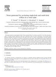
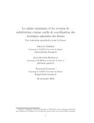
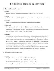
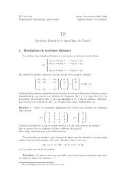
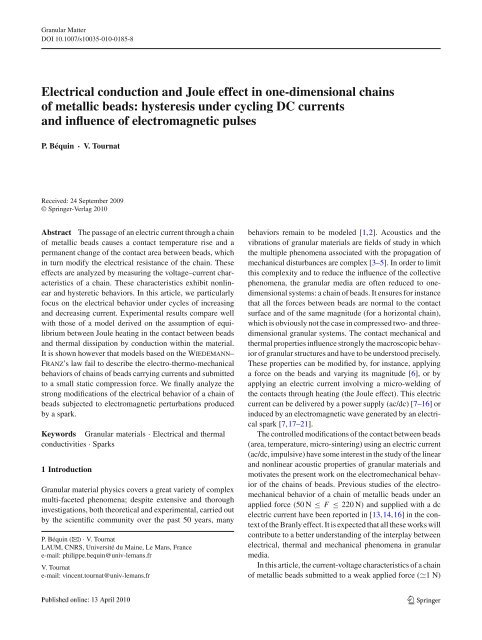
<strong>Electrical</strong> <strong>conduction</strong> <strong>in</strong> cha<strong>in</strong>s <strong>of</strong> beadsFig. 6 Variation <strong>of</strong> voltage U as a function <strong>of</strong> current I . Cha<strong>in</strong> <strong>of</strong> 5sta<strong>in</strong>less beads (diameter 11 mm). Comparison between experimentaldata (×) <strong>and</strong> analytical model (−) with the adjusted parameters (Eq. 6).Decreas<strong>in</strong>g current: α ↓ =+1.1×10 −3 <strong>and</strong> β ↓ = −6.9×10 −4 ;<strong>in</strong>creas<strong>in</strong>gcurrent α ↑ =+2.1 × 10 −3 <strong>and</strong> β ↑ =+7.0 × 10 −4<strong>of</strong> beads has a slightly higher resistance to the flow <strong>of</strong> electriccharge R lc↑ ≃ 2.1 (part DE, Figs. 2 <strong>and</strong> 6) thanforthe weak decreas<strong>in</strong>g currents R lc↓ ≃ 2.0 (part CD, Fig. 6).This difference is ma<strong>in</strong>ly due to the thermal delays associatedto the relatively fast evolution <strong>of</strong> the electric current. Indeed,for a given small current <strong>in</strong> the decreas<strong>in</strong>g phase (part CD),the bulk <strong>of</strong> the beads presents a lower temperature <strong>and</strong> thus alower measured voltage compared to those <strong>of</strong> the <strong>in</strong>creas<strong>in</strong>gphase <strong>of</strong> current (part DE). Thus the cha<strong>in</strong> <strong>of</strong> beads has anelectromechanical behavior <strong>of</strong> hysteretic type for which thevoltage–current characteristics present a loop (Fig. 6). Thelarger is the loop, the greater is the thermal energy released<strong>in</strong> the cha<strong>in</strong> <strong>and</strong> consequently the more the beads warm up.These phenomena are more pronounced for cycles <strong>of</strong> higherelectric currents, as shown later <strong>in</strong> Fig. 7.4 Model<strong>in</strong>g <strong>of</strong> the hysteretic behavior CD-DEIn the follow<strong>in</strong>g, the measured hysteretic current–voltagecharacteristics (parts CD <strong>and</strong> DE) are compared with thoseresult<strong>in</strong>g from an analytical model [7,8,12–14,24].The two beads <strong>in</strong> contact are considered as two homogeneous<strong>and</strong> isotropic metal conductors with large dimensionscompared to the contact radius. The electric currentgoes <strong>in</strong>to <strong>and</strong> leaves by surface ends S 1 <strong>and</strong> S 2 (Fig. 3).The heat flux only runs out through these same surfaces.For side surfaces, the losses by <strong>conduction</strong>, convection orradiation are neglected. It should be noted that the thermalconductivities <strong>of</strong> the air (λ air ≃ 0.026 W m −1 K −1 )<strong>and</strong>thePVC tubes (λ PVC ≃ 0.16 W m −1 K −1 )aremuchsmallerthan thermal conductivity with<strong>in</strong> the sta<strong>in</strong>less steel (λ steel ≃15 W m −1 K −1 ).Equipotential surfaces <strong>in</strong> the whole bead are also isothermalsurfaces. The two networks <strong>of</strong> equipotential <strong>and</strong>Fig. 7 Voltage U,currentI <strong>and</strong> power P = UI for a cha<strong>in</strong> <strong>of</strong> 3 sta<strong>in</strong>lessbeads (diameter 11 mm) submitted to four successive cycles <strong>of</strong>current. ↗ <strong>and</strong> ↖:<strong>in</strong>creas<strong>in</strong>gcurrents;↙ <strong>and</strong> ↘:decreas<strong>in</strong>gcurrentsisotherm present values that depend on the boundary conditionsimposed on the potential <strong>and</strong> the temperature. Moreover,the equipotential network is <strong>in</strong>dependent <strong>of</strong> the heatflux. Tak<strong>in</strong>g <strong>in</strong>to account the previous considerations, phenomenaare considered <strong>in</strong> a steady-state, <strong>and</strong> the equation<strong>of</strong> energy balance leads to the Kohlrausch relation. It providesthe follow<strong>in</strong>g expression for the potential difference ubetween the contact surface <strong>and</strong> the surface at temperatureT :u 2 (T, T c ) = 2∫ T cTρ(θ)λ(θ) dθ, (3)where T c , λ <strong>and</strong> ρ are respectively the temperature <strong>of</strong> thecontact surface, the thermal conductivity <strong>and</strong> the electricalresistivity.The conservation equation <strong>of</strong> the charged particle flow1 −−→ρ(T 0 ) grad[vlc (T 0 )]=ρ(T 1 −−→) grad[u(T )] allows to obta<strong>in</strong> thepotential difference v lc (between the contact surface <strong>and</strong> surfaceS 0 )forweakelectricalcurrentswithnoheatflux:∫ T cλ(θ)v lc (T 0 , T c ) = ρ(T 0 ) dθ. (4)U(θ)T 0The dependencies <strong>of</strong> the electrical resistivity <strong>and</strong> thermalconductivity on the temperature are considered l<strong>in</strong>ear <strong>and</strong>respectively <strong>of</strong> the form:ρ(T ) = ρ r {1 + α(T − T r )}[ m],λ(T ) = λ r {1 + β(T − T r )} [Wm −1 K −1 ], (5)where ρ r ≃ 0.810 −6 m<strong>and</strong>λ r ≃ 15 W m −1 K −1 arereference values <strong>of</strong> the electrical resistivity <strong>and</strong> thermal conductivityat temperature T r ≃ 293 K [22,25]. The values <strong>of</strong>coefficients α <strong>and</strong> β can be obta<strong>in</strong>ed by m<strong>in</strong>imization <strong>of</strong> thedifference between the voltage–current (U −I ) model (Eq. 6)<strong>and</strong> the experimental data. It is necessary because <strong>of</strong> the lack123
P. Béqu<strong>in</strong>, V. Tournat<strong>of</strong> exist<strong>in</strong>g data on the dependence <strong>of</strong> electrical resistivity<strong>and</strong> thermal conductivity on temperature for sta<strong>in</strong>less steels[22,25,26], <strong>and</strong> <strong>in</strong> particular for AISI 440C (code used bythe American Iron <strong>and</strong> Steel Institute) or 1.4125 (Europeanmaterial number).For small electric currents, the voltage V lc (between surfacesS 1 <strong>and</strong> S 2 )<strong>and</strong>thecurrentI are observed to be l<strong>in</strong>earlydependent such as V lc = R lc I ,whereR lc is determ<strong>in</strong>ed bythe slope <strong>of</strong> the U–I plot at low current (Fig. 2).The substitution <strong>of</strong> the first two terms <strong>of</strong> the Taylor expansion<strong>of</strong> ρλ ≃ ρ r λ r {1 + (α + β)(T − T r )} <strong>in</strong>to Eqs. 3 <strong>and</strong> 4,leads to the potential difference between electrodes given byHolm [7]:V lc (T 0 ) = R lc I = ρ 0 2(n + 1) √ ρ r λ rρ r (α + β) 3 2{ []W(T 0 )× α arctan1 + (α + β)(T 0 − T r )}+ β W(T 0 )√where W(T 0 ) = α+β U(T0 )2(n+1) √ <strong>and</strong> ρρ r λ 0 = ρ r {1 + α(T 0 − T r )}.rBy <strong>in</strong>troduc<strong>in</strong>g the maximum values <strong>of</strong> the electric currentI MAX <strong>and</strong> <strong>of</strong> the voltage U MAX ,Eq.6 can be rewritten as[]W(Tα arctan0 )1+(α+β)(T 0 −T r )+ β W(T 0 )I = I MAX [] , (7)α arctan+ β W MAXW MAX1+(α+β)(T 0 −T r )√ α+β UMAX2(n+1) √ ρ r λ r.where W MAX =Equations 6 <strong>and</strong> 7 give the relation between the current I<strong>and</strong> the potential difference U between n beads, with α <strong>and</strong> βtwo parameters to be adjusted. For weak currents I <strong>in</strong> Eq. 6,the l<strong>in</strong>ear dependence between current <strong>and</strong> voltage is foundby impos<strong>in</strong>g |β| ≪ α. Forhighercurrents,thefollow<strong>in</strong>gsimplifications can be used:– the temperature T r associated to the reference variablesis equal to the temperature <strong>of</strong> the beads T 0 when theycarry a weak current I ;– the material at the contact follows the Wiedemann–Franz’s law which states that the product <strong>of</strong> the thermalconductivity by the electrical resistivity <strong>of</strong> a metalis proportional to the temperature: ρ r λ r = LT 0 ,whereL = 2.45 × 10 −8 V 2 /K 2 is the Lorenz number;– consequence <strong>of</strong> the preced<strong>in</strong>g assumption, the quantityα + β must be close to 1/T 0 .Under these assumptions, the relation between the current I<strong>and</strong> the voltage U can be written <strong>in</strong> the simplified form [7,8]:I = V lc(T 0 )= 2(n + 1)T √0 LR lc R lc× {αT 0 arctan [U(T 0 )] + (1 − αT 0 ) U(T 0 )} . (8)(6)where U(T 0 ) = U(T 0)2(n+1)T 0√L.4.1 DiscussionTo identify the limitations <strong>of</strong> the previous models (Eqs. 6 <strong>and</strong>8), experimental data (U, I ) obta<strong>in</strong>ed <strong>in</strong> a cha<strong>in</strong> <strong>of</strong>three beads (diameter 11 mm) carry<strong>in</strong>g a current with cycles<strong>of</strong> <strong>in</strong>creas<strong>in</strong>g <strong>and</strong> decreas<strong>in</strong>g values, are now presented.Figure 7 shows how voltage U <strong>and</strong> power P vary withcurrent I .From the preced<strong>in</strong>g paragraph it can be seen that both Eqs.6 <strong>and</strong> 8, provid<strong>in</strong>garelationbetweenthecurrentI <strong>and</strong> thevoltage U,presentasimilarform:I = A arctan(BU)+CU.Parameters A, B <strong>and</strong> C can be adjusted to obta<strong>in</strong> the best fitwith the experimental data, as shown <strong>in</strong> Figs. 6 <strong>and</strong> 8.4.1.1 Simplified modelsBy identify<strong>in</strong>g parameters A, B <strong>and</strong> C to the correspond<strong>in</strong>gterms <strong>of</strong> the simplified relation between current <strong>and</strong> voltage(Eq. 8), R lc , α <strong>and</strong> T 0 can be determ<strong>in</strong>ed. Table 1 givesthe evolution <strong>of</strong> the latter quantities for successive cycles <strong>of</strong>electric current. Values <strong>of</strong> R lc are identical to those determ<strong>in</strong>edby the slope <strong>of</strong> the U–I plot at low current (see values<strong>of</strong> R lc listed <strong>in</strong> Table 3). The values <strong>of</strong> α are positive <strong>and</strong>decrease slowly with the current I MAX . This <strong>effect</strong> is discussedlater <strong>in</strong> this article. The values (α ≃ 2 × 10 −3 [K −1 ])are close to the values (α ≃ 6 × 10 −3 [K −1 ])given<strong>in</strong>Ref.[12]forvarioussolid/solidcontactsbetweenmetals(Al,Ni,Fe) <strong>and</strong> (α ≃ 1.6 × 10 −3 [K −1 ])given<strong>in</strong>Ref.[22] forasta<strong>in</strong>less steel AISI 420. F<strong>in</strong>ally, an important feature <strong>of</strong> thesimplified model is the prediction <strong>of</strong> temperatures T 0 <strong>of</strong> thebulk <strong>of</strong> the beads with anomalously high values comparedto the expected values around 300 K. This discrepancy maybe attributed to the use <strong>of</strong> Wiedemann–Franz’s law whichhas been found to be <strong>in</strong>adequate for some materials (iron <strong>and</strong>nickel for <strong>in</strong>stance [8]).However, it is <strong>in</strong>terest<strong>in</strong>g to note that an equivalent form<strong>of</strong> this simplified model is used by Falcon et al. [13,14](Eq.(8) <strong>in</strong> Ref. [14]) <strong>and</strong> it correctly models the electro-thermalphenomena <strong>in</strong> the cha<strong>in</strong> <strong>of</strong> sta<strong>in</strong>less steel beads (martensiticsta<strong>in</strong>less steel AISI 420). In this model [13,14], the coefficientα is <strong>in</strong>itially deduced from the relation α −1 = 3.46 T 0(for an austenitic sta<strong>in</strong>less steel AISI 304—see Ref. [26] from[14]) <strong>and</strong> is then replaced by the relation α −1 = 4 T 0 <strong>in</strong> orderto obta<strong>in</strong> a better agreement between predictions <strong>and</strong> experimentaldata for martensitic sta<strong>in</strong>less steel beads AISI 420used <strong>in</strong> the experimental system.Figure 8 compares the experimental data (obta<strong>in</strong>ed <strong>in</strong> ourcha<strong>in</strong> <strong>of</strong> 3 martensitic sta<strong>in</strong>less steel beads AISI 440C) <strong>and</strong>the model [13,14] with α −1 = 1.9 T 0 .Thislastexpressionwith factor 1.9 isfoundtoprovidethebestagreement123
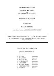
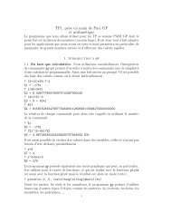
<strong>Electrical</strong> <strong>conduction</strong> <strong>in</strong> cha<strong>in</strong>s <strong>of</strong> beadsTable 2 Quantities correspond<strong>in</strong>g to the experimental characteristicsU–I <strong>of</strong> Figs. 7 <strong>and</strong> 8—cha<strong>in</strong> <strong>of</strong> 3 sta<strong>in</strong>less beads (diameter 11 mm)1 2 3 4I MAX (A) 0.5 1 1.5 2α ↓ ∗ 10 −3 (K −1 ) 1.8 1.7 1.4 1.2α ↑ ∗ 10 −3 (K −1 ) 1.8 1.7 1.4 0.9T 0↓ (K) 295 315 365 440T 0↑ (K) 295 315 365 600Fig. 8 Voltage U as a function <strong>of</strong> current I for a cha<strong>in</strong> <strong>of</strong> 3 sta<strong>in</strong>lessbeads (diameter 11 mm) submitted to four successive cycles <strong>of</strong> current.Experimental data (multisymbol), analytical model (solid l<strong>in</strong>es) correspond<strong>in</strong>gto Eqs. 6 <strong>and</strong> 8. Parameters <strong>of</strong> the fit are given <strong>in</strong> Table 3.Analyticalmodel from Falcon et al. (Eq. (8) <strong>in</strong> Ref. [14]) with α −1 = 1.9 T 0(Table 2 gives the evolution <strong>of</strong> T 0 ): (dashed l<strong>in</strong>es with dotted) <strong>in</strong>creas<strong>in</strong>gcurrents <strong>and</strong> (dashed l<strong>in</strong>es) decreas<strong>in</strong>g currentsbetween model <strong>and</strong> experiments for low electric currentsI MAX = 0.5 A.Fortheothercycles<strong>of</strong>electriccurrent,thetemperature T 0 is adjusted to give the best agreement betweenmodel <strong>and</strong> experiments. The results are gathered <strong>in</strong> Table 2.The values <strong>of</strong> α are sensibly smaller than those from modelEq. 8 <strong>and</strong> decrease a little faster with I MAX .Thismodelpredictsalso anomalously high temperatures T 0 .Figure8 showsthat with <strong>in</strong>creas<strong>in</strong>g I MAX ,themodel[13,14] deviatessignificantlyfrom the experimental cycles. Although the experimentalU–I characteristics can be well fitted by the modelsEqs. 6 <strong>and</strong> 8 (see Fig. 8), there exist disagreements on theobta<strong>in</strong>ed parameters from the both preced<strong>in</strong>g models (seeparameter values <strong>in</strong> Table 1 <strong>and</strong> especially the temperatureT 0 ). This shows the failure <strong>of</strong> these models to describe correctlythe electro-thermo-mechanical behavior <strong>of</strong> a cha<strong>in</strong> <strong>of</strong>Table 1 Quantities correspond<strong>in</strong>g to the experimental characteristicsU–I <strong>of</strong> Figs. 7 <strong>and</strong> 8—cha<strong>in</strong> <strong>of</strong> 3 sta<strong>in</strong>less beads (diameter 11 mm)1 2 3 4I MAX (A) 0.5 1 1.5 2R lc↓ () 1.09 0.58 0.43 0.35R lc↑ () 1.08 0.58 0.44 0.41α ↓ ∗ 10 −3 (K −1 ) 2.4 2.3 2.0 2.0α ↑ ∗ 10 −3 (K −1 ) 2.4 2.2 1.9 1.5T 0↓ (K) 543 601 702 968T 0↑ (K) 513 544 632 1071The parameters R lc , α (related to electrical resistivity) <strong>and</strong> T 0 are providedby the simplified model Eq. 8 us<strong>in</strong>g a nonl<strong>in</strong>ear m<strong>in</strong>imizationrout<strong>in</strong>e. Quantities for <strong>in</strong>creas<strong>in</strong>g current are R lc↑ , α ↑ <strong>and</strong> T 0↑ ; quantitiesfor decreas<strong>in</strong>g current are R lc↓ , α↓ <strong>and</strong> T 0↓The model <strong>of</strong> Falcon et al. [13,14] withα −1 = 1.9 T 0 is used. Quantitiesfor <strong>in</strong>creas<strong>in</strong>g current are α ↑ <strong>and</strong> T 0↑ ; quantities for decreas<strong>in</strong>gcurrent are α↓ <strong>and</strong> T 0↓beads carry<strong>in</strong>g various currents <strong>and</strong> submitted to a weak force∼ 1N.4.1.2 Extended modelUnder these conditions, the ‘extended’ model (Eq. 6) describedpreviously must be considered. Parameters A, B <strong>and</strong>Carenowidentifiedtothecorrespond<strong>in</strong>gterms<strong>of</strong>therelationbetween current <strong>and</strong> voltage (Eq. 6). Us<strong>in</strong>g the resistanceR lc evaluated through the slope <strong>of</strong> the U–I plot at low current<strong>and</strong> assum<strong>in</strong>g α(T 0 − T r ) ≪ 1 (a realistic assumption),quantities α <strong>and</strong> β can be estimated. Table 3 gives the evolutions<strong>of</strong> these quantities for cycles <strong>of</strong> electric current (seeFig. 7).For all the cycles <strong>of</strong> electric current, parameters α arepositive <strong>and</strong> β negative. The obta<strong>in</strong>ed values are close toα ≃ 6×10 −3 K −1 <strong>and</strong> 2×10 −4 ≤ β ≤ 12×10 −4 K −1 givenby reference [12] forvarioussolid/solidcontactsbetweenmetals (Al, Ni, Fe) <strong>and</strong> α ≃ 1.6 × 10 −3 K −1 given <strong>in</strong>Table 3 Quantities correspond<strong>in</strong>g to the characteristics U–I <strong>of</strong> Fig. 7—cha<strong>in</strong> <strong>of</strong> 3 sta<strong>in</strong>less beads (diameter 11 mm)1 2 3 4I MAX (A) 0.5 1 1.5 2U MAX (V) 0.93 0.98 1.05 1.1R lc↓ () 1.09 0.58 0.43 0.36R lc↑ () 1.09 0.58 0.44 0.42α ↓ ∗ 10 −3 (K −1 ) 2.2 1.9 1.4 1.0α ↑ ∗ 10 −3 (K −1 ) 2.3 2.0 1.5 0.7β ↓ ∗ 10 −4 (K −1 ) −5.2 −5.0 −4.2 −4.8β ↑ ∗ 10 −4 (K −1 ) −4.3 −3.6 −2.7 −2.5R lc is obta<strong>in</strong>ed from the slope <strong>of</strong> the U–I curve at low current. Parametersα (connected to the electrical resistivity) <strong>and</strong> β (connected to thethermal conductivity) are provided by Eq. 6 us<strong>in</strong>g a nonl<strong>in</strong>ear m<strong>in</strong>imizationrout<strong>in</strong>e. Quantities for <strong>in</strong>creas<strong>in</strong>g current are R lc↑ , α ↑ <strong>and</strong> β ↑ ;quantities for decreas<strong>in</strong>g current are R lc↓ , α ↓ <strong>and</strong> β ↓123
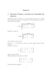
P. Béqu<strong>in</strong>, V. TournatRef. [22] forasta<strong>in</strong>lesssteelAISI420.Thus,an<strong>in</strong>crease<strong>in</strong> temperature when large currents pass through the contactregion between beads leads to an <strong>in</strong>crease <strong>in</strong> the electricalresistivity ρ <strong>and</strong> to a decrease <strong>in</strong> the thermal conductivityλ with<strong>in</strong> the contact<strong>in</strong>g material. Consequently a rise<strong>in</strong> temperature <strong>in</strong>creases resistivity—<strong>and</strong> <strong>Joule</strong> <strong>effect</strong>—<strong>and</strong>decreases thermal conductivity—which reduces the ability<strong>of</strong> the material to dissipate heat by thermal <strong>conduction</strong>. Inthe contact region between beads it is sufficient to cause asignificant heat accumulation. Moreover, it can be observedthat the saturation voltage U MAX <strong>in</strong>creases with the maximumcurrent I MAX .Consequently,thetemperatureatthecontact surface <strong>in</strong>creases <strong>and</strong> tends gradually towards themelt<strong>in</strong>g temperature <strong>of</strong> the contact<strong>in</strong>g material. A s<strong>of</strong>ten<strong>in</strong>g<strong>of</strong> the asperities is expected [13], <strong>and</strong> can lead to alocal micro-s<strong>in</strong>ter<strong>in</strong>g. As a result, the electrical resistivityis found to decrease with current I MAX (α decreases) <strong>and</strong>the thermal conductivity <strong>in</strong>creases with current I MAX (|β|decreases).For a cycle <strong>of</strong> electric current, coefficients α ↑ (<strong>in</strong>creas<strong>in</strong>gcurrent) <strong>and</strong> α ↓ (decreas<strong>in</strong>g current) present roughly equalvalues; <strong>in</strong> contrast coefficients β ↑ <strong>and</strong> β ↓ <strong>of</strong> thermal conductivityhave different values (|β ↓ | > |β ↑ |)thatmeasurementuncerta<strong>in</strong>ty cannot expla<strong>in</strong> al<strong>one</strong>. In model Eq. 6, thedependencies <strong>of</strong> electrical resistivity <strong>and</strong> thermal conductivityon temperature are considered l<strong>in</strong>ear (Eq. 5) overthewhole range <strong>of</strong> temperature (293–1800 K). On the basis <strong>of</strong>the presented results, <strong>one</strong> improvement could be to seek moreelaborated relations for ρ(T ) <strong>and</strong> λ(T ). Thedependenciescan be expressed as a power series <strong>of</strong> temperature T withmore terms than used <strong>in</strong> models [12,27]. Furthermore, it is<strong>in</strong>terest<strong>in</strong>g to note that a positive value <strong>of</strong> β ↑ for the <strong>in</strong>creas<strong>in</strong>gcurrents is deduced from Fig. 6. A thorough analysis <strong>of</strong>the experimental curve shows a po<strong>in</strong>t <strong>of</strong> <strong>in</strong>flection close toI = 0.44 A. This change <strong>of</strong> behavior could be ascribed toan <strong>in</strong>itial s<strong>of</strong>ten<strong>in</strong>g <strong>of</strong> the contact surface when the currentgrows, <strong>and</strong> could partly expla<strong>in</strong> the difference with the values<strong>in</strong> Table 3. The role <strong>of</strong> the latent heat <strong>in</strong> the possiblemicro-melt<strong>in</strong>g <strong>of</strong> the asperities is a highly complex phenomenonto model at this level <strong>of</strong> underst<strong>and</strong><strong>in</strong>g. It has notbeen taken <strong>in</strong>to account <strong>in</strong> the presented models: all the estimatedtemperatures rema<strong>in</strong> significantly lower than the melt<strong>in</strong>gpo<strong>in</strong>t. Only s<strong>of</strong>ten<strong>in</strong>g <strong>of</strong> the contacts <strong>and</strong> micro-s<strong>in</strong>ter<strong>in</strong>ghave been <strong>in</strong>voked here to <strong>in</strong>terpret the results. The study<strong>of</strong> the micro-structural changes <strong>of</strong> the contact areas by othermeans could be pr<strong>of</strong>itable to guide the future improvements<strong>of</strong> the models.In conclusion, these measurements show the diversity <strong>of</strong>electrical <strong>and</strong> thermal phenomena with<strong>in</strong> the cha<strong>in</strong>s <strong>of</strong> beads.The simplified models based on the Wiedemann–Franz’slaw fail to describe the electro-thermo-mechanical phenomena<strong>in</strong> a cha<strong>in</strong> <strong>of</strong> beads carry<strong>in</strong>g currents under a small appliedcompression force ∼1 N.5Electromagnetic<strong>effect</strong>sonacha<strong>in</strong><strong>of</strong>beadsThe l<strong>in</strong>ear <strong>and</strong> nonl<strong>in</strong>ear acoustic properties <strong>of</strong> granular materialsare strongly sensitive to the mechanical properties at thelevel <strong>of</strong> the contacts between beads [4]. For such studies, itcould be extremely convenient to be able to modify contactmechanical properties without any modification <strong>of</strong> the geometry<strong>of</strong> the medium. A controlled electromagnetic wave hasthe ability to produce these mechanical transformations withoutaffect<strong>in</strong>g the rema<strong>in</strong>der <strong>of</strong> the granular structure. In thiscontext, <strong>and</strong> as a complement to the previous part, this sectionreports an analysis <strong>of</strong> the electrical <strong>and</strong> thermal behaviors <strong>of</strong>acha<strong>in</strong><strong>of</strong>beadssubjectedtoastrongelectromagneticpulsecreated by a spark.This study can be viewed as a cont<strong>in</strong>uation <strong>of</strong> the work<strong>of</strong> Dorbolo et al. [21] whichwasdeal<strong>in</strong>gwiththe<strong>in</strong>fluence<strong>of</strong> an electromagnetic wave on the electrical resistance <strong>of</strong>the contacts between two beads. In [21], the electromagneticperturbation is found to affect preferentially the contacts hav<strong>in</strong>ga resistance higher than a threshold value which dependsma<strong>in</strong>ly on both the mechanical characteristics <strong>of</strong> the cha<strong>in</strong> <strong>of</strong>beads <strong>and</strong> <strong>of</strong> the distance between the latter <strong>and</strong> the spark (theelectromagnetic source). Here, we carry out measurementswith a near field electromagnetic excitation. They confirmpartly <strong>and</strong> extend the observations <strong>of</strong> Ref. [21] made<strong>in</strong>thefar field.5.1 Experimental set-upThe experimental set-up is presented <strong>in</strong> Fig. 9. Theelectromagneticwave is produced by a discharge across a spark gapas <strong>in</strong> Refs. [17,28].Experiments were performed us<strong>in</strong>g a “three-electrode system”<strong>in</strong> which the storage capacitor is kept charged at a voltage(from 0 to 20 kV) lower than the breakdown voltage <strong>of</strong>the gap <strong>in</strong> air at atmospheric conditions. A third electrodeis placed between the ma<strong>in</strong> electrodes to provide an <strong>in</strong>itialionization <strong>of</strong> the air necessary to cause the spark breakdownmechanism.5.2 ResultsFigure 10 shows the voltage–current characteristics for acycle <strong>of</strong> current (0–1 A). Dur<strong>in</strong>g this cycle, 5 sparks are created(distance between the cha<strong>in</strong> <strong>of</strong> beads <strong>and</strong> the electrodesr ≃ 120 mm) caus<strong>in</strong>g a voltage drop between the electrodes<strong>of</strong> the cha<strong>in</strong> <strong>of</strong> beads. These voltage drops can be connectedto strong variations <strong>of</strong> the contact impedances. It is observedthat for <strong>in</strong>creas<strong>in</strong>g dc currents I ,theelectricbehavior<strong>of</strong>thecha<strong>in</strong> <strong>of</strong> beads is less <strong>and</strong> less disturbed by the electromagneticpulses.The electromagnetic radiation created by these sparks<strong>in</strong>duces an electric current I sp <strong>in</strong> the cha<strong>in</strong> <strong>of</strong> beads which is123
<strong>Electrical</strong> <strong>conduction</strong> <strong>in</strong> cha<strong>in</strong>s <strong>of</strong> beadsFig. 11 Diameter <strong>of</strong> the contact d versus current I deduced from theellipsoidal model for the contact surface. Solid curve: model I U = d ρ —Eq. 2. Cha<strong>in</strong> <strong>of</strong> 5 sta<strong>in</strong>less beads (diameter 11 mm). Dur<strong>in</strong>g the cycle<strong>of</strong> current, 5 sparks were created; r ≃ 120 mm distance between thecha<strong>in</strong> <strong>of</strong> bead <strong>and</strong> the sparkFig. 9 Schematic diagram <strong>of</strong> the experimental set-up to study the <strong>in</strong>fluence<strong>of</strong> an electromagnetic wave pulse on the electromechanical behavior<strong>of</strong> a cha<strong>in</strong> <strong>of</strong> beads. A “three-electrode system” is used for the generation<strong>of</strong> the electromagnetic pulse. V T <strong>and</strong> V HT are the trigger voltage<strong>and</strong> the capacitor voltage. The gap distance is 10 mm <strong>and</strong> r is the distancebetween the axis <strong>of</strong> the discharge <strong>and</strong> the axis <strong>of</strong> the cha<strong>in</strong> <strong>of</strong>beadsFig. 12 Induced current I sp versus distance r between the cha<strong>in</strong> <strong>of</strong>beads <strong>and</strong> the spark. Values estimated at I ≃ 0.5 Adur<strong>in</strong>gacycle<strong>of</strong>current (0–0.5 A) on a cha<strong>in</strong> <strong>of</strong> 5 sta<strong>in</strong>less beads (diameter 11 mm).Dashed l<strong>in</strong>e corresponds to I sp ∝ 1/r 2.1Fig. 10 Voltage U as a function <strong>of</strong> current I . Cha<strong>in</strong> <strong>of</strong> 5 sta<strong>in</strong>less beads(diameter 11 mm). Dur<strong>in</strong>g the cycle <strong>of</strong> current, 5 sparks are produced<strong>and</strong> are <strong>in</strong>dicated by the arrows. The distance between the cha<strong>in</strong> <strong>of</strong>beads <strong>and</strong> the spark is r ≃ 120 mmadded <strong>in</strong> a quadratic way to the dc current I due to the fact thatthey are <strong>in</strong>coherent current sources. Us<strong>in</strong>g the model fromEq. 2 giv<strong>in</strong>g the diameter <strong>of</strong> the contact as a function <strong>of</strong> theadmittance I U = d ρ ,thecontactdiameterisplottedasafunction<strong>of</strong> the current <strong>in</strong> Fig. 11.Thecurrentpulse<strong>in</strong>ducedbytheelectromagnetic pulse contributes to the sudden rise <strong>of</strong> thecontact diameter between beads. After this sudden <strong>in</strong>crease,the diameter rema<strong>in</strong>s constant as long as the dc current Ican flow without modify<strong>in</strong>g the area <strong>of</strong> contact by s<strong>of</strong>ten<strong>in</strong>g[9–11,21].The value <strong>of</strong> the impulse current I sp can be estimated byidentification to the value <strong>of</strong> the dc current I necessary toobta<strong>in</strong> the same diameter <strong>of</strong> contact. With this method, the<strong>in</strong>duced current I sp for the first spark (data correspond<strong>in</strong>g toFigs. 10 <strong>and</strong> 11)isestimatedtobearound0.35 A. In this currentcycle, for dc currents higher than 0.9 A, the presence <strong>of</strong><strong>in</strong>duced impulse currents does not further modify the contactgeometry between the beads. As was previously observed <strong>in</strong>[21], the Fig. 11 shows that the contacts hav<strong>in</strong>g a small diameter<strong>and</strong> thus a high electrical resistance (U I = ρ d —Eq. 2)arestrongly affected by the electromagnetic perturbation.Figure 12 gives the current <strong>in</strong>duced by the electromagneticpulse <strong>of</strong> a spark placed at a distance r from a cha<strong>in</strong> <strong>of</strong> 5 beads.The values <strong>of</strong> this current are estimated us<strong>in</strong>g the methoddescribed previously. This figure shows that the <strong>in</strong>duced currentdecreases monotonically as distance r <strong>in</strong>creases. A firstanalysis at the distances r higher than 50 mm (distances123
P. Béqu<strong>in</strong>, V. Tournatroughly equal or larger than the length <strong>of</strong> the cha<strong>in</strong> <strong>of</strong> beads:5 × 11 mm) shows that the current <strong>in</strong>duced by the spark isproportional to 1/r 2.1 (obta<strong>in</strong>ed through a l<strong>in</strong>ear regressionon log[I sp ]). These results are consistent with those obta<strong>in</strong>ed<strong>in</strong> [21] wherean<strong>in</strong>ducedcurrentproportionalto1/r m withm ≃ 1.2 fordistancesr vary<strong>in</strong>g between 0.1 <strong>and</strong> 2.2 mis observed. Note that the spatial dependence <strong>of</strong> monochromaticelectromagnetic wave amplitude is respectively proportionalto 1/r 2 <strong>in</strong> the near field <strong>and</strong> proportional to 1/r <strong>in</strong>the far field.At this level, the lack <strong>of</strong> <strong>in</strong>formation on the electromagneticfield (amplitude, frequency spectrum <strong>and</strong> directivity)does not allow the development <strong>of</strong> a realistic model to becompared to experimental results. These particular electromagneticbehaviors as a function <strong>of</strong> distance (near field/farfield) will have to be taken <strong>in</strong>to account <strong>in</strong> the models <strong>and</strong>experiments dedicated to the electromechanical behavior <strong>of</strong>agranularmediumwithlargedimensions.6ConclusionCont<strong>in</strong>ued <strong>in</strong>terest <strong>in</strong> granular materials has stimulated newexperiments <strong>and</strong> models to characterize these complex structures.In this article the electrical <strong>and</strong> thermal behaviors <strong>of</strong> acha<strong>in</strong> <strong>of</strong> beads carry<strong>in</strong>g a dc <strong>and</strong> an impulse electric currenthave been <strong>in</strong>vestigated. This work provides theoretical <strong>and</strong>experimental cont<strong>in</strong>uations to the studies <strong>of</strong> Refs. [13,14,21]mostly carried out <strong>in</strong> the context <strong>of</strong> the Branly <strong>effect</strong>.The passage <strong>of</strong> an electric current <strong>in</strong> a cha<strong>in</strong> <strong>of</strong> beadsaffects the nature <strong>of</strong> the contact between beads by caus<strong>in</strong>gaheat<strong>in</strong>g<strong>and</strong>as<strong>of</strong>ten<strong>in</strong>g<strong>of</strong>themetalnearthe<strong>in</strong>terface.These changes are consequent to the heat which is generated<strong>in</strong> the constricted region <strong>of</strong> the current flow <strong>and</strong> lead to an<strong>in</strong>crease <strong>in</strong> the contact surface. We developed specifically anexperimental setup suited to the measurement <strong>of</strong> the electriccurrent <strong>and</strong> voltage for a cha<strong>in</strong> <strong>of</strong> metallic beads. The analysis<strong>of</strong> the voltage–current characteristics <strong>of</strong> such a cha<strong>in</strong><strong>in</strong>dicates that the diameter <strong>of</strong> the contact surface varies l<strong>in</strong>earlywith electric current I .Subjectedtoacycliccurrent,the cha<strong>in</strong> <strong>of</strong> beads presents an electromechanical behavior<strong>of</strong> hysteretic type. The larger are the electric current <strong>and</strong> thenumber <strong>of</strong> beads the larger is the hysteretic <strong>effect</strong> (the loop)<strong>and</strong> the greater is the heat released <strong>in</strong> the cha<strong>in</strong>.Steady states models derived on the assumption <strong>of</strong> equilibriumbetween <strong>Joule</strong> heat<strong>in</strong>g <strong>in</strong> the contact area <strong>and</strong>thermal dissipation by <strong>conduction</strong> with<strong>in</strong> the material areproposed. The simplified models <strong>of</strong> Eq. 8 <strong>and</strong> the modeldeveloped <strong>in</strong> [13,14], all based on the Wiedemann–Franz’slaw (W–F) (which states that the product <strong>of</strong> the thermal conductivity<strong>and</strong> the electrical resistivity <strong>of</strong> a metal is proportionalto the temperature), are observed to be <strong>in</strong>adequate todescribe electromechanical <strong>conduction</strong> <strong>in</strong> cha<strong>in</strong>s <strong>of</strong> beadswith cyclic currents under a weak static compression force∼1N.AnextendedmodelEq.6 is then developed without therestrictions <strong>of</strong> the W–F’s law. The comparisons with experimentaldata provide the variations <strong>of</strong> parameters α <strong>and</strong> βcorrespond<strong>in</strong>g respectively to the l<strong>in</strong>ear evolution <strong>of</strong> the electricalresistivity <strong>and</strong> to the thermal conductivity (Eq. 5). Theseresults could benefit <strong>in</strong> the future from temperature measurementson the beads <strong>and</strong> from the use <strong>of</strong> various materials <strong>and</strong>bead diameters.The <strong>effect</strong> <strong>of</strong> an electromagnetic pulse produc<strong>in</strong>g a pulse<strong>of</strong> electric current through a cha<strong>in</strong> <strong>of</strong> beads is f<strong>in</strong>ally studied.The electromagnetic wave pulse is created by an electric discharge(electric spark) placed near the cha<strong>in</strong> <strong>of</strong> beads. Theexperimental results show that the current can cause appreciablechanges <strong>in</strong> the contact surface when the magnitude <strong>of</strong>the <strong>in</strong>duced current is sufficient but also when the dccurrent rema<strong>in</strong> weak. Evolution <strong>of</strong> the <strong>in</strong>duced current withthe cha<strong>in</strong>/spark distance <strong>in</strong> near field (100 mm) <strong>in</strong> Ref.[21] wherethe1/r dependence is observed.The control <strong>of</strong> the contact surface between beads us<strong>in</strong>gasuitableelectromagneticwavecouldf<strong>in</strong>dapplications<strong>in</strong>particular <strong>in</strong> the study <strong>of</strong> the fundamental processes <strong>in</strong>volved<strong>in</strong> the acoustic propagation through granular media [29–32].Acknowledgments We would like to thank James Blondeau, StéphaneLebon <strong>and</strong> Eric Egon for their assistance <strong>in</strong> the experiments <strong>and</strong>their technical advice. We particularly thank Jean-Marie Genet for hisexperimental work.References1. Duran, J.: S<strong>and</strong>s, Powders <strong>and</strong> Gra<strong>in</strong>s. Spr<strong>in</strong>ger-Verlag, NewYork (1999)2. Kakalios, J.: Granular physics or nonl<strong>in</strong>ear dynamics <strong>in</strong> a s<strong>and</strong>box.Am. J. Phys. 73(1), 8–22 (2005)3. Nesterenko, V.F.: Dynamics <strong>of</strong> Heterogeneous Materials. Spr<strong>in</strong>ger-Verlag, New York (2001)4. Tournat, V., Zaitsev, V., Gusev, V., Nazarov, V., Béqu<strong>in</strong>, P.,Castagnède, B.: Prob<strong>in</strong>g weak forces <strong>in</strong> granular media throughnonl<strong>in</strong>ear dynamic dilatancy: clapp<strong>in</strong>g contacts <strong>and</strong> polarizationanisotropy. Phys. Rev. Lett. 92, 085502(2004)5. Sen, S., Hong, J., Avalos, E., D<strong>one</strong>y, R.: Solitary waves <strong>in</strong> thegranular cha<strong>in</strong>. Phys. Rep. 462, 21–66(2008)6. Johnson, K.L.: Contact Mechanics. Cambridge UniversityPress, Cambridge (1985)7. Holm, R.: Electric Contacts, 3rd edn. Spr<strong>in</strong>ger, Berl<strong>in</strong> (2000)8. Féchant, L.: Le contact électrique. Hermès, Paris (1996)9. Bowden, F.P., Williamson, J.B.P.: <strong>Electrical</strong> <strong>conduction</strong> <strong>in</strong> solids.Part I: <strong>in</strong>fluence <strong>of</strong> the passage <strong>of</strong> current on the contact betweensolids. Proc. R. Soc. Lond. Ser. A 246(1244), 1–12 (1958)10. Greenwood, J.A., Williamson, J.B.P.: <strong>Electrical</strong> <strong>conduction</strong> <strong>in</strong> solids.Part II: theory <strong>of</strong> temperature-dependent conductors. Proc. R.Soc. Lond. Ser. A 246(1244), 13–31 (1958)123
<strong>Electrical</strong> <strong>conduction</strong> <strong>in</strong> cha<strong>in</strong>s <strong>of</strong> beads11. Greenwood, J.A., Harris, J.: <strong>Electrical</strong> <strong>conduction</strong> <strong>in</strong> solids.Part III: the contact <strong>of</strong> iron surfaces. Proc. R. Soc. Lond. Ser.A 257(1288), 83–97 (1960)12. Timsit, R.S. : Ch.1 electrical contact resistance: fundamental pr<strong>in</strong>ciples.In: Slade, P.G. <strong>Electrical</strong> Contacts—Pr<strong>in</strong>ciples <strong>and</strong> Applications,CRC Press, New York (1999)13. Falcon, E., Casta<strong>in</strong>g, B., Creyssels, M.: Nonl<strong>in</strong>ear electrical conductivity<strong>in</strong> a 1D granular medium. Eur. Phys. J. B 38, 475–483 (2004)14. Falcon, E., Casta<strong>in</strong>g, B.: <strong>Electrical</strong> conductivity <strong>in</strong> granularmedia <strong>and</strong> Branly’s coherer: a simple experiment. Am. J.Phys. 73(4), 302–307 (2005)15. Gém<strong>in</strong>ard, J.-C., Bouraya, D., Gayvallet, H.: Thermal conductivityassociated with a bead-bead contact decorated by a liquidbridge. Eur. Phys. J. B 48, 509–517(2005)16. Creyssels, M., Dorbolo, S., Merlen, A., Laroche, C., Casta<strong>in</strong>g, B.,Falcon, E.: Some aspects <strong>of</strong> electrical <strong>conduction</strong> <strong>in</strong> granular systems<strong>of</strong> various dimensions. Eur. Phys. J. E 23, 255–264(2007)17. Raizer, Y.P.: Gas Discharge Physics. Spr<strong>in</strong>ger-Verlag,Berl<strong>in</strong> (1991)18. Dorbolo, S., Ausloos, M., V<strong>and</strong>ewalle, N.: Hysteretic behavior <strong>in</strong>metallic granular matter. Appl. Phys. Lett. 81(5), 936–938 (2002)19. Dorbolo, S., Ausloos, M., V<strong>and</strong>ewalle, N., Houssa, M.: Ag<strong>in</strong>g process<strong>of</strong> electrical contacts <strong>in</strong> granular matter. Appl. Phys. Lett. 94,1040302(R) (2003)20. Dorbolo, S., Ausloos, M., V<strong>and</strong>ewalle, N.: Reexam<strong>in</strong>ation <strong>of</strong> theBranly <strong>effect</strong>. Phys. Rev. E 67(12), 7835–7838 (2003)21. Dorbolo, S., Merlen, A., Creyssels, M., V<strong>and</strong>ewalle, N., Casta<strong>in</strong>g,B., Falcon, E.: Effects <strong>of</strong> electromagnetic waves on the electricalproperties <strong>of</strong> contacts between gra<strong>in</strong>s. EPL 79(54001), 7835–7838 (2007)22. Davis, J.R. (ed.): ASM Specialty H<strong>and</strong>book: Sta<strong>in</strong>less Steels. ASMInternational, New York (1994)23. Omel’chenko, V.T.: Determ<strong>in</strong>ation <strong>of</strong> the excess temperature<strong>of</strong> electrical contacts with cont<strong>in</strong>ous current variation. J. Eng.Phys. 10(1), 45–47 (1966)24. Fournet, G.: Phenomena <strong>in</strong> conductors hav<strong>in</strong>g temperature dependentelectrical <strong>and</strong> thermal conductivities. J. Phys. III 7, 2003–2029 (1997)25. European Sta<strong>in</strong>less Steel Development Association.: Sta<strong>in</strong>lessSteel: Tables <strong>of</strong> Technical Properties. http://www.euro-<strong>in</strong>ox.org(2000)26. Gale, W.F., Totemeir, T.C. (eds.): Smithells Metals ReferenceBook, 8th edn. ASM International, London (2004)27. Tan, X., Conway, P.P., Sarvar, F.: Thermo-mechanical properties<strong>and</strong> regression models <strong>of</strong> alloys: AISI 305, CK 60, CuBe 2 <strong>and</strong>laiton MS 63. J. Mater. Process. Technol. 168, 152–163(2005)28. Ayrault, C., Béqu<strong>in</strong>, P., Legros, M.: Experimental study <strong>of</strong> a sparkdischarge as an acoustic source. In: Proceed<strong>in</strong>gs <strong>of</strong> 19th InternationalCongress on Acoustics. I.C.A., Madrid, Spa<strong>in</strong> (2007)29. Job, S., Melo, F., Sokolow, A., Sen, S.: How hertzian solitarywaves <strong>in</strong>teract with boundaries <strong>in</strong> a 1d granular medium. Phys.Rev. Lett. 94, 178002(2005)30. Daraio, C., Nesterenko, V.F., Herbold, E.B., J<strong>in</strong>, S.: Stronglynonl<strong>in</strong>ear waves <strong>in</strong> a cha<strong>in</strong> <strong>of</strong> teflon beads. Phys. Rev.E 72, 016603(2005)31. Hladky-Hennion, A.-C., de Billy, M.: Experimental validation <strong>of</strong>b<strong>and</strong> gaps <strong>and</strong> localization <strong>in</strong> a <strong>one</strong>-<strong>dimensional</strong> diatomic phononiccrystal. J. Acoust. Soc. Am. 122, 2594–2600(2007)32. Porter, M.A., Daraio, C., Herbold, E.B., Szelengowicz, I., Kevrekidis,P.G.: Highly nonl<strong>in</strong>ear solitary waves <strong>in</strong> phononic crystaldimers. Phys. Rev. E 77, 015601(R)(2008)123