high lifetime on n-type silicon wafers obtained - ISC Konstanz
high lifetime on n-type silicon wafers obtained - ISC Konstanz
high lifetime on n-type silicon wafers obtained - ISC Konstanz

You also want an ePaper? Increase the reach of your titles
YUMPU automatically turns print PDFs into web optimized ePapers that Google loves.
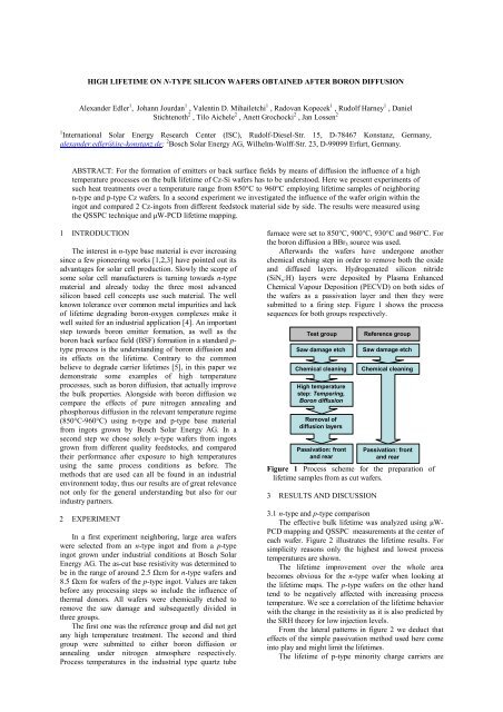
HIGH LIFETIME ON N-TYPE SILICON WAFERS OBTAINED AFTER BORON DIFFUSIONAlexander Edler 1 , Johann Jourdan 1 , Valentin D. Mihailetchi 1 , Radovan Kopecek 1 , Rudolf Harney 1 , DanielStichtenoth 2 , Tilo Aichele 2 , Anett Grochocki 2 , Jan Lossen 21 Internati<strong>on</strong>al Solar Energy Research Center (<strong>ISC</strong>), Rudolf-Diesel-Str. 15, D-78467 K<strong>on</strong>stanz, Germany,alexander.edler@isc-k<strong>on</strong>stanz.de; 2 Bosch Solar Energy AG, Wilhelm-Wolff-Str. 23, D-99099 Erfurt, Germany.ABSTRACT: For the formati<strong>on</strong> of emitters or back surface fields by means of diffusi<strong>on</strong> the influence of a <str<strong>on</strong>g>high</str<strong>on</strong>g>temperature processes <strong>on</strong> the bulk <str<strong>on</strong>g>lifetime</str<strong>on</strong>g> of Cz-Si <strong>wafers</strong> has to be understood. Here we present experiments ofsuch heat treatments over a temperature range from 850°C to 960°C employing <str<strong>on</strong>g>lifetime</str<strong>on</strong>g> samples of neighboringn-<strong>type</strong> and p-<strong>type</strong> Cz <strong>wafers</strong>. In a sec<strong>on</strong>d experiment we investigated the influence of the wafer origin within theingot and compared 2 Cz-ingots from different feedstock material side by side. The results were measured usingthe QSSPC technique and µW-PCD <str<strong>on</strong>g>lifetime</str<strong>on</strong>g> mapping.1 INTRODUCTIONThe interest in n-<strong>type</strong> base material is ever increasingsince a few pi<strong>on</strong>eering works [1,2,3] have pointed out itsadvantages for solar cell producti<strong>on</strong>. Slowly the scope ofsome solar cell manufacturers is turning towards n-<strong>type</strong>material and already today the three most advancedsilic<strong>on</strong> based cell c<strong>on</strong>cepts use such material. The wellknown tolerance over comm<strong>on</strong> metal impurities and lackof <str<strong>on</strong>g>lifetime</str<strong>on</strong>g> degrading bor<strong>on</strong>-oxygen complexes make itwell suited for an industrial applicati<strong>on</strong> [4]. An importantstep towards bor<strong>on</strong> emitter formati<strong>on</strong>, as well as thebor<strong>on</strong> back surface field (BSF) formati<strong>on</strong> in a standard p-<strong>type</strong> process is the understanding of bor<strong>on</strong> diffusi<strong>on</strong> andits effects <strong>on</strong> the <str<strong>on</strong>g>lifetime</str<strong>on</strong>g>. C<strong>on</strong>trary to the comm<strong>on</strong>believe to degrade carrier <str<strong>on</strong>g>lifetime</str<strong>on</strong>g>s [5], in this paper wedem<strong>on</strong>strate some examples of <str<strong>on</strong>g>high</str<strong>on</strong>g> temperatureprocesses, such as bor<strong>on</strong> diffusi<strong>on</strong>, that actually improvethe bulk properties. Al<strong>on</strong>gside with bor<strong>on</strong> diffusi<strong>on</strong> wecompare the effects of pure nitrogen annealing andphosphorous diffusi<strong>on</strong> in the relevant temperature regime(850°C-960°C) using n-<strong>type</strong> and p-<strong>type</strong> base materialfrom ingots grown by Bosch Solar Energy AG. In asec<strong>on</strong>d step we chose solely n-<strong>type</strong> <strong>wafers</strong> from ingotsgrown from different quality feedstocks, and comparedtheir performance after exposure to <str<strong>on</strong>g>high</str<strong>on</strong>g> temperaturesusing the same process c<strong>on</strong>diti<strong>on</strong>s as before. Themethods that are used can all be found in an industrialenvir<strong>on</strong>ment today, thus our results are of great relevancenot <strong>on</strong>ly for the general understanding but also for ourindustry partners.2 EXPERIMENTIn a first experiment neighboring, large area <strong>wafers</strong>were selected from an n-<strong>type</strong> ingot and from a p-<strong>type</strong>ingot grown under industrial c<strong>on</strong>diti<strong>on</strong>s at Bosch SolarEnergy AG. The as-cut base resistivity was determined tobe in the range of around 2.5 Ωcm for n-<strong>type</strong> <strong>wafers</strong> and8.5 Ωcm for <strong>wafers</strong> of the p-<strong>type</strong> ingot. Values are takenbefore any processing steps so include the influence ofthermal d<strong>on</strong>ors. All <strong>wafers</strong> were chemically etched toremove the saw damage and subsequently divided inthree groups.The first <strong>on</strong>e was the reference group and did not getany <str<strong>on</strong>g>high</str<strong>on</strong>g> temperature treatment. The sec<strong>on</strong>d and thirdgroup were submitted to either bor<strong>on</strong> diffusi<strong>on</strong> orannealing under nitrogen atmosphere respectively.Process temperatures in the industrial <strong>type</strong> quartz tubefurnace were set to 850°C, 900°C, 930°C and 960°C. Forthe bor<strong>on</strong> diffusi<strong>on</strong> a BBr 3 source was used.Afterwards the <strong>wafers</strong> have underg<strong>on</strong>e anotherchemical etching step in order to remove both the oxideand diffused layers. Hydrogenated silic<strong>on</strong> nitride(SiN x :H) layers were deposited by Plasma EnhancedChemical Vapour Depositi<strong>on</strong> (PECVD) <strong>on</strong> both sides ofthe <strong>wafers</strong> as a passivati<strong>on</strong> layer and then they weresubmitted to a firing step. Figure 1 shows the processsequences for both groups respectively.Test groupFigure 1Saw damage etchChemical cleaningHigh temperaturestep: Tempering,Bor<strong>on</strong> diffusi<strong>on</strong>Removal ofdiffusi<strong>on</strong> layersPassivati<strong>on</strong>: fr<strong>on</strong>tand rearFigure 1 Process scheme for the preparati<strong>on</strong> of<str<strong>on</strong>g>lifetime</str<strong>on</strong>g> samples from as cut <strong>wafers</strong>.3 RESULTS AND D<strong>ISC</strong>USSIONReference groupSaw damage etchChemical cleaningPassivati<strong>on</strong>: fr<strong>on</strong>tand rear3.1 n-<strong>type</strong> and p-<strong>type</strong> comparis<strong>on</strong>The effective bulk <str<strong>on</strong>g>lifetime</str<strong>on</strong>g> was analyzed using µW-PCD mapping and QSSPC measurements at the center ofeach wafer. Figure 2 illustrates the <str<strong>on</strong>g>lifetime</str<strong>on</strong>g> results. Forsimplicity reas<strong>on</strong>s <strong>on</strong>ly the <str<strong>on</strong>g>high</str<strong>on</strong>g>est and lowest processtemperatures are shown.The <str<strong>on</strong>g>lifetime</str<strong>on</strong>g> improvement over the whole areabecomes obvious for the n-<strong>type</strong> wafer when looking atthe <str<strong>on</strong>g>lifetime</str<strong>on</strong>g> maps. The p-<strong>type</strong> <strong>wafers</strong> <strong>on</strong> the other handtend to be negatively affected with increasing processtemperature. We see a correlati<strong>on</strong> of the <str<strong>on</strong>g>lifetime</str<strong>on</strong>g> behaviorwith the change in the resistivity as it is also predicted bythe SRH theory for low injecti<strong>on</strong> levels.From the lateral patterns in figure 2 we deduct thateffects of the simple passivati<strong>on</strong> method used here comeinto play and might limit the <str<strong>on</strong>g>lifetime</str<strong>on</strong>g>s.The <str<strong>on</strong>g>lifetime</str<strong>on</strong>g> of p-<strong>type</strong> minority charge carriers are
already initially lower, but especially <strong>on</strong> the processedReference Bor<strong>on</strong> 850°C Bor<strong>on</strong> 960°CN-<strong>type</strong>P-<strong>type</strong>100µs 1000µsFigure 2: µW-PCD <str<strong>on</strong>g>lifetime</str<strong>on</strong>g> mapping of the n-<strong>type</strong> (left)and p-<strong>type</strong> (right) <strong>wafers</strong> that received bor<strong>on</strong> diffusi<strong>on</strong>with the <str<strong>on</strong>g>lifetime</str<strong>on</strong>g> mapping of an initial wafer (withoutdiffusi<strong>on</strong>).samples. However even if we compensate for thedifference in the diffusivity coefficient of the electr<strong>on</strong>sand holes, significantly <str<strong>on</strong>g>high</str<strong>on</strong>g>er diffusi<strong>on</strong> lengths ofminority charge carriers, as can be seen in figure 3, aremeasured <strong>on</strong> n-<strong>type</strong> <strong>wafers</strong> after the <str<strong>on</strong>g>high</str<strong>on</strong>g> temperatureprocess. These results indicate that bor<strong>on</strong> diffusi<strong>on</strong> canbe performed without degrading bulk <str<strong>on</strong>g>lifetime</str<strong>on</strong>g> in anindustrial solar cell process, and it dem<strong>on</strong>strates <str<strong>on</strong>g>high</str<strong>on</strong>g><str<strong>on</strong>g>lifetime</str<strong>on</strong>g> and <str<strong>on</strong>g>high</str<strong>on</strong>g> temperature stability of n-<strong>type</strong> <strong>wafers</strong> asneeded in a potential applicati<strong>on</strong>. The solar cell resultsbased <strong>on</strong> these materials are presented at 2DO.2.2The substantial increase in <str<strong>on</strong>g>lifetime</str<strong>on</strong>g> <strong>on</strong> n-<strong>type</strong> substrates isobserved for both, samples with bor<strong>on</strong> diffusi<strong>on</strong> andFigure 3: Average values of effective <str<strong>on</strong>g>lifetime</str<strong>on</strong>g> of thepassivated wafer and corresp<strong>on</strong>ding diffusi<strong>on</strong> length,deducted from µW-PCD mapping of the n-<strong>type</strong>(circles) and p-<strong>type</strong> (squares) <strong>wafers</strong> that received anannealing or either bor<strong>on</strong> or POCl 3 diffusi<strong>on</strong> stepand reference group.tempered samples and can therefore not be attributed toan impurity gettering effect of bor<strong>on</strong> doped layers. Theresults for all temperatures are summarized in figure 3 inform of effective <str<strong>on</strong>g>lifetime</str<strong>on</strong>g> values and effective diffusi<strong>on</strong>lengths.3.2 Comparis<strong>on</strong> of ingot qualityHere we selected <strong>wafers</strong> from the top, middle andbottom regi<strong>on</strong> of two different n-doped Cz crystalsrespectively. Both crystals were intenti<strong>on</strong>ally doped togain a base resistivity of about 2.5 Ωcm. The differencebetween the crystals is the feedstock of different quality.One ingot was made from <str<strong>on</strong>g>high</str<strong>on</strong>g>er quality feedstock(hereafter A1) while the sec<strong>on</strong>d <strong>on</strong>e was made fromfeedstock of comparable quality as feedstock comm<strong>on</strong>lyused in to dates industry processes (hereafter B1).We were interested in a side by side comparis<strong>on</strong> of the<str<strong>on</strong>g>high</str<strong>on</strong>g> temperature effects <strong>on</strong> <str<strong>on</strong>g>lifetime</str<strong>on</strong>g> samples given thedifferent quality of the base material. The influence of theorigin of the wafer within the ingot was also underinvestigati<strong>on</strong>. Groups of <strong>wafers</strong> from the differentpositi<strong>on</strong>s were processed under the same c<strong>on</strong>diti<strong>on</strong>s. Infigure 4 we give a set of exemplary results from bothingots and all <str<strong>on</strong>g>high</str<strong>on</strong>g> temperature processes. Here we limitourselves to the the depicti<strong>on</strong> of the middle regi<strong>on</strong> ofboth ingots but corresp<strong>on</strong>ding results have been found insamples from other parts of the respective ingot. Thesamples were prepared following the process sequenceoutlined in secti<strong>on</strong> 2.Reference P-Diffus. Tempering Bor<strong>on</strong> 960°CB1 ingotA1 ingot150µ 700µ
Figure 4: µW-PCD <str<strong>on</strong>g>lifetime</str<strong>on</strong>g> mapping of samples ofthe middle regi<strong>on</strong> of B1 ingot (left) and A1 ingot(right) <strong>wafers</strong> from the middle regi<strong>on</strong> that receivedbor<strong>on</strong> diffusi<strong>on</strong> with the <str<strong>on</strong>g>lifetime</str<strong>on</strong>g> mapping of aninitial wafer (without diffusi<strong>on</strong>).As can be seen from figure 4 the ingots performcomparably well after these <str<strong>on</strong>g>high</str<strong>on</strong>g> temperature steps. Whatis remarkable is that even the producti<strong>on</strong> ingot B1yielded <str<strong>on</strong>g>high</str<strong>on</strong>g> <str<strong>on</strong>g>lifetime</str<strong>on</strong>g>s after phosphorous diffusi<strong>on</strong> at850°C and also after bor<strong>on</strong> diffusi<strong>on</strong> at 960°C, which arecomm<strong>on</strong> processing temperatures. The observati<strong>on</strong>s fromthe first part of the experiment are widely reproduced forthe case of n-<strong>type</strong> base material which emphasizes ourearlier findings. Again we suspect the reas<strong>on</strong> for thesubstantial increase in bulk <str<strong>on</strong>g>lifetime</str<strong>on</strong>g> in the increase ofbase resistivity. The top part of an ingot usually c<strong>on</strong>tainsa <str<strong>on</strong>g>high</str<strong>on</strong>g> amount of incorporated oxygen. The largeresistivity shift in the top part of the ingots A1 and B1can be explained by annealing of oxygen related defects.Figure 5: Shift of base resistivity for a <str<strong>on</strong>g>lifetime</str<strong>on</strong>g> samplefrom the test group in the process sequence asmeasured by QSSPC in the center of the <strong>wafers</strong>.3.3 Crystal defects triggering <str<strong>on</strong>g>lifetime</str<strong>on</strong>g> decayOn few samples originating from the very top of theA1 crystal we observed a pattern of c<strong>on</strong>centric rings ofsignificantly reduced <str<strong>on</strong>g>lifetime</str<strong>on</strong>g> after processing. Agraphical representati<strong>on</strong> of this effect is given in figure 6.Scalereduced 10x100µs 1000µsFigure 6: µW-PCD <str<strong>on</strong>g>lifetime</str<strong>on</strong>g> mapping of samples fromtop regi<strong>on</strong> of the A1 ingot after Bor<strong>on</strong> diffusi<strong>on</strong> at960°C (left) and nitrogen annealing at the sametemperature (right)We observed this phenomen<strong>on</strong> <strong>on</strong> similarly processedtop-regi<strong>on</strong> Cz-<strong>wafers</strong> from other manufacturers.Therefore we c<strong>on</strong>clude its great relevance for thesuppliers of such material. We suspect a c<strong>on</strong>figurati<strong>on</strong> ofgrown in intrinsic defects and defect clusters as at thecore of the problem [7,8,9]. It has been show in literaturethat a certain c<strong>on</strong>stellati<strong>on</strong> of parameters can, duringcrystallizati<strong>on</strong>, cause similar characteristic defects. Thesedefects are known to act as a sink for impurity atoms andthus are believed to enhance formati<strong>on</strong> of oxygencomplexes. We put this topic up for discussi<strong>on</strong> and willc<strong>on</strong>tinue research in this field.4 CONCLUSIONNo degradati<strong>on</strong> of the bulk <str<strong>on</strong>g>lifetime</str<strong>on</strong>g> was observedafter bor<strong>on</strong> diffusi<strong>on</strong> or annealing in nitrogen <strong>on</strong> n-<strong>type</strong>Cz-Si <strong>wafers</strong>. Furthermore, an improvement of the bulk<str<strong>on</strong>g>lifetime</str<strong>on</strong>g> could be observed after <str<strong>on</strong>g>high</str<strong>on</strong>g> temperature step ascompared to the initial <str<strong>on</strong>g>lifetime</str<strong>on</strong>g>. This improvement is notattributed to a possible metal gettering effect of bor<strong>on</strong>since neighbouring <strong>wafers</strong> that received <strong>on</strong>ly thetempering step in nitrogen show the same behaviour.For p-<strong>type</strong> Cz-Si <strong>wafers</strong>, a different behaviour wasobserved: <str<strong>on</strong>g>high</str<strong>on</strong>g> temperature steps have a moderate impact<strong>on</strong> the bulk <str<strong>on</strong>g>lifetime</str<strong>on</strong>g> regardless of the process performed.Nevertheless, the <str<strong>on</strong>g>lifetime</str<strong>on</strong>g> values are significantly lowerthan those measured <strong>on</strong> n-<strong>type</strong> Cz-Si <strong>wafers</strong> resulting insignificantly <str<strong>on</strong>g>high</str<strong>on</strong>g>er diffusi<strong>on</strong> lengths of minority chargecarriers <strong>on</strong> n-<strong>type</strong> <strong>wafers</strong> after the <str<strong>on</strong>g>high</str<strong>on</strong>g> temperatureprocess. Together with the results of the sec<strong>on</strong>dexperiment which widely reproduced the observati<strong>on</strong>smade for n-<strong>type</strong> <strong>wafers</strong>, the superiority of n-<strong>type</strong> Czsubstratesover p-<strong>type</strong> as base material for an applicati<strong>on</strong>in a standard process with diffused bor<strong>on</strong> emitter couldbe shown. By using large area (241cm²) <strong>wafers</strong> we coulddem<strong>on</strong>strate that even a low cost feedstock material hasthe potential for a l<strong>on</strong>g-term stable <str<strong>on</strong>g>high</str<strong>on</strong>g> efficiencyn-<strong>type</strong> solar cell. The solar cell results based <strong>on</strong> thesematerials are presented at 2DO.2.2.ACKNOWLEDGEMENTSThis work is financially supported by Germangovernment (BMU) within EnSol project, c<strong>on</strong>tractnumber 0325120A.REFERENCES[1] J.E. Cotter et al., IEEE Transacti<strong>on</strong>s <strong>on</strong> Electr<strong>on</strong> Devices,2006, Vol. 53, Issue 8, pp. 1893[2] J. Libal et al. Proceedings of the 20rd EPVSEC, Spain, 200,pp. 793[3] A. Cuevas et. al. Proc. 3rd WCPVEC, 2003, pp. 963[4] D. MacD<strong>on</strong>ald et al., Appl. Phys. Lett., 2004, Vol. 85, no.18, pp. 4061[5] Michael Andreas Kessler et al. Semic<strong>on</strong>d. Sci. Technol.2010, 25 055001[6] D. Macd<strong>on</strong>ald et al.. Appl. Phys. Lett., 2006; 88, pp. 952[7] R. Falster and V. V. Vor<strong>on</strong>kov. Materials Science andEngineering B, 73, Issues 1-3, 3 April 2000, pp. 87[8] H. Föll and B.O. Kolbesen, Jahrbuch der Akademie derWissenschaften in Göttingen (1976), pp. 27[9] Georg Müller et al., Crystal growth: from fundamentals totechnology Elsevier, 2004