TurbSim User's Guide: Version 1.06.00 - NREL
TurbSim User's Guide: Version 1.06.00 - NREL
TurbSim User's Guide: Version 1.06.00 - NREL

Create successful ePaper yourself
Turn your PDF publications into a flip-book with our unique Google optimized e-Paper software.
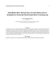
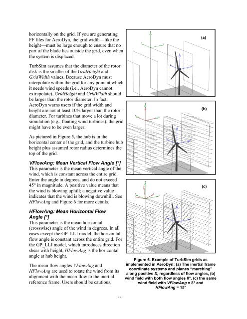
horizontally on the grid. If you are generatingFF files for AeroDyn, the grid width—like theheight—must be large enough to ensure that nopart of the blade lies outside the grid, even whenthe system is displaced.<strong>TurbSim</strong> assumes that the diameter of the rotordisk is the smaller of the GridHeight andGridWidth values. Because AeroDyn mustinterpolate within the grid for any point at whichit needs wind speeds (i.e., AeroDyn cannotextrapolate), GridHeight and GridWidth shouldbe larger than the rotor diameter. In fact,AeroDyn warns users if the grid width andheight are not at least 10% larger than the rotordiameter. For turbines that move a lot duringsimulation (e.g., floating wind turbines), the gridmight have to be even larger.(a)(b)As pictured in Figure 5, the hub is in thehorizontal center of the grid, and the turbine hubheight plus assumed rotor radius determines thetop of the grid.VFlowAng: Mean Vertical Flow Angle [°]This parameter is the mean vertical angle of thewind, which is constant across the entire grid.Enter the angle in degrees, and do not exceed45° in magnitude. A positive value means thatthe wind is blowing uphill; a negative valueindicates that the wind is blowing downhill. SeeHFlowAng and Figure 6 for more details.(c)HFlowAng: Mean Horizontal FlowAngle [°]This parameter is the mean horizontal(crosswise) angle of the wind in degrees. In allcases except the GP_LLJ model, the horizontalflow angle is constant across the entire grid. Forthe GP_LLJ model, which introduces directionshear with height, HFlowAng is the horizontalangle at hub height.The mean flow angles VFlowAng andHFlowAng are used to rotate the wind from itsalignment with the mean flow to the inertialreference frame. Users should be cautious,11Figure 6. Example of <strong>TurbSim</strong> grids asimplemented in AeroDyn: (a) The inertial framecoordinate systems and planes “marching”along positive X, regardless of flow angles, (b)wind field with both flow angles 0°, (c) the samewind field with VFlowAng = 8° andHFlowAng = 15°