The three α variables are coefficients chosen to generate the desired Reynolds stresses for thecorrelated wind components at the hub:PC _ UW = u′ w′hub, correlated hub,correlatedPC _ UV = u′ v′hub, correlated hub,correlatedPC _ VW = v′ w′hub, correlated hub,correlated.(17)Because this method affects the frequency domain somewhat, we have placed the following limiton the coefficients: α ≤ 1. This limit can cause the actual hub Reynolds stresses to differ fromthe desired values.Enter the string “default” for <strong>TurbSim</strong> to compute an appropriate Reynolds stress for PC_UW.PC _ UW =−UStar 2 1−HubHt RefHt The defaultThe default value for the TIDAL model is ( )value for the SMOOTH model is the same as that for the WF_UPW and WF_07D models:2PC _ UW = − UStar . The default value for the WF_14D model has the same magnitude as theSMOOTH model, but is positive 1% of the time (randomly). The magnitudes of the defaults forthe NWTCUP and GP_LLJ models are functions of UStar, RICH_NO, height, mean hub-heightwind speed, and shear across the rotor disk. The signs of the defaults are determined randomly,with the probability that PC_UW is negative increasing with the magnitude of the default. Userscan also enter the string “none” to set αuw= 0 and disable the correlation between the u and wcomponents.PC_UV: Average u′v′ Reynolds Stress at the Hub [m 2 /s 2 ]The PC_UV parameter is the desired average u′v′ Reynolds stress (in m 2 /s 2 ) at the simulated hubpoint. It is used in conjunction with the parameters PC_UW and PC_VW to create crosscomponentcorrelation. See the discussion after parameter PC_UW for details of the correlation.To set αuv= 0 and disable the correlation between the u and v components, enter the string“none.” Users also can enter the string “default” if you would like <strong>TurbSim</strong> to compute a defaultvalue for PC_UV. The magnitudes of the defaults for site-specific models (GP_LLJ, NWTCUP,WF_UPW, WF_07D, and WF_14D) are functions of UStar, RICH_NO, height, mean hub-heightwind speed, and shear across the rotor disk. The signs of the defaults are determined randomly.The default for the SMOOTH and TIDAL models is “none.”PC_VW: Average v′w′ Reynolds Stress at the Hub [m 2 /s 2 ]The PC_VW parameter is the desired average v′w′ Reynolds stress (in m 2 /s 2 ) at the simulated hubpoint. It is used in conjunction with the parameters PC_UW and PC_UV to create crosscomponentcorrelation. See the discussion after parameter PC_UW for details.Users can enter the string “none” to set 0vwα = and disable the correlation between the v and wcomponents. To have <strong>TurbSim</strong> compute a default value for PC_VW, enter the string “default.”The magnitudes of the defaults for site-specific models are functions of UStar, RICH_NO,height, mean hub-height wind speed, and shear across the rotor disk. The signs of the defaults aredetermined randomly. The default for the SMOOTH and TIDAL models is “none.”20
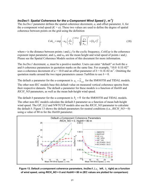
IncDec1: Spatial Coherence for the u-Component Wind Speed [-, m -1 ]The IncDec1 parameter defines the spatial coherence decrement, a, and offset parameter, b, forthe u-component wind speed (K = u). These two values are used to define the degree of spatialcoherence between points on the grid using the definition⎛CohExp2⎛i, jexp r ⎞ ⎛ fr⎞Coh =⎜− aK + bKr⎜ z ⎟⎜m u ⎟⎜ ⎝ ⎠ ⎝ m ⎠⎝( )2⎞⎟, (18)⎟⎠where r is the distance between points i and j, f is the cyclic frequency, CohExp is the coherenceexponent input parameter, and z m and u m are the mean height and wind speed of points i and j.Please see the Spatial Coherence Models section of this document for more information.The IncDec1 decrement, a, must be a positive number. Users can enter “default” or both the aand b coherence parameters in quotation marks on the same line. For example, “10.0 0.1E-02”uses a coherence decrement of a = 10.0 and an offset parameter of b = 0.1E-02 m -1 . Omitting thequotation marks around the two input parameters causes <strong>TurbSim</strong> to use b = 0.The default a parameter for the u-component is au= u for the SMOOTH and TIDAL models.hubThe other non-IEC models base this default value on measured vertical coherence spectra fromtheir respective datasets. The default a parameter for these models is a function of HubHt andRICH_NO parameters, as well as the mean hub-height wind speed.The default b parameter for the u-component is 0ub = for the SMOOTH and TIDAL models.The other non-IEC models calculate the default b parameter as a function of mean hub-heightwind speed. The GP_LLJ and NWTCUP models also use the RICH_NO parameter to calculatethe default b. Figure 13 shows the default parameters for neutral conditions (i.e., RICH_NO = 0)using a value of 80 m for the HubHt parameter.Figure 13. Default u-component coherence parameters, IncDec1, ( a left,ub right) as a functionuof wind speed, using RICH_NO = 0 and HubHt = 80 m (IEC values are plotted for comparison)21
- Page 4 and 5: AcknowledgementsTurbSim was written
- Page 6 and 7: Table of ContentsAcknowledgements .
- Page 8 and 9: List of FiguresFigure 1. TurbSim si
- Page 10 and 11: Figure G-6. Unstable velocity spect
- Page 12 and 13: Buhl added the ability to generate
- Page 14 and 15: “CertTest.bat” and set the envi
- Page 16 and 17: TurbSim assumes that parameters are
- Page 18 and 19: parameter RICH_NO) is greater than
- Page 20 and 21: UsableTime: Usable Time Series Leng
- Page 22 and 23: however, because AeroDyn—in its i
- Page 24 and 25: Figure 8. Coherent turbulent kineti
- Page 26 and 27: Figure 9. Default jet wind speed fo
- Page 28 and 29: ⎛1000⎞θ = T ⎜ ⎟⎝ p ⎠0.
- Page 32 and 33: IncDec2: Spatial Coherence for the
- Page 34 and 35: Table 8. Valid CTEventFile EntriesI
- Page 36 and 37: files a “.bin” extension. At ea
- Page 38 and 39: generated for the FF Bladed-style
- Page 40 and 41: Spectral ModelsTurbSim uses a modif
- Page 42 and 43: K( )S f = UStar2s1, K⎛ z ⎞⎛φ
- Page 44 and 45: NWTCUP: The NREL National Wind Tech
- Page 46 and 47: Figure 20. GPLLJ-model stable/neutr
- Page 48 and 49: (NumPeaks K = 2, K = u, v, w) and e
- Page 50 and 51: Cohi,j( f )iiSij( f )( ) ( )= , (49
- Page 52 and 53: where u( z ) is the mean wind speed
- Page 54 and 55: atmosphere. To obtain more events w
- Page 56 and 57: See Appendix H in this document for
- Page 58 and 59: • The statistics calculated in th
- Page 60 and 61: References[1] Laino, D. J.; Hansen,
- Page 62 and 63: [28] Olesen, H.R.; Larsen, S.E.; H
- Page 64 and 65: Appendix B: TurbSim Quick-Start Gui
- Page 66 and 67: Appendix C: Flow ChartsTurbSim Inpu
- Page 68 and 69: TurbSim InputFileTurbine/Model Spec
- Page 70 and 71: TurbSim InputFileMeteorologicalBoun
- Page 72 and 73: TurbSim Input FileDefault Input Val
- Page 74 and 75: Appendix D: Full-Field TurbSim Bina
- Page 76 and 77: Appendix E: Full-Field Bladed-Style
- Page 78 and 79: Appendix F: Tower Data Binary File
- Page 80 and 81:
Appendix G: Velocity Spectra Compar
- Page 82 and 83:
Default UStar (m/s)SMOOTH 0.644NWTC
- Page 84 and 85:
Default UStar (m/s)SMOOTH 0.656NWTC
- Page 86 and 87:
Appendix H: Sample AeroDyn Coherent