TurbSim User's Guide: Version 1.06.00 - NREL
TurbSim User's Guide: Version 1.06.00 - NREL
TurbSim User's Guide: Version 1.06.00 - NREL

You also want an ePaper? Increase the reach of your titles
YUMPU automatically turns print PDFs into web optimized ePapers that Google loves.
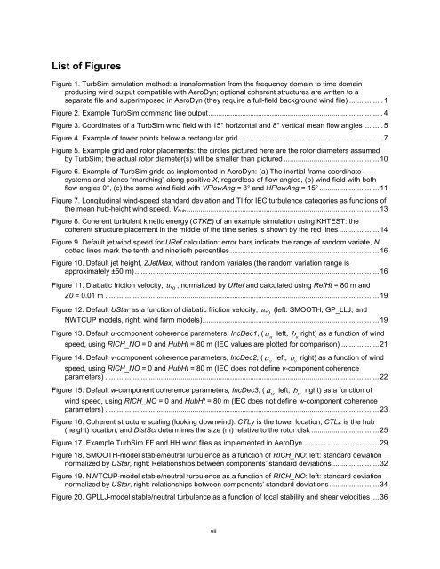
List of FiguresFigure 1. <strong>TurbSim</strong> simulation method: a transformation from the frequency domain to time domainproducing wind output compatible with AeroDyn; optional coherent structures are written to aseparate file and superimposed in AeroDyn (they require a full-field background wind file) ................. 1Figure 2. Example <strong>TurbSim</strong> command line output ........................................................................................ 4Figure 3. Coordinates of a <strong>TurbSim</strong> wind field with 15° horizontal and 8° vertical mean flow angles .......... 5Figure 4. Example of tower points below a rectangular grid ......................................................................... 7Figure 5. Example grid and rotor placements: the circles pictured here are the rotor diameters assumedby <strong>TurbSim</strong>; the actual rotor diameter(s) will be smaller than pictured ................................................ 10Figure 6. Example of <strong>TurbSim</strong> grids as implemented in AeroDyn: (a) The inertial frame coordinatesystems and planes “marching” along positive X, regardless of flow angles, (b) wind field with bothflow angles 0°, (c) the same wind field with VFlowAng = 8° and HFlowAng = 15° .............................. 11Figure 7. Longitudinal wind-speed standard deviation and TI for IEC turbulence categories as functions ofthe mean hub-height wind speed, V hub ................................................................................................. 13Figure 8. Coherent turbulent kinetic energy (CTKE) of an example simulation using KHTEST: thecoherent structure placement in the middle of the time series is shown by the red lines .................... 14Figure 9. Default jet wind speed for URef calculation: error bars indicate the range of random variate, N;dotted lines mark the tenth and ninetieth percentiles ........................................................................... 16Figure 10. Default jet height, ZJetMax, without random variates (the random variation range isapproximately ±50 m) ........................................................................................................................... 16Figure 11. Diabatic friction velocity, u*0, normalized by URef and calculated using RefHt = 80 m andZ0 = 0.01 m .......................................................................................................................................... 19Figure 12. Default UStar as a function of diabatic friction velocity, u*0(left: SMOOTH, GP_LLJ, andNWTCUP models, right: wind farm models) ......................................................................................... 19Figure 13. Default u-component coherence parameters, IncDec1, ( a left,ub right) as a function of winduspeed, using RICH_NO = 0 and HubHt = 80 m (IEC values are plotted for comparison) ................... 21Figure 14. Default v-component coherence parameters, IncDec2, ( a left,vb right) as a function of windvspeed, using RICH_NO = 0 and HubHt = 80 m (IEC does not define v-component coherenceparameters) .......................................................................................................................................... 22Figure 15. Default w-component coherence parameters, IncDec3, ( a left,wb right) as a function ofwwind speed, using RICH_NO = 0 and HubHt = 80 m (IEC does not define w-component coherenceparameters) .......................................................................................................................................... 23Figure 16. Coherent structure scaling (looking downwind): CTLy is the tower location, CTLz is the hub(height) location, and DistScl determines the size (m) relative to the rotor disk .................................. 25Figure 17. Example <strong>TurbSim</strong> FF and HH wind files as implemented in AeroDyn. ..................................... 29Figure 18. SMOOTH-model stable/neutral turbulence as a function of RICH_NO: left: standard deviationnormalized by UStar, right: Relationships between components’ standard deviations ........................ 32Figure 19. NWTCUP-model stable/neutral turbulence as a function of RICH_NO: left: standard deviationnormalized by UStar, right: relationships between components’ standard deviations ......................... 34Figure 20. GPLLJ-model stable/neutral turbulence as a function of local stability and shear velocities .... 36vii