TurbSim User's Guide: Version 1.06.00 - NREL
TurbSim User's Guide: Version 1.06.00 - NREL
TurbSim User's Guide: Version 1.06.00 - NREL

You also want an ePaper? Increase the reach of your titles
YUMPU automatically turns print PDFs into web optimized ePapers that Google loves.
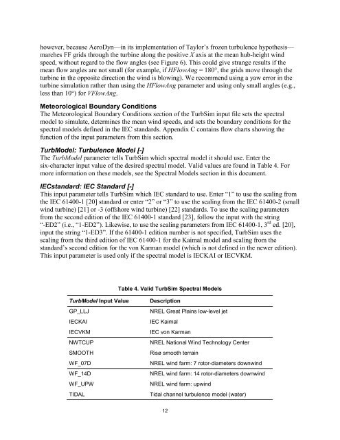
however, because AeroDyn—in its implementation of Taylor’s frozen turbulence hypothesis—marches FF grids through the turbine along the positive X axis at the mean hub-height windspeed, without regard to the flow angles (see Figure 6). This could give strange results if themean flow angles are not small (for example, if HFlowAng = 180°, the grids move through theturbine in the opposite direction the wind is blowing). We recommend using a yaw error in theturbine simulation rather than using the HFlowAng parameter and using only small angles (e.g.,less than 10°) for VFlowAng.Meteorological Boundary ConditionsThe Meteorological Boundary Conditions section of the <strong>TurbSim</strong> input file sets the spectralmodel to simulate, determines the mean wind speeds, and sets the boundary conditions for thespectral models defined in the IEC standards. Appendix C contains flow charts showing thefunction of the input parameters from this section.TurbModel: Turbulence Model [-]The TurbModel parameter tells <strong>TurbSim</strong> which spectral model it should use. Enter thesix-character input value of the desired spectral model. Valid values are found in Table 4. Formore information on these models, see the Spectral Models section in this document.IECstandard: IEC Standard [-]This input parameter tells <strong>TurbSim</strong> which IEC standard to use. Enter “1” to use the scaling fromthe IEC 61400-1 [20] standard or enter “2” or “3” to use the scaling from the IEC 61400-2 (smallwind turbine) [21] or -3 (offshore wind turbine) [22] standards. To use the scaling parametersfrom the second edition of the IEC 61400-1 standard [23], follow the input with the string“-ED2” (i.e., “1-ED2”). Likewise, to use the scaling parameters from IEC 61400-1, 3 rd ed. [20],input the string “1-ED3”. If the 61400-1 edition number is not specified, <strong>TurbSim</strong> uses thescaling from the third edition of IEC 61400-1 for the Kaimal model and scaling from thestandard’s second edition for the von Karman model (which is not defined in the newer edition).This input parameter is used only if the spectral model is IECKAI or IECVKM.Table 4. Valid <strong>TurbSim</strong> Spectral ModelsTurbModel Input ValueGP_LLJIECKAIIECVKMNWTCUPSMOOTHWF_07DWF_14DWF_UPWTIDALDescription<strong>NREL</strong> Great Plains low-level jetIEC KaimalIEC von Karman<strong>NREL</strong> National Wind Technology CenterRisø smooth terrain<strong>NREL</strong> wind farm: 7 rotor-diameters downwind<strong>NREL</strong> wind farm: 14 rotor-diameters downwind<strong>NREL</strong> wind farm: upwindTidal channel turbulence model (water)12