TurbSim User's Guide: Version 1.06.00 - NREL
TurbSim User's Guide: Version 1.06.00 - NREL
TurbSim User's Guide: Version 1.06.00 - NREL

You also want an ePaper? Increase the reach of your titles
YUMPU automatically turns print PDFs into web optimized ePapers that Google loves.
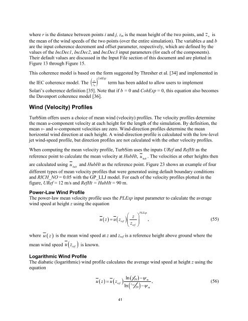
where r is the distance between points i and j, z m is the mean height of the two points, and u m isthe mean of the wind speeds of the two points (over the entire simulation). The variables a and bare the input coherence decrement and offset parameter, respectively, which are defined by thevalues of the IncDec1, IncDec2, and IncDec3 input parameters (for each of the components).Their default values are discussed in the Input File section of this document and are plotted inFigure 13 through Figure 15.This coherence model is based on the form suggested by Thresher et al. [34] and implemented inrthe IEC coherence model. The ( )mCohExpz term has been added to allow users to implementSolari’s coherence definition [35]. Note that if b = 0 and CohExp = 0, this equation also becomesthe Davenport coherence model [36].Wind (Velocity) Profiles<strong>TurbSim</strong> offers users a choice of mean wind (velocity) profiles. The velocity profiles determinethe mean u-component velocity at each height for the length of the simulation. By definition, themean v- and w-component velocities are zero. Wind-direction profiles determine the meanhorizontal wind direction at each height. A wind-direction profile is calculated with the low-leveljet wind-speed profile, but direction profiles are not calculated with the other velocity profiles.When computing the mean velocity profile, <strong>TurbSim</strong> uses the inputs URef and RefHt as thereference point to calculate the mean velocity at HubHt, u . The velocities at other heights thenhubare calculated using u and HubHt as the reference point. Figure 23 shows an example of fourhubdifferent types of mean velocity profiles that were generated using default boundary conditionsand RICH_NO = 0.05 with the GP_LLJ model. For each of the velocity profiles plotted in thefigure, URef = 12 m/s and RefHt = HubHt = 90 m.Power-Law Wind ProfileThe power-law mean velocity profile uses the PLExp input parameter to calculate the averagewind speed at height z using the equation⎛ z ⎞= ⎜z ⎟⎝ ref ⎠( ) u( zref)u zPLExp, (55)where u( z ) is the mean wind speed at z and z ref is a reference height above ground where themean wind speed u( zref ) is known.Logarithmic Wind ProfileThe diabatic (logarithmic) wind profile calculates the average wind speed at height z using theequation( ) = u( zref)u zlnlnz( Z0 )z( )refZ0−ψm, (56)−ψm41