

User Instructions SITOP DC UPS Software “Application”
User Instructions SITOP DC UPS Software “Application”
User Instructions SITOP DC UPS Software “Application”

Create successful ePaper yourself
Turn your PDF publications into a flip-book with our unique Google optimized e-Paper software.
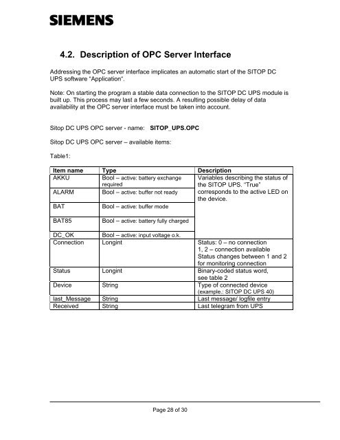
4.2. Description of OPC Server Interface<br />
Addressing the OPC server interface implicates an automatic start of the <strong>SITOP</strong> <strong>DC</strong><br />
<strong>UPS</strong> software “Application“.<br />
Note: On starting the program a stable data connection to the <strong>SITOP</strong> <strong>DC</strong> <strong>UPS</strong> module is<br />
built up. This process may last a few seconds. A resulting possible delay of data<br />
availability at the OPC server interface must be taken into account.<br />
Sitop <strong>DC</strong> <strong>UPS</strong> OPC server - name: <strong>SITOP</strong>_<strong>UPS</strong>.OPC<br />
Sitop <strong>DC</strong> <strong>UPS</strong> OPC server – available items:<br />
Table1:<br />
Item name Type Description<br />
AKKU<br />
Bool – active: battery exchange Variables describing the status of<br />
required<br />
the <strong>SITOP</strong> <strong>UPS</strong>. “True”<br />
ALARM Bool – active: buffer not ready corresponds to the active LED on<br />
the device.<br />
BAT<br />
Bool – active: buffer mode<br />
BAT85<br />
Bool – active: battery fully charged<br />
<strong>DC</strong>_OK Bool – active: input voltage o.k.<br />
Connection Longint Status: 0 – no connection<br />
1, 2 – connection available<br />
Status changes between 1 and 2<br />
for monitoring connection<br />
Status Longint Binary-coded status word,<br />
see table 2<br />
Device String Type of connected device<br />
(example.: <strong>SITOP</strong> <strong>DC</strong> <strong>UPS</strong> 40)<br />
last_Message String Last message/ logfile entry<br />
Received String Last telegram from <strong>UPS</strong><br />
Page 28 of 30


