Offshore Electricity Infrastructure in Europe - European Wind Energy ...
Offshore Electricity Infrastructure in Europe - European Wind Energy ...
Offshore Electricity Infrastructure in Europe - European Wind Energy ...

Create successful ePaper yourself
Turn your PDF publications into a flip-book with our unique Google optimized e-Paper software.
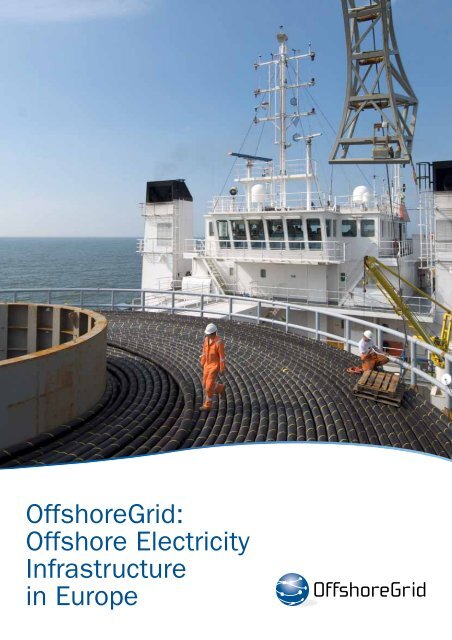
<strong>Offshore</strong>Grid:<br />
<strong>Offshore</strong> <strong>Electricity</strong><br />
<strong>Infrastructure</strong><br />
<strong>in</strong> <strong>Europe</strong>
<strong>Offshore</strong> <strong>Electricity</strong><br />
Grid <strong>Infrastructure</strong><br />
<strong>in</strong> <strong>Europe</strong><br />
A Techno-Economic Assessment<br />
3E (coord<strong>in</strong>ator),<br />
dena, EWEA, ForW<strong>in</strong>d, IEO,<br />
NTUA, Senergy, SINTEF<br />
F<strong>in</strong>al Report, October 2011
PRINcIPAl AUThORS:<br />
Jan De Decker, Paul Kreutzkamp (3E, coord<strong>in</strong>ator)<br />
AUThORS:<br />
3E (coord<strong>in</strong>ator): Jan De Decker, Paul Kreutzkamp, Pieter Joseph, Achim Woyte<br />
Senergy Econnect: Simon Cowdroy, Peter McGarley<br />
SINTEF: Leif Warland, Harald Svendsen<br />
dena: Jakob Völker, Carol<strong>in</strong> Funk, Hannes Pe<strong>in</strong>l<br />
ForW<strong>in</strong>d:Jens Tambke, Lüder von Bremen<br />
IEO: Katarzyna Michalowska<br />
NTUA: George Caralis<br />
MAIN REvIEWERS:<br />
3E (coord<strong>in</strong>ator): Jan De Decker, Paul Kreutzkamp, Natalie Picot<br />
dena: Jakob Völker<br />
EWEA: Sharon Wokke, Christian Kjaer, Jacopo Moccia, Frans Van Hulle, Paul Wilczek, Just<strong>in</strong> Wilkes<br />
EdITING:<br />
EWEA: Sarah Azau, Zoë Casey, Tom Rowe<br />
AckNOWlEdGEMENTS:<br />
Wilfried Breuer (Siemens), Paul Carter (SLP Eng<strong>in</strong>eer<strong>in</strong>g), Manuela Conconi (EWEA), Frederik Deloof (Secretariat Benelux),<br />
Frédéric Dunon (Elia), Dana Dutianu (EC), Rafael E. Bonchang (Alstom Grid), Claire Grandadam (3E), Jan Hensmans (FOD<br />
Economie), Andrea Hercsuth (EC), Matthias Kirchner (Nexans), Niels Ladefoged (EC), Nico Nolte (BSH), Antje Orths (Energ<strong>in</strong>et.<br />
dk), Glória Rodrigues (EWEA), Fabian Scharf (BNetzA), Christophe Schramm (EC), Alberto Schultze (Siemens), Ravi Srikandam<br />
(arepo consult), Guenter Stark (ABB), G<strong>in</strong>a Van Dijk (Tennet), Heleen Van Hoof (VREG), Jan van den Berg (Tennet), Teun Van<br />
Biert (Tennet), Kar<strong>in</strong>a Veum (ECN), Bo Westman (ABB)<br />
design: www.mardi.be;<br />
Pr<strong>in</strong>t: www.artoos.be;<br />
Production coord<strong>in</strong>ation: Raffaella Bianch<strong>in</strong>, Crist<strong>in</strong>a Rubio (EWEA);<br />
cover photo: Detlev Gehr<strong>in</strong>g/ Stiftung <strong>Offshore</strong> W<strong>in</strong>denergie<br />
Agreement n.: EIE/08/780/SI2.528573<br />
Duration: May 2009 – October 2011<br />
Co-ord<strong>in</strong>ator: 3E<br />
The sole responsibility for the content of this publication lies with the authors. It does not necessarily<br />
reflect the op<strong>in</strong>ion of the <strong>Europe</strong>an Union.<br />
Neither the EACI nor the <strong>Europe</strong>an Commission are responsible for any use that may be made of<br />
the <strong>in</strong>formation conta<strong>in</strong>ed <strong>in</strong> this publication.<br />
2 <strong>Offshore</strong>Grid – F<strong>in</strong>al Report
COORDINATOR<br />
PROjeCT PARTNeRs:<br />
The Deutsche Energie-Agentur<br />
GmbH (dena) - the German<br />
<strong>Energy</strong> Agency - is the centre of<br />
expertise for energy efficiency,<br />
renewable energy sources and<br />
<strong>in</strong>telligent energy systems.<br />
www.dena.de<br />
IEO: Institute for Renewable<br />
<strong>Energy</strong> is a Polish <strong>in</strong>dependent<br />
consultancy company and a<br />
th<strong>in</strong>k tank, l<strong>in</strong>k<strong>in</strong>g research,<br />
technology and policy<br />
development activities <strong>in</strong> the<br />
area of renewable energy.<br />
www.ieo.pl<br />
Supported by<br />
<strong>Offshore</strong>Grid – F<strong>in</strong>al Report<br />
3E is a global, <strong>in</strong>dependent<br />
renewable energy consultancy,<br />
provid<strong>in</strong>g full-scope technical<br />
and strategic guidance <strong>in</strong> w<strong>in</strong>d<br />
(on & offshore), solar, grids and<br />
power markets.<br />
www.3e.eu<br />
The <strong>Europe</strong>an W<strong>in</strong>d <strong>Energy</strong><br />
Association (EWEA) is the<br />
voice of the w<strong>in</strong>d <strong>in</strong>dustry,<br />
actively promot<strong>in</strong>g the<br />
utilisation of w<strong>in</strong>d power <strong>in</strong><br />
<strong>Europe</strong> and worldwide.<br />
www.ewea.org<br />
NTUA-RENES: The Renewable<br />
<strong>Energy</strong> Sources unit is an<br />
educational and research unit <strong>in</strong><br />
the National Technical University<br />
of Athens dedicated to the<br />
promotion of renewable energy<br />
sources.<br />
www.ntua.gr<br />
SINTEF <strong>Energy</strong> Research is a<br />
Norwegian research <strong>in</strong>stitute that<br />
develops solutions for electricity<br />
generation and transformation,<br />
distribution and end-use of energy,<br />
onshore and offshore/subsea.<br />
www.s<strong>in</strong>tef.no<br />
ForW<strong>in</strong>d, the jo<strong>in</strong>t centre for<br />
w<strong>in</strong>d energy research of the<br />
universities of Oldenburg,<br />
Hannover and Bremen is one<br />
of <strong>Europe</strong>’s lead<strong>in</strong>g academic<br />
<strong>in</strong>stitutions for all aspects<br />
of w<strong>in</strong>d energy, from turb<strong>in</strong>e<br />
design to large-scale w<strong>in</strong>d flow<br />
simulations.<br />
www.forw<strong>in</strong>d.de<br />
Senergy Econnect specialise<br />
<strong>in</strong> the electrical connection<br />
of renewable energy projects<br />
to grid networks; from <strong>in</strong>itial<br />
concept, to design and<br />
commission<strong>in</strong>g worldwide.<br />
www.senergyworld.com<br />
3
Table of contents<br />
FOREWORd 6<br />
EXEcUTIvE SUMMARY 7<br />
1 INTROdUcTION 17<br />
1.1 Context and background 18<br />
1.2 Objective of <strong>Offshore</strong>Grid 19<br />
1.3 Methodology and approach 19<br />
1.4 Stakeholders 19<br />
1.5 Document structure 20<br />
2 kEY ASSUMPTIONS ANd ScENARIOS 21<br />
2.1 <strong>Offshore</strong> w<strong>in</strong>d development scenarios <strong>in</strong> Northern <strong>Europe</strong> 22<br />
2.2 Generation capacity and commodity price scenarios 23<br />
2.3 Technology to connect offshore w<strong>in</strong>d energy 25<br />
3 METhOdOlOGY - SIMUlATION INPUTS ANd MOdElS 27<br />
3.1 W<strong>in</strong>d power series model 28<br />
3.2 Power market and power flow model 29<br />
3.3 <strong>Infrastructure</strong> cost model 29<br />
3.4 Case-<strong>in</strong>dependent model 30<br />
4 RESUlTS 31<br />
4.1 W<strong>in</strong>d output statistics 32<br />
4.1.1 Spatial smooth<strong>in</strong>g of w<strong>in</strong>d power 32<br />
4.1.2 Spatial power correlations 33<br />
4.2 W<strong>in</strong>d farm hubs versus <strong>in</strong>dividual connections 35<br />
4.2.1 Hubs and <strong>in</strong>dividual connections <strong>in</strong> the sea bas<strong>in</strong>s <strong>in</strong> Northern <strong>Europe</strong> 36<br />
4.2.2 Overall cost reductions expected from shared connections via hubs 39<br />
4.2.3 Scheduled w<strong>in</strong>d farm connection – risk of stranded hub <strong>in</strong>vestments 40<br />
4.2.4 Conclusion and Discussion on Hubs versus Individual Connections 42<br />
4.3 Integrated design – case studies 42<br />
4.3.1 Tee-<strong>in</strong> solutions – Case study evaluation 43<br />
4.3.2 Hub-to-hub solutions – Case study evaluation 46<br />
4.4 Integrated design – case-<strong>in</strong>dependent model 49<br />
4.4.1 M<strong>in</strong>imum distance for tee-<strong>in</strong> solution 49<br />
4.4.2 Maximum distance between hubs for <strong>in</strong>tegrated hub solution 52<br />
4.4.3 The Cobra cable case study 55<br />
4.4.4 Conclusion on <strong>in</strong>tegrated design 57<br />
4.5 Overall grid design 58<br />
4.5.1 Approach 58<br />
4.5.2 The Direct Design methodology 59<br />
4.5.3 The Split Design methodology 64<br />
4.5.4 Comparison of methodologies 69<br />
4.5.5 <strong>Infrastructure</strong> <strong>in</strong>vestment – circuit length and total costs 74<br />
4.5.6 Power system impact of the offshore grid 77<br />
4.5.7 Conclusion and discussion 78<br />
4 <strong>Offshore</strong>Grid – F<strong>in</strong>al Report
5 TOWARdS AN OFFShORE GRId – FURThER cONSIdERATIONS 81<br />
5.1 Challenges and barriers 82<br />
5.1.1 Operation and ma<strong>in</strong>tenance of an offshore grid and further technical challenges 82<br />
5.1.2 Regulatory framework and policy 84<br />
5.1.3 Market challenges and f<strong>in</strong>anc<strong>in</strong>g 86<br />
5.1.4 Supply cha<strong>in</strong> 86<br />
5.2 Ongo<strong>in</strong>g policy and <strong>in</strong>dustry <strong>in</strong>itiatives 87<br />
6 cONclUSIONS ANd REcOMMENdATIONS 89<br />
6.1 W<strong>in</strong>d farm hubs 90<br />
6.2 Tee-<strong>in</strong> solutions 91<br />
6.3 Hub-to-hub solutions 92<br />
6.4 Overall grid design 94<br />
6.5 Overall recommendations 96<br />
7 AckNOWlEdGEMENTS ANd FUNdING 99<br />
8 REFERENcES 101<br />
<strong>Offshore</strong>Grid – F<strong>in</strong>al Report<br />
5
FOREWORD<br />
The <strong>Offshore</strong>Grid project is the first <strong>in</strong>-depth analysis of how to build a cost-efficient<br />
grid <strong>in</strong> the North and Baltic Seas. As such, it is a compell<strong>in</strong>g milestone <strong>in</strong> the<br />
development of a secure, <strong>in</strong>terconnected <strong>Europe</strong>an power system, able to <strong>in</strong>tegrate<br />
<strong>in</strong>creas<strong>in</strong>g amounts of renewable energy.<br />
The need for cleaner and safer energy supplies to counter climate change is clear.<br />
Renewable power is key to achiev<strong>in</strong>g <strong>Europe</strong>’s 20-20-20 targets and to cope with energy<br />
related challenges far beyond 2020. <strong>Offshore</strong> w<strong>in</strong>d, <strong>in</strong> particular, has tremendous<br />
potential. It could generate more than 500 TWh per year by 2030, enough electricity<br />
to meet 15% of <strong>Europe</strong>’s yearly electricity consumption.<br />
However, reach<strong>in</strong>g these goals and mov<strong>in</strong>g towards an efficient, <strong>in</strong>tegrated <strong>Europe</strong>an electricity market will not<br />
be possible without a reliable, modernised and efficient grid, both onshore and offshore. Onshore, this means<br />
significant <strong>in</strong>vestments to strengthen current <strong>in</strong>frastructure, which faces strong public opposition and lengthy<br />
project lead times. <strong>Offshore</strong>, the challenge is to more efficiently connect power harvested at sea with the<br />
onshore transmission system, while at the same time build<strong>in</strong>g a system which can actively contribute to stability<br />
and security of supply by enabl<strong>in</strong>g further <strong>in</strong>tegration of the <strong>Europe</strong>an power market. A coherent <strong>Europe</strong>an<br />
long-term vision for both the onshore and offshore electricity grid is a prerequisite to make the required steps <strong>in</strong><br />
an optimal way.<br />
The <strong>Offshore</strong>Grid project results are a practical bluepr<strong>in</strong>t for policymakers, developers and transmission grid<br />
operators, to plan and design a meshed offshore grid. They provide explicit guidance for <strong>in</strong>dividual projects while<br />
not los<strong>in</strong>g sight of the overall grid design. The analysis of costs and benefits of different configurations addressed<br />
<strong>in</strong> this study will help policy makers and regulators anticipate developments and provide <strong>in</strong>centives that trigger<br />
the necessary <strong>in</strong>vestments at the right time and avoid stranded <strong>in</strong>vestments.<br />
Tak<strong>in</strong>g the <strong>Offshore</strong>Grid results as basis for discussion, a concrete roadmap for a grid at sea can be developed<br />
<strong>in</strong>volv<strong>in</strong>g all stakeholders. With today’s fast developments <strong>in</strong> the offshore w<strong>in</strong>d <strong>in</strong>dustry, now is our opportunity.<br />
Geert Palmers,<br />
CEO, 3E<br />
6 <strong>Offshore</strong>Grid – F<strong>in</strong>al Report
ExEcuTivE SuMMAry<br />
• The <strong>Offshore</strong>Grid project<br />
• Ma<strong>in</strong> results <strong>in</strong> a nutshell<br />
• Analysis of different connection concepts<br />
• General recommendations<br />
Photo: Vestas
Executive Summary<br />
I. The <strong>Offshore</strong>Grid project<br />
<strong>Offshore</strong>Grid is a techno-economic study funded by the<br />
EU’s Intelligent <strong>Energy</strong> <strong>Europe</strong> (IEE) programme. It has<br />
developed a scientific view on an offshore grid <strong>in</strong> northern<br />
<strong>Europe</strong> along with a suitable regulatory framework<br />
that takes technical, economic, policy and regulatory<br />
aspects <strong>in</strong>to account. This document is the f<strong>in</strong>al report<br />
of the project. It summarises the key assumptions,<br />
the methodology and the results, draws conclusions<br />
from the work and provides recommendations.<br />
The benefits of an offshore grid<br />
The exploitation of <strong>Europe</strong>’s offshore w<strong>in</strong>d potential<br />
br<strong>in</strong>gs new challenges and opportunities for power<br />
transmission <strong>in</strong> <strong>Europe</strong>. <strong>Offshore</strong> w<strong>in</strong>d capacity<br />
<strong>in</strong> <strong>Europe</strong> is expected to reach 150 GW <strong>in</strong> 2030 1 .<br />
The majority of the sites currently be<strong>in</strong>g considered<br />
for offshore w<strong>in</strong>d projects are situated close to the<br />
<strong>Europe</strong>an coast, not further than 100 km from shore.<br />
This is <strong>in</strong> part due to the high cost of grid connection,<br />
limited grid availability and the absence of a proper<br />
regulatory framework for w<strong>in</strong>d farms that could feed<br />
several countries at once. Look<strong>in</strong>g at the North Sea<br />
alone, with its potential for several hundreds of<br />
Gigawatts of w<strong>in</strong>d power, an offshore grid connect<strong>in</strong>g<br />
different Member States would enable this w<strong>in</strong>d<br />
power to be transported to the load centres and at<br />
the same time facilitate competition and electricity<br />
trade between countries. A draft work<strong>in</strong>g plan for<br />
an <strong>in</strong>ter-governmental <strong>in</strong>itiative known as the North<br />
Seas Countries’ <strong>Offshore</strong> Grid Initiative (NSCOGI)<br />
summarises the advantages of such a grid 2 :<br />
• Security of supply<br />
– Improve the connection between big load centres<br />
around the North Sea.<br />
– Reduce dependency on gas and oil from unstable<br />
regions.<br />
– Transmit <strong>in</strong>digenous offshore renewable electricity<br />
to where it can be used onshore.<br />
– Bypass onshore electricity transmission<br />
bottlenecks.<br />
• competition and market<br />
– Development of more <strong>in</strong>terconnection between<br />
countries and power systems enhances trade<br />
and improves competition on the <strong>Europe</strong>an energy<br />
market.<br />
– Increased possibilities for arbitrage and limitation<br />
of price spikes.<br />
• Integration of renewable energy<br />
– Facilitation of large scale offshore w<strong>in</strong>d power<br />
plants and other mar<strong>in</strong>e technologies.<br />
– Enabl<strong>in</strong>g the spatial smooth<strong>in</strong>g effects of w<strong>in</strong>d<br />
and other renewable power, thus reduc<strong>in</strong>g variability<br />
and the result<strong>in</strong>g need for flexibility.<br />
– Connection to large hydropower capacity <strong>in</strong><br />
Scand<strong>in</strong>avia, <strong>in</strong>troduc<strong>in</strong>g flexibility <strong>in</strong>to the power<br />
sys tem to compensate for variability from w<strong>in</strong>d<br />
and other renewable energy sources.<br />
– Contribution to <strong>Europe</strong>’s 2020 targets for renewables<br />
and CO 2 emission reductions.<br />
II. Ma<strong>in</strong> results <strong>in</strong> a nutshell<br />
The <strong>Offshore</strong>Grid study confirms these advantages<br />
after hav<strong>in</strong>g <strong>in</strong>vestigated both the technical and economic<br />
questions.<br />
The first step was to study the connection of the offshore<br />
w<strong>in</strong>d farms to shore, without look<strong>in</strong>g <strong>in</strong>to the<br />
details of an <strong>in</strong>terconnected solution yet. In this regard<br />
<strong>Offshore</strong>Grid comes to the conclusion that us<strong>in</strong>g<br />
hub connections for offshore w<strong>in</strong>d farms – that is,<br />
connect<strong>in</strong>g up w<strong>in</strong>d farms that are close to one another,<br />
form<strong>in</strong>g only one transmission l<strong>in</strong>e to shore - is<br />
often highly beneficial. <strong>Offshore</strong>Grid assessed 321<br />
offshore w<strong>in</strong>d farm projects, and recommends that<br />
114 of these 321 be clustered <strong>in</strong> hubs. If this were<br />
done, <strong>Offshore</strong>Grid has calculated that €14 bn could<br />
be saved up to 2030 compared to connect<strong>in</strong>g each<br />
of the 321 w<strong>in</strong>d farms <strong>in</strong>dividually to shore – that is,<br />
<strong>in</strong>vestments would be €69 bn as opposed to €83 bn.<br />
1 EWEA, Pure Power – W<strong>in</strong>d energy targets for 2020 and 2030, 2011 update, July 2011.<br />
2 Draft Work<strong>in</strong>g Plan Proposal for <strong>Offshore</strong> <strong>Electricity</strong> <strong>Infrastructure</strong>, 3E for Belgian M<strong>in</strong>istry of <strong>Energy</strong>, Unpublished, 2010.<br />
8 <strong>Offshore</strong>Grid – F<strong>in</strong>al Report
Based on this connection scenario (called the “hub<br />
base case sce nario”) <strong>in</strong> a second step two highly costefficient<br />
<strong>in</strong>terconnected grid designs were then drawn<br />
up - the “Direct Design” and “Split Design”.<br />
In the Direct Design, <strong>in</strong>terconnectors are built to promote<br />
unconstra<strong>in</strong>ed trade between countries and<br />
electricity markets as average price difference levels<br />
are high. Once additional direct <strong>in</strong>terconnectors become<br />
non-beneficial, tee-<strong>in</strong>, hub-to-hub and meshed<br />
grid concepts are added to arrive at an overall grid<br />
design (for an explanation of these terms, see Section<br />
III of the Executive Summary).<br />
The Split Design is essentially design<strong>in</strong>g an offshore<br />
grid around the planned offshore w<strong>in</strong>d farms. Thus,<br />
as a start<strong>in</strong>g po<strong>in</strong>t not only direct <strong>in</strong>terconnectors are<br />
<strong>in</strong>vestigated but also <strong>in</strong>terconnections are built by<br />
splitt<strong>in</strong>g the con nection of some of the larger offshore<br />
w<strong>in</strong>d farms between countries. These “split w<strong>in</strong>d farm<br />
connections” establish a path for (constra<strong>in</strong>ed) trade.<br />
These offshore w<strong>in</strong>d farm nodes are then - as <strong>in</strong> the<br />
Direct Design - further <strong>in</strong>terconnected to establish an<br />
overall ‘meshed’ design where beneficial.<br />
The overall <strong>in</strong>vestment costs are €86 bn for the Direct<br />
Design and €84 bn for the Split Design. This <strong>in</strong>cludes<br />
€69 bn of <strong>in</strong>vestment costs for the most efficient connection<br />
(hub-connections where beneficial as <strong>in</strong> the<br />
FIGURE 1.1: TOTAl INvESTMENTS FOR ThE OvERAll GRId dESIGN<br />
<strong>Infrastructure</strong><br />
cost (€bn)<br />
100<br />
Reference and base case<br />
90<br />
92<br />
80<br />
83<br />
78<br />
70<br />
60<br />
50<br />
40<br />
30<br />
20<br />
10<br />
69<br />
0<br />
Radial Base case Hub Base case<br />
<strong>Offshore</strong>Grid – F<strong>in</strong>al Report<br />
Split offshore grid design<br />
Direct offshore grid design<br />
hub base case scenario) of the 126 GW of offshore<br />
w<strong>in</strong>d farms to shore, as well as about €9 bn for <strong>in</strong>terconnectors<br />
planned with<strong>in</strong> the Ten Year Network<br />
Development Plan (TYNDP) of the <strong>Europe</strong>an transmission<br />
system operator association (ENTSO-E). The rest<br />
of the <strong>in</strong>vestments that make up the €84 bn or €86 bn<br />
for this further <strong>in</strong>terconnected grid are €7.4 bn for the<br />
Direct Design and €5.4 bn for the Split Design. These<br />
relatively small additional <strong>in</strong>vestments generate system<br />
benefits of €21 bn (Direct Design) and €16 bn<br />
(Split Design) over a lifetime of 25 years – benefits of<br />
about three times the <strong>in</strong>vestment.<br />
Both designs are thus highly beneficial, from a socioeconomic<br />
perspective. When compar<strong>in</strong>g <strong>in</strong> relative<br />
terms by look<strong>in</strong>g at the bene fit-to-CAPEX (Capital<br />
Expenditure) ratio, the Split Design is slightly more<br />
cost-effective than Direct Design and yield a higher<br />
benefit return on <strong>in</strong>vestment.<br />
The <strong>in</strong>vestments <strong>in</strong> offshore grid <strong>in</strong>frastructure have to<br />
be compared with the offshore w<strong>in</strong>d energy produced<br />
over 25 years which amounts to 13,300 TWh. This<br />
represents a market value of €421 bn when assum<strong>in</strong>g<br />
an average spot market price of €50/MWh. In this<br />
context, the <strong>in</strong>frastructure costs represent about a<br />
fifth of the value of the electricity that is generated<br />
offshore. The additional cost for creat<strong>in</strong>g the meshed<br />
offshore grid (even <strong>in</strong>clud<strong>in</strong>g w<strong>in</strong>d farm connections<br />
Overall grid design<br />
System bene�ts due<br />
to reduced electricity<br />
generation costs<br />
over 25 years (€bn)<br />
100<br />
86<br />
84<br />
90<br />
80<br />
70<br />
60<br />
50<br />
40<br />
30<br />
€ 21<br />
€ 16<br />
20<br />
10<br />
Direct Design<br />
Split Design<br />
0<br />
ENTSO_E Interconnectors<br />
Hub and Tee-<strong>in</strong> connections<br />
Radial Connections<br />
Annual generation bene�ts<br />
9
Executive Summary<br />
and TYNDP <strong>in</strong>terconnectors) would amount to only<br />
about €¢ 0.1 per KWh consumed <strong>in</strong> the EU27 over<br />
the project life time [57]. 3<br />
In addition to connect<strong>in</strong>g 126 GW of offshore w<strong>in</strong>d<br />
power to the grid, the offshore <strong>in</strong>terconnection capacity<br />
<strong>in</strong> northern <strong>Europe</strong> is, as a result, boosted from<br />
8 GW today to more than 30 GW.<br />
There are many other benefits from the <strong>in</strong>vestments<br />
<strong>in</strong> an offshore grid, <strong>in</strong>clud<strong>in</strong>g connect<strong>in</strong>g generation<br />
<strong>in</strong> <strong>Europe</strong> (<strong>in</strong> particular w<strong>in</strong>d energy) to the large hydro<br />
power “storage” capacities <strong>in</strong> northern <strong>Europe</strong>,<br />
which can lower the need for balanc<strong>in</strong>g energy with<strong>in</strong><br />
the different <strong>Europe</strong>an regions. <strong>Offshore</strong> hubs also<br />
mitigate the environmental and social impact of lay<strong>in</strong>g<br />
multiple cables through sensitive coastal areas and<br />
allow for more efficient logistics dur<strong>in</strong>g <strong>in</strong>stallations.<br />
Furthermore a meshed offshore grid based on the tee<strong>in</strong><br />
concept and hub-to-hub <strong>in</strong>terconnections makes the<br />
offshore w<strong>in</strong>d farm connection more reliable and can<br />
significantly <strong>in</strong>crease security of supply with<strong>in</strong> <strong>Europe</strong>.<br />
The overall circuit length needed for both offshore<br />
grid designs is about 30,000 km (10,000 km of AC<br />
cables, 20,000 km of DC cables). The hub base case<br />
scenario accounts for 27,000 km, while the additional<br />
circuit length to build the Direct or the Split Design is<br />
only about 3,000 km. As AC circuits use 1 x 3 core AC<br />
cable and DC circuits use 2 x 1 core DC cables, the<br />
total cable length is even higher.<br />
Figure 1.1 on page 9 summarises the overall <strong>in</strong>vestments<br />
required of the different grid options.<br />
III. Analysis of different<br />
connection concepts<br />
There are different ways of build<strong>in</strong>g offshore grid<br />
<strong>in</strong>frastructure to <strong>in</strong>terconnect power mar kets and offshore<br />
w<strong>in</strong>d power. In this report, different <strong>in</strong>novative<br />
configurations for <strong>in</strong>terconnection are assessed for<br />
feasibility, look<strong>in</strong>g at factors such as technological<br />
availability, <strong>in</strong>frastructure costs, system operation<br />
costs, geographical situation, electricity production<br />
and trade patterns:<br />
• W<strong>in</strong>d farm hubs: the jo<strong>in</strong>t connection of various<br />
w<strong>in</strong>d farms <strong>in</strong> close proximity to each other, thus<br />
form<strong>in</strong>g only one transmission l<strong>in</strong>e to shore.<br />
• Tee-<strong>in</strong> connections: the connection of a w<strong>in</strong>d farm<br />
or a w<strong>in</strong>d farm hub to a pre-exist<strong>in</strong>g or planned<br />
transmission l<strong>in</strong>e or <strong>in</strong>terconnector between countries,<br />
rather than directly to shore.<br />
• Hub-to-hub connection: the <strong>in</strong>terconnection of<br />
several w<strong>in</strong>d farm hubs, creat<strong>in</strong>g, thus, transmission<br />
corridors between various countries (i.e. the<br />
w<strong>in</strong>d farm hubs belong<strong>in</strong>g to different countries<br />
are connected to shore, but then also connected<br />
to each other). This can also be <strong>in</strong>terpreted as an<br />
alternative to a direct <strong>in</strong>terconnector between the<br />
countries <strong>in</strong> question.<br />
Based on all these design options as well as us<strong>in</strong>g<br />
conventional direct country-to-country <strong>in</strong>terconnections,<br />
an overall grid design was developed (as already<br />
discussed <strong>in</strong> section II). A detailed techno-economic<br />
cost benefit analysis of the design was carried out <strong>in</strong><br />
order to f<strong>in</strong>d how it could be made most cost-effective.<br />
Which connection concept is best depends on several<br />
factors, such as the distribution of the offshore<br />
w<strong>in</strong>d farms (for example, whether there is more than<br />
one farm planned <strong>in</strong> the vic<strong>in</strong>ity), the w<strong>in</strong>d farms’ distance<br />
to shore, and <strong>in</strong> the case of <strong>in</strong>terconnect<strong>in</strong>g<br />
several w<strong>in</strong>d farms and/or countries, the distance of<br />
the farms to each other and the electricity trade between<br />
the countries. Recommendations and general<br />
guidel<strong>in</strong>es regard<strong>in</strong>g the choice of the best connection<br />
concept are discussed below.<br />
It is important to po<strong>in</strong>t out that policy makers and<br />
regulators will require a significant amount of advance<br />
plann<strong>in</strong>g and <strong>in</strong>sight <strong>in</strong> order to provide the correct<br />
<strong>in</strong>centives to simulate the development of meshed<br />
grid solutions. These <strong>in</strong>centives should be targeted<br />
towards creat<strong>in</strong>g favourable conditions for the necessary<br />
<strong>in</strong>vestments required, as well as ensur<strong>in</strong>g they<br />
3 The additional cost for creat<strong>in</strong>g the meshed offshore grid (exclud<strong>in</strong>g w<strong>in</strong>d farm connections and TYNDP <strong>in</strong>terconnectors) would<br />
amount to only about €¢ 0.01 per KWh.<br />
10 <strong>Offshore</strong>Grid – F<strong>in</strong>al Report
occur <strong>in</strong> a timely manner so as to avoid stranded<br />
<strong>in</strong>vestments. The costs and benefits of such <strong>in</strong>vestments,<br />
the ma<strong>in</strong> parameters that <strong>in</strong>fluence them, and<br />
the technical and operational implications of technology<br />
choices need to be considered before <strong>in</strong>vestment<br />
decisions are taken.<br />
III a. W<strong>in</strong>d farm hubs<br />
Hub connections generally become economically viable<br />
for distances above 50 km from shore, when the sum<br />
of <strong>in</strong>stalled capacity <strong>in</strong> a small area (~20 km around<br />
the hub) is relatively large, and standard available<br />
HVDC Voltage Source Converter (VSC) systems can be<br />
used. W<strong>in</strong>d farms situated closer than 50 km to an onshore<br />
connection po<strong>in</strong>t are virtually always connected<br />
<strong>in</strong>dividually to shore. <strong>Offshore</strong>Grid assessed more than<br />
321 offshore w<strong>in</strong>d farm projects, and recommends that<br />
114 out of these be clustered <strong>in</strong> hubs. Apart from the<br />
costs sav<strong>in</strong>gs, offshore hubs can also help to mitigate<br />
the environmental and social impact of lay<strong>in</strong>g multiple<br />
cables through sensitive coastal areas and allow for<br />
more efficient logistics dur<strong>in</strong>g <strong>in</strong>stallations.<br />
One of the primary difficulties with this k<strong>in</strong>d of <strong>in</strong>terconnection<br />
is long-term plann<strong>in</strong>g. <strong>Offshore</strong> farms are<br />
not always built at the same time or at the same<br />
speed, requir<strong>in</strong>g the hub connection to be sized anticipat<strong>in</strong>g<br />
the capacity of all the farms once completed.<br />
Therefore it might be necessary to oversize the hub<br />
temporarily until all the planned w<strong>in</strong>d farms are built.<br />
This of course also bears the risk of stranded <strong>in</strong>vestment<br />
should some of the w<strong>in</strong>d farms never get built.<br />
However, <strong>Offshore</strong>Grid shows that the costs of temporarily<br />
oversiz<strong>in</strong>g and stranded <strong>in</strong>vestments are limited<br />
and that hub connections can still be beneficial even<br />
if w<strong>in</strong>d farms are built across a life span of more than<br />
ten years. In certa<strong>in</strong> cases the hub even rema<strong>in</strong>s beneficial<br />
if some of the w<strong>in</strong>d farms connected to the hub<br />
are not built at all.<br />
III b. Tee-<strong>in</strong> connection and split w<strong>in</strong>d<br />
farm connection<br />
Whether connect<strong>in</strong>g offshore w<strong>in</strong>d farms to <strong>in</strong>terconnectors<br />
is beneficial depends primarily on the balance<br />
between the additional costs due to trade constra<strong>in</strong>ts<br />
on the <strong>in</strong>terconnector and cost sav<strong>in</strong>gs due to reduced<br />
<strong>in</strong>frastructure. The trade constra<strong>in</strong>ts occur when an<br />
offshore w<strong>in</strong>d farm is connected to the <strong>in</strong>terconnector<br />
<strong>Offshore</strong>Grid – F<strong>in</strong>al Report<br />
as the availability of the <strong>in</strong>terconnector for <strong>in</strong>ternational<br />
electricity exchange is reduced. The costs sav<strong>in</strong>gs<br />
occur as the overall <strong>in</strong>frastructure costs are generally<br />
lower: the cable length to connect the w<strong>in</strong>d farm to the<br />
<strong>in</strong>terconnector is usually much shorter than the cable<br />
required to connect the w<strong>in</strong>d farm to shore. Tee-<strong>in</strong> solutions<br />
generally become more beneficial (compared<br />
to direct <strong>in</strong>terconnections) when :<br />
• <strong>Electricity</strong> price differences between the connected<br />
countries are not too large,<br />
• The w<strong>in</strong>d farm is far from shore and close to the<br />
<strong>in</strong>terconnector,<br />
• The country where the w<strong>in</strong>d farm is built has the<br />
lower electricity price of the two (the tee-<strong>in</strong> then<br />
gives the opportunity to sell to the country with the<br />
higher prices),<br />
• The w<strong>in</strong>d farm capacity is low compared to the <strong>in</strong>terconnector<br />
capacity (low constra<strong>in</strong>ts),<br />
• The w<strong>in</strong>d farm capacity is roughly double the <strong>in</strong>terconnector<br />
capacity.<br />
An <strong>in</strong>terest<strong>in</strong>g case that can be considered a variant of<br />
the tee-<strong>in</strong> concept is the split connection of large w<strong>in</strong>d<br />
farm hubs far from shore. By connect<strong>in</strong>g the w<strong>in</strong>d farm<br />
hub to two countries <strong>in</strong>stead of one, the w<strong>in</strong>d farm is<br />
connected to shore and at the same time an <strong>in</strong>terconnector<br />
is created with a modest additional <strong>in</strong>vestment.<br />
III c. Hub-to-hub <strong>in</strong>terconnection<br />
Hub-to-hub connections are generally beneficial when<br />
the potentially connected countries are relatively far<br />
from each other, and the w<strong>in</strong>d farm hubs are far from<br />
shore but close to each other. In this manner the<br />
costs saved due to reduced <strong>in</strong>frastructure generally<br />
outweigh the negative impact that can occur due to<br />
trade constra<strong>in</strong>ts imposed by transmission capacity<br />
reduction. This f<strong>in</strong>d<strong>in</strong>g is similar to the conclusions <strong>in</strong><br />
the tee-<strong>in</strong> scenario.<br />
In general the hub-to-hub connection is more beneficial<br />
than direct <strong>in</strong>terconnectors under the same<br />
conditions that make the tee-<strong>in</strong> connection beneficial:<br />
modest price difference between <strong>in</strong>terconnected countries,<br />
the capacity of the w<strong>in</strong>d farm and its connection<br />
is high compared to the <strong>in</strong>terconnector capacity (lower<strong>in</strong>g<br />
trade constra<strong>in</strong>ts), and capacity towards the<br />
country with the highest price of electricity is higher<br />
than <strong>in</strong> the other direction.<br />
11
Executive Summary<br />
One of the keys to the successful implementation of<br />
a hub-to-hub connection is long-term plann<strong>in</strong>g. Often<br />
the w<strong>in</strong>d farms that are to be <strong>in</strong>cluded <strong>in</strong> the hub-tohub<br />
connection are not all developed at the same<br />
time. Advanced plann<strong>in</strong>g will thus be required to take<br />
<strong>in</strong>to consideration issues such as the future capacity<br />
needs of the connection to shore once the other w<strong>in</strong>d<br />
farms are completed (<strong>in</strong> order to provide extra capacity<br />
for <strong>in</strong>ternational exchange).<br />
FIGURE 1.2: dIREcT OFFShORE GRId dESIGN<br />
W<strong>in</strong>d Farms Onshore substation<br />
To shore Connection of W<strong>in</strong>d Farms<br />
(Hub and Individual)<br />
Exist<strong>in</strong>g Interconnectors<br />
Entso-E TYNDP Interconnectors<br />
Kriegers Flak – Three Leg Interconnector<br />
2x Direct Interconnector<br />
close to each other<br />
2x Direct Interconnector<br />
close to each other<br />
Direct Design step 3<br />
Meshed Grid Design<br />
III d. Overall grid design<br />
The development of the offshore grid is go<strong>in</strong>g to be<br />
driven by the need to br<strong>in</strong>g offshore w<strong>in</strong>d energy onl<strong>in</strong>e<br />
and by the benefits from trad<strong>in</strong>g electricity between<br />
countries. This <strong>in</strong>volves on the one hand the connection<br />
of the w<strong>in</strong>d energy to where it is most needed, and<br />
on the other hand the l<strong>in</strong>k<strong>in</strong>g of high electricity price<br />
areas to low electricity price areas. The <strong>Offshore</strong>Grid<br />
consortium has demonstrated the effectiveness of<br />
Direct Design step 1 – Direct Interconnectors<br />
Direct Design step 2<br />
Hub-to-hub and Tee-<strong>in</strong> <strong>in</strong>terconnectors<br />
2x Direct Interconnector<br />
close to each other<br />
More detailed maps<br />
<strong>in</strong>clud<strong>in</strong>g <strong>in</strong>formation on<br />
the voltage level,<br />
the number of circuits<br />
and the technology<br />
(monopole or bipole DC)<br />
can be downloaded from<br />
www.offshoregrid.eu<br />
12 <strong>Offshore</strong>Grid – F<strong>in</strong>al Report
two different methodologies for the design of a costeffective<br />
overall offshore grid:<br />
• The direct design builds on high-capacity direct <strong>in</strong>terconnections<br />
to profit from high price differences,<br />
then <strong>in</strong>tegrated solutions and meshed l<strong>in</strong>ks are<br />
applied,<br />
FIGURE 1.3: SPlIT OFFShORE GRId dESIGN<br />
W<strong>in</strong>d Farms Onshore substation<br />
To shore Connection of W<strong>in</strong>d Farms<br />
(Hub and Individual)<br />
Exist<strong>in</strong>g Interconnectors<br />
Entso-E TYNDP Interconnectors<br />
Kriegers Flak – Three Leg Interconnector<br />
<strong>Offshore</strong>Grid – F<strong>in</strong>al Report<br />
2x Direct Interconnector<br />
close to each other<br />
Split Design step 3<br />
Meshed Grid Design<br />
• The Split design starts by build<strong>in</strong>g lower-cost <strong>in</strong>terconnectors<br />
by splitt<strong>in</strong>g w<strong>in</strong>d farm connections <strong>in</strong><br />
order to connect them to two shores, then <strong>in</strong>tegrated<br />
solutions and meshed l<strong>in</strong>ks are applied.<br />
Both designs were developed follow<strong>in</strong>g an iterative approach<br />
based on the modell<strong>in</strong>g of <strong>in</strong>frastructure costs<br />
and system benefits. The end-result of both designs is<br />
shown <strong>in</strong> Figures 1.2 and 1.3.<br />
Split Design step 2<br />
Hub-to-hub and Tee-<strong>in</strong> <strong>in</strong>terconnectors<br />
2x Split w<strong>in</strong>d farm connection<br />
close to each other<br />
Split Design step 1 – Direct Interconnectors<br />
Split Design step 1 – Split W<strong>in</strong>d farm connections<br />
More detailed maps<br />
<strong>in</strong>clud<strong>in</strong>g <strong>in</strong>formation on<br />
the voltage level,<br />
the number of circuits<br />
and the technology<br />
(monopole or bipole DC)<br />
can be downloaded from<br />
www.offshoregrid.eu<br />
13
Executive Summary<br />
Splitt<strong>in</strong>g w<strong>in</strong>d farm connections to comb<strong>in</strong>e the offshore<br />
w<strong>in</strong>d connection with trade as <strong>in</strong> the Split<br />
Design has proven to be slightly more cost-effective<br />
than build<strong>in</strong>g direct <strong>in</strong>terconnec tors only for trade.<br />
The average reduction <strong>in</strong> CAPEX from choos<strong>in</strong>g a split<br />
connection over a direct <strong>in</strong>terconnector is more than<br />
65%, while the reduction <strong>in</strong> system cost is only about<br />
40% lower on average. A comparison of the benefit<br />
per <strong>in</strong>vested Euro of CAPEX revealed that <strong>in</strong> the Split<br />
Design for each Euro spent about 3 Euros are earned<br />
as benefit over the lifetime of 25 years, while for the<br />
Direct Design these are only 2.8 Euros. Thus, the Split<br />
Design is slightly more cost-effective. However both<br />
Designs are highly efficient.<br />
In addition to its techno-economic advantages, the<br />
Split Design also has environmental benefits because<br />
it reduces the total circuit length. Moreover, it improves<br />
the redundancy of the w<strong>in</strong>d farm connection,<br />
which improves system security and reduces the system<br />
operation risks, the need for reserve capacity, and<br />
the loss of <strong>in</strong>come <strong>in</strong> case of faults. When do<strong>in</strong>g detailed<br />
assessments for concrete cases, these merits<br />
should not be overlooked.<br />
However, <strong>in</strong> the end both designs produce large benefits<br />
and are advantageous from the power system’s<br />
perspective, but tee-<strong>in</strong> solutions, hub-to-hub solutions<br />
and split w<strong>in</strong>d farm connections raise the issue of<br />
possible regulatory framework and support scheme<br />
<strong>in</strong>compatibilities between <strong>Europe</strong>an countries. The<br />
reason is that renewable energy that is supported by<br />
one country can now flow directly <strong>in</strong>to another country,<br />
so that the country pay<strong>in</strong>g for it cannot enjoy all<br />
the benefits. For split w<strong>in</strong>d farm connections, this is<br />
even more difficult as the connection to the country <strong>in</strong><br />
which the w<strong>in</strong>d farm is located is reduced. As these<br />
complexities add risks to the development of <strong>in</strong>tegrated<br />
and especially split connections, they should be<br />
solved at bi-lateral, <strong>Europe</strong>an and <strong>in</strong>ternational level<br />
as soon as possible.<br />
An offshore grid will be built step by step. The two<br />
designs presented (Figures 1.2 and 1.3) show two possible<br />
configurations for such an offshore grid <strong>in</strong> 2030,<br />
both of which are largely beneficial. Every new generation<br />
unit, <strong>in</strong>terconnection cable, political decision or<br />
economic parameter has an impact on both the future<br />
and the exist<strong>in</strong>g projects and thus can have a large<br />
<strong>in</strong>fluence on the development of the offshore grid. The<br />
two designs, and the different conclusions drawn on<br />
the way, br<strong>in</strong>g useful <strong>in</strong>sights that will allow the <strong>in</strong>dustry<br />
to know how to react to and guide the offshore grid<br />
development process over the next few years.<br />
III.E Additional benefits of hub<br />
connections and <strong>in</strong>terconnected<br />
grid designs<br />
The <strong>in</strong>vestments required for an offshore grid and the<br />
economic viability of the chosen connection and <strong>in</strong>terconnection<br />
concepts are of high importance. However<br />
at the same time other aspects, such as system<br />
security and the environmental impact of different grid<br />
designs have to be taken <strong>in</strong>to account.<br />
It must be emphasised that connect<strong>in</strong>g offshore w<strong>in</strong>d<br />
farms <strong>in</strong> hubs not only reduces the <strong>in</strong>vestment costs<br />
<strong>in</strong> many cases but also reduces the number of cables,<br />
the maritime space use as well as the environmental<br />
impact due to shorter and more concentrated construction<br />
times.<br />
Integrated design configurations such as tee-<strong>in</strong><br />
solutions, hub-to-hub connections or even further<br />
<strong>in</strong>termeshed designs have the benefit of <strong>in</strong>creased<br />
n-1 security. This does not only <strong>in</strong>crease the security<br />
of supply for the consumer and facilitate<br />
system operation, it also gives additional security to<br />
the w<strong>in</strong>d farm operator as losses due to s<strong>in</strong>gle cable<br />
failures are reduced.<br />
On the other hand, these <strong>in</strong>tegrated grid design<br />
configurations are also more complex <strong>in</strong> the plann<strong>in</strong>g<br />
and construction phase and may conflict with exist<strong>in</strong>g<br />
regulatory frameworks or potential <strong>in</strong>compatibilities<br />
of different national support schemes. Furthermore<br />
the safe multi-term<strong>in</strong>al operation of such an offshore<br />
grid based on HVDC VSC technology requires fast DC<br />
breakers, which are still <strong>in</strong> the development phase at<br />
the time of writ<strong>in</strong>g.<br />
14 <strong>Offshore</strong>Grid – F<strong>in</strong>al Report
IV. General recommendations<br />
To make the offshore grid more cost-effective and<br />
efficient, the <strong>in</strong>novative connection and <strong>in</strong>terconnection<br />
concepts discussed above should be applied.<br />
The follow<strong>in</strong>g selected key recommendations should<br />
be taken <strong>in</strong>to account when consider<strong>in</strong>g the future of<br />
offshore w<strong>in</strong>d development:<br />
• Where w<strong>in</strong>d farm concession areas have already<br />
been def<strong>in</strong>ed, regulation should be designed to<br />
ensure that w<strong>in</strong>d farm <strong>in</strong>tegration us<strong>in</strong>g one of<br />
the methods proposed above is favoured over<br />
traditional <strong>in</strong>dividual connections, wherever this is<br />
beneficial with regards to <strong>in</strong>frastructure costs. In<br />
particular the hub connection of w<strong>in</strong>d farms is technically<br />
state of the art and can be beneficial,<br />
• In countries where there is currently no strategic<br />
sit<strong>in</strong>g or grant<strong>in</strong>g of concessions, policy makers<br />
should aim for fewer areas with a larger number of<br />
concentrated w<strong>in</strong>d farms, with projects with<strong>in</strong> one<br />
area to be developed all at the same time, rather<br />
than for more and smaller concession areas. In<br />
l<strong>in</strong>e with the expected development of technology,<br />
the optimal <strong>in</strong>stalled capacity <strong>in</strong> areas where a hub<br />
connection is possible should be around 1,000 MW<br />
for areas developed <strong>in</strong> the com<strong>in</strong>g ten years, and<br />
2,000 MW for areas developed after 2020,<br />
• Integrated solutions such as tee-<strong>in</strong> and hub-to-hub<br />
solutions can be very beneficial compared to conventional<br />
solutions. For w<strong>in</strong>d farms or hubs far from<br />
shore, a tee-<strong>in</strong> to a nearby <strong>in</strong>terconnection (if available)<br />
or a split of the w<strong>in</strong>d farm connection to two<br />
countries should be <strong>in</strong>vestigated. When develop<strong>in</strong>g<br />
<strong>in</strong>ternational <strong>in</strong>terconnection cables, the possibility<br />
of hub-to-hub solutions should be <strong>in</strong>vestigated,<br />
particularly when there are large w<strong>in</strong>d farm hubs <strong>in</strong><br />
each country far from shore but close to each other,<br />
• Any new <strong>in</strong>terconnector will have an economic impact<br />
on the <strong>in</strong>terconnectors already <strong>in</strong> place, as<br />
it will reduce the price differences between the<br />
countries. Integrated solutions are less dependent<br />
on trade than a direct <strong>in</strong>terconnector, and can<br />
therefore still be beneficial even with lower price<br />
differences. Where possible, opportunities for<br />
splitt<strong>in</strong>g w<strong>in</strong>d farm connections should be carefully<br />
checked and pursued. The case-<strong>in</strong>dependent<br />
model developed <strong>in</strong> this project can serve for quick<br />
pre-feasibility studies,<br />
<strong>Offshore</strong>Grid – F<strong>in</strong>al Report<br />
• The ongo<strong>in</strong>g development of direct <strong>in</strong>terconnectors<br />
should not be slowed down, as this concept can<br />
already be built today <strong>in</strong>dependently of the development<br />
of large w<strong>in</strong>d farms far from shore, which<br />
could be beneficially teed-<strong>in</strong>. However it is advisable<br />
to anticipate tee-<strong>in</strong> connections for suitable<br />
w<strong>in</strong>d farms <strong>in</strong> the future,<br />
• The policy for merchant <strong>in</strong>terconnectors which<br />
receive exemption from EU regulation should be<br />
reviewed. The concept of merchant <strong>in</strong>terconnectors<br />
can <strong>in</strong>centivise <strong>in</strong>vestments that bear high risks.<br />
However, <strong>in</strong>vestors <strong>in</strong>, and owners of, merchant <strong>in</strong>terconnectors<br />
could have an <strong>in</strong>centive to obstruct<br />
any new <strong>in</strong>terconnector, as this would reduce their<br />
return on <strong>in</strong>vestment. It is therefore absolutely<br />
necessary that there are no conflicts of <strong>in</strong>terest,<br />
for example between private <strong>in</strong>vestors with a key<br />
role <strong>in</strong> grid plann<strong>in</strong>g, grid operation or the political<br />
decision processes concerned with these issues.<br />
Otherwise the endeavour to have a s<strong>in</strong>gle EU market<br />
for electricity is put at risk,<br />
• Tee-<strong>in</strong> connections, hub-to-hub connections and<br />
split w<strong>in</strong>d farm connections have shown to be costefficient<br />
<strong>in</strong> many cases. Furthermore these grid<br />
designs can <strong>in</strong>crease system security and reduce<br />
environmental impact. Policy makers and regulators<br />
should prepare measures to support such<br />
<strong>in</strong>novative solutions, which are not yet <strong>in</strong>cluded <strong>in</strong><br />
most current legal and political framworks. In particular,<br />
the compatibility of support schemes and<br />
the allocation of benefits should be adressed as<br />
soon as possible, bilaterally or <strong>in</strong>ternationally. The<br />
North Seas Countries’ <strong>Offshore</strong> Grid Initiative is a<br />
good framework with<strong>in</strong> which to coord<strong>in</strong>ate crossborder<br />
issues surround<strong>in</strong>g the political, regulatory<br />
and market aspects,<br />
• When consider<strong>in</strong>g cross-border connections,<br />
offshore grid development should be a jo<strong>in</strong>t or coord<strong>in</strong>ated<br />
activity between the developers of the w<strong>in</strong>d<br />
farms, their hub connections, and transmission<br />
system operators (TSOs). The North and Baltic Sea<br />
countries should adapt their regulatory frameworks<br />
to foster such a coord<strong>in</strong>ated approach.<br />
15
Executive Summary<br />
16 <strong>Offshore</strong>Grid – F<strong>in</strong>al Report
INTRODuCTION<br />
• context and background<br />
• Objective of <strong>Offshore</strong>Grid<br />
• Methodology & approach<br />
• Stakeholders<br />
• Further presentation and discussion of results<br />
• Document structure<br />
Photo: Photo: Dong Vestas <strong>Energy</strong>
<strong>in</strong>troduction<br />
1.1 Context and background<br />
<strong>Europe</strong> has ambitious targets for renewable energy<br />
deployment. By 2020, 20% of gross f<strong>in</strong>al energy consumption<br />
should be met by renewable sources [19].<br />
<strong>Offshore</strong> w<strong>in</strong>d power is expected to deliver a large contribution.<br />
An <strong>in</strong>stalled capacity of 40 GW of offshore<br />
w<strong>in</strong>d power is expected <strong>in</strong> <strong>Europe</strong> by 2020, <strong>in</strong> 2030<br />
this can amount to 150 GW, of which about 126 GW<br />
will be located <strong>in</strong> Northern <strong>Europe</strong> [20].<br />
The EC 2050 Roadmap [21] fosters this development<br />
further with the long-term target to cost-efficiently reduce<br />
<strong>Europe</strong>an Greenhouse Gas emissions by 80%<br />
to 95% by 2050. This goal is only achievable with<br />
large-scale deployment of renewable energy generation<br />
with offshore w<strong>in</strong>d energy as a dom<strong>in</strong>ant<br />
generation source.<br />
Consequently, the number of w<strong>in</strong>d farms is expected<br />
to <strong>in</strong>crease rapidly with<strong>in</strong> the next decade, particularly<br />
<strong>in</strong> the North and Baltic Seas. All these w<strong>in</strong>d farms<br />
will have to be connected to onshore power systems.<br />
This raises questions on how to connect the future<br />
w<strong>in</strong>d power capacity and how to <strong>in</strong>tegrate it <strong>in</strong>to the<br />
national power systems <strong>in</strong> an efficient and secure way.<br />
The first offshore w<strong>in</strong>d farms were connected <strong>in</strong>dividually<br />
to the onshore power system. However, these w<strong>in</strong>d<br />
farms were limited <strong>in</strong> capacity and relatively close to<br />
shore. Future w<strong>in</strong>d farms may be up to several thousand<br />
MW’s, at distances of more than 200 km from<br />
shore. In particular for these w<strong>in</strong>d farms bundl<strong>in</strong>g the<br />
electric connection at sea and carry<strong>in</strong>g the energy over<br />
a jo<strong>in</strong>t connector to the onshore connection po<strong>in</strong>ts can<br />
be more efficient than <strong>in</strong>dividual connections of w<strong>in</strong>d<br />
farms to shore. This so-called hub connection design<br />
can reduce costs, space usage and environmental impact<br />
dramatically. Once these w<strong>in</strong>d farms or hubs are<br />
<strong>in</strong> place, new connection design opportunities open:<br />
The hubs can be teed-<strong>in</strong> to <strong>in</strong>terconnectors, or can be<br />
<strong>in</strong>terl<strong>in</strong>ked with other hubs or to other shores, creat<strong>in</strong>g<br />
a truly <strong>in</strong>tegrated offshore power system.<br />
This th<strong>in</strong>k<strong>in</strong>g is particularly driven by the idea that<br />
such an offshore grid can br<strong>in</strong>g a variety of benefits<br />
to the security of the power system, the <strong>Europe</strong>an<br />
electricity market and the overall <strong>in</strong>tegration of renewable<br />
energy.<br />
• Increased security of supply:<br />
- improve the connection between big load centres<br />
around the North Sea,<br />
- reduce dependency on gas and oil from unstable<br />
regions,<br />
- transmit <strong>in</strong>digenous offshore renewable electricity<br />
to where it can be used onshore,<br />
- bypass onshore electricity transmission<br />
bottlenecks.<br />
• Further market <strong>in</strong>tegration and enhancement of<br />
competition:<br />
- more <strong>in</strong>terconnection between countries and<br />
power systems enhances trade and improves<br />
competition on the <strong>Europe</strong>an energy market,<br />
- <strong>in</strong>creased possibilities for arbitrage and<br />
limitation of price spikes.<br />
• Efficient <strong>in</strong>tegration of renewable energy:<br />
- facilitation of large-scale offshore w<strong>in</strong>d power<br />
plants and other mar<strong>in</strong>e technologies,<br />
- valorisation of the spatial smooth<strong>in</strong>g effect of<br />
w<strong>in</strong>d power and other renewable power, thus<br />
reduc<strong>in</strong>g variability and the result<strong>in</strong>g flexibility<br />
needs,<br />
- connection to the large hydropower capacity <strong>in</strong><br />
Scand<strong>in</strong>avia, thus <strong>in</strong>troduc<strong>in</strong>g flexibility <strong>in</strong> the<br />
power system for the compensation of variability<br />
from w<strong>in</strong>d power and other renewable power,<br />
- significant contribution to <strong>Europe</strong>an 2020<br />
targets.<br />
However, there is a long list of technical and political<br />
challenges that come with an <strong>in</strong>tegrated (meshed)<br />
<strong>Europe</strong>an offshore grid. Furthermore, the <strong>in</strong>vestment<br />
needs are high. This raises the question of how to<br />
design an optimal offshore grid that m<strong>in</strong>imises costs<br />
and maximises the benefits.<br />
18 <strong>Offshore</strong>Grid – F<strong>in</strong>al Report
1.2 Objective of <strong>Offshore</strong>Grid<br />
To answer these questions, the <strong>Offshore</strong>Grid project<br />
consortium developed a scientific view on an offshore<br />
grid along with a suitable regulatory framework that<br />
considers technical, economic and policy aspects.<br />
The study is designed to serve as background and<br />
support<strong>in</strong>g documentation for the preparation of further<br />
regulatory, legislative and policy measures. In<br />
particular, the outcomes are <strong>in</strong>tended to provide <strong>in</strong>put<br />
for the work on <strong>in</strong>frastructure by the <strong>Europe</strong>an Union<br />
as outl<strong>in</strong>ed <strong>in</strong> the Second Strategic <strong>Energy</strong> Review,<br />
namely the Baltic Interconnector Plan, the Bluepr<strong>in</strong>t<br />
for a North Sea <strong>Offshore</strong> Grid and the completion of<br />
the Mediterranean r<strong>in</strong>g [22] 4 .<br />
The <strong>Offshore</strong>Grid study fulfils the follow<strong>in</strong>g strategic<br />
objectives:<br />
• provide recommendations on methods for decisions<br />
on topology and dimension<strong>in</strong>g of an offshore<br />
grid <strong>in</strong> Northern <strong>Europe</strong>,<br />
• provide guidel<strong>in</strong>es for <strong>in</strong>vestment decision and<br />
project execution,<br />
• trigger a coord<strong>in</strong>ated approach for offshore w<strong>in</strong>d<br />
connections with the Mediterranean r<strong>in</strong>g.<br />
Related to its specific objectives, the project provides<br />
the follow<strong>in</strong>g:<br />
• representative w<strong>in</strong>d power time series,<br />
• a selection of bluepr<strong>in</strong>ts for an offshore grid,<br />
• <strong>in</strong>sight <strong>in</strong>to the <strong>in</strong>teraction of design drivers and<br />
techno-economic parameters,<br />
• analysis of the stakeholder requirements.<br />
The <strong>Offshore</strong>Grid study is the first detailed assessment<br />
of this k<strong>in</strong>d to give guidel<strong>in</strong>es for the development of<br />
an efficient offshore grid design and is targeted towards<br />
<strong>Europe</strong>an policy makers, <strong>in</strong>dustry, transmission<br />
system operators and regulators.<br />
4 The draft f<strong>in</strong>al report published <strong>in</strong> 2010 has already provided <strong>in</strong>put to the <strong>Europe</strong>an Commission for the Communication on ‘<strong>Energy</strong><br />
<strong>Infrastructure</strong> Priorities for 2020 and Beyond’ [23].<br />
5 The results have been applied to the Mediterranean region <strong>in</strong> qualitative terms. Although the potential for offshore w<strong>in</strong>d energy is<br />
lower <strong>in</strong> the Mediterranean region than <strong>in</strong> Northern <strong>Europe</strong>, an <strong>in</strong>-depth analysis of the regional framework for offshore grids and<br />
electricity <strong>in</strong>terconnection <strong>in</strong>frastructure is important, tak<strong>in</strong>g <strong>in</strong>to account the need for <strong>in</strong>terconnectivity and the long-term expectations<br />
for float<strong>in</strong>g offshore w<strong>in</strong>d turb<strong>in</strong>es and solar thermal power <strong>in</strong> the region. More on this can be found <strong>in</strong> Annex E.<br />
<strong>Offshore</strong>Grid – F<strong>in</strong>al Report<br />
1.3 Methodology & approach<br />
The techno-economic assessment is based on extensive<br />
market and grid modell<strong>in</strong>g of the entire <strong>Europe</strong>an<br />
power system accompanied by qualitative <strong>in</strong>vestigations<br />
of the political, legal and regulatory framework.<br />
In the preparatory phase, <strong>in</strong>put scenarios on power<br />
generation capacity, electricity demand, commodity<br />
prices, grid development etc. were developed. A special<br />
focus was put on offshore w<strong>in</strong>d power scenarios,<br />
where time series were developed with high temporal<br />
and spatial resolution. For other mar<strong>in</strong>e renewables<br />
and power demand from offshore oil and gas <strong>in</strong>dustry<br />
<strong>in</strong>stallations, estimates have been made based on literature.<br />
The plausibility of the scenarios was checked<br />
by extensive assessment of the political and regulatory<br />
environment <strong>in</strong> all relevant member states.<br />
In the modell<strong>in</strong>g phase the <strong>in</strong>put from the preparatory<br />
phase was used <strong>in</strong> a variety of techno-economic <strong>in</strong>vestigations.<br />
As a first step, different assessments for<br />
<strong>in</strong>dividual modules of an offshore grid – such as hub<br />
connections, tee-<strong>in</strong> solutions, hub-to-hub solutions –<br />
were carried out with a detailed cost-benefit analysis.<br />
In the second step an overall grid design was developed<br />
through an iterative process.<br />
The approach described above was carried out for<br />
Northern <strong>Europe</strong> (the regions around the Baltic Sea<br />
and the North Sea, the English Channel and the Irish<br />
Sea). This allowed the determ<strong>in</strong>ation of an efficient<br />
offshore grid design supplemented by generic grid design<br />
rules for the North Sea region 5 .<br />
1.4 Stakeholders<br />
To assess, plan and build an offshore grid is clearly<br />
a multi-stakeholder process. From the very beg<strong>in</strong>n<strong>in</strong>g<br />
the offshore grid consortium fostered an <strong>in</strong>tensive exchange<br />
with the relevant stakeholders from politics,<br />
economics, <strong>in</strong>dustry and nature conservation.<br />
19
<strong>in</strong>troduction<br />
TAblE 1.1: STAkEhOldERS PARTIcIPATING IN ThE STAkEhOldER AdvISORY bOARd<br />
Type of stakeholder Stakeholders <strong>in</strong>volved <strong>in</strong> the SAB<br />
Regulatory Bodies Ofgem, Bundesnetzagentur<br />
Manufacturers Acciona Energia, ABB, Siemens AG, Nexans<br />
Project developers Transmission Capital, Ma<strong>in</strong>stream Renewable Power<br />
Transmission System Operators<br />
Entso-E RG NS, Tennet, Energ<strong>in</strong>et.dk, 50Hertz Transmission,<br />
Statnett<br />
<strong>Europe</strong>an Commission EC DG TREN D1, EC BREC, EC DG TREN TEN-E, EC DG MARE, EACI<br />
Permitt<strong>in</strong>g and maritime spatial<br />
plann<strong>in</strong>g authorities<br />
Bundesamt für Seeschifffahrt und Hydrographie<br />
Utilities RWE Innogy<br />
Non-governmental organisations (NGOs) Greenpeace<br />
Fundamental scenario assumptions, the modell<strong>in</strong>g approach<br />
as well as the prelim<strong>in</strong>ary and the f<strong>in</strong>al results<br />
were discussed <strong>in</strong> the Stakeholder Advisory Board<br />
(SAB), and the feedback was taken <strong>in</strong>to account <strong>in</strong> the<br />
consortium’s work.<br />
All <strong>in</strong> all, three SAB meet<strong>in</strong>gs were organised. The<br />
participat<strong>in</strong>g stakeholders are shown <strong>in</strong> Table 1.1.<br />
Next to the SAB meet<strong>in</strong>gs, three Stakeholder<br />
Workshops (two Northern <strong>Europe</strong>an workshops and<br />
one Mediterranean) have been held, open to anyone.<br />
In total, these were attended by 170 people from all<br />
stakeholder groups.<br />
Further presentation and discussion<br />
of results<br />
In addition, many other stakeholders were <strong>in</strong>volved<br />
via several presentations at high level political and<br />
technical conferences, political work<strong>in</strong>g groups, several<br />
meet<strong>in</strong>gs with and workshops organised by the<br />
<strong>Europe</strong>an Commission, bilateral meet<strong>in</strong>gs with manufacturers,<br />
ENTSO-E, etc.<br />
1.5 Document structure<br />
This document reports on the approach, methodology,<br />
results and recommendations of the <strong>Offshore</strong>Grid<br />
project carried out between May 2009 and October<br />
2011. The document focuses on the results <strong>in</strong> order<br />
to <strong>in</strong>crease comprehensibility and legibility. Extra and<br />
more detailed <strong>in</strong>formation on particular aspects such<br />
as, for <strong>in</strong>stance, the applied models and the chosen<br />
scenarios can be found <strong>in</strong> Annex A to this f<strong>in</strong>al report<br />
on www.<strong>Offshore</strong>Grid.eu.<br />
The analysis of <strong>Offshore</strong>Grid is based on well def<strong>in</strong>ed<br />
energy scenarios expla<strong>in</strong>ed <strong>in</strong> Chapter 2. The project<br />
methodology, the models and the <strong>in</strong>terfaces are described<br />
<strong>in</strong> Chapter 3.<br />
Based on the chosen scenarios and models, a detailed<br />
techno-economic analysis was performed that led to<br />
the results illustrated <strong>in</strong> Chapter 4. This describes<br />
the aggregation of w<strong>in</strong>d power over <strong>Europe</strong>, the costbenefit<br />
analysis of <strong>in</strong>tegrated design concept, and a<br />
possible offshore grid design for Northern <strong>Europe</strong>.<br />
This techno-economic assessment is accompanied<br />
by a qualitative assessment of the socio-economic<br />
drivers and barriers, the regulatory framework and the<br />
ongo<strong>in</strong>g political discussions <strong>in</strong> Chapter 5.<br />
Chapter 6 summarises the conclusions and provides<br />
recommendations. An overall executive summary can<br />
be found at the very beg<strong>in</strong>n<strong>in</strong>g of this document.<br />
20 <strong>Offshore</strong>Grid – F<strong>in</strong>al Report
TITle KEy ASSuMPTiONS AND ScENAriOS<br />
• <strong>Offshore</strong> w<strong>in</strong>d development scenarios <strong>in</strong> Northern <strong>Europe</strong><br />
• Generation capacity and commodity price scenarios<br />
• Technology to connect offshore w<strong>in</strong>d energy<br />
Photo: C-Power
Key Assumptions and Scenarios<br />
In this chapter the key assumptions and scenarios<br />
used for <strong>Offshore</strong>Grid modell<strong>in</strong>g purposes are described.<br />
This <strong>in</strong>cludes the assumptions on:<br />
• <strong>in</strong>stalled capacities of offshore w<strong>in</strong>d <strong>in</strong> Northern<br />
<strong>Europe</strong>,<br />
• electricity generation capacities,<br />
• electricity demand,<br />
• fuel and CO 2 prices.<br />
2.1 <strong>Offshore</strong> w<strong>in</strong>d development<br />
scenarios <strong>in</strong> Northern <strong>Europe</strong><br />
An important task <strong>in</strong> the <strong>Offshore</strong>Grid project was the<br />
development of offshore w<strong>in</strong>d power scenarios for the<br />
medium term (2020) and longer term (2030). They<br />
are ma<strong>in</strong>ly based on national government targets, on<br />
the latest EWEA offshore w<strong>in</strong>d development scenario<br />
[20] and on the onshore w<strong>in</strong>d power scenarios from<br />
TradeW<strong>in</strong>d [24] updated with new available <strong>in</strong>formation.<br />
Figure 2.1 and Figure 2.2 provide an overview<br />
FIGURE 2.1: INSTAllEd cAPAcITY OF OFFShORE WINd FARMS IN NORThERN EUROPE TO 2030, OFFShOREGRId ScENARIOS<br />
UK<br />
Germany<br />
Netherlands<br />
Sweden<br />
Norway<br />
Poland<br />
France<br />
Denmark<br />
Belgium<br />
Ireland<br />
F<strong>in</strong>land<br />
Estonia<br />
Lithuania<br />
Latvia<br />
Russia<br />
0 5 10 15 20 25 30 35 40 45<br />
W<strong>in</strong>d farm capacity (GW)<br />
Installations 2021-2030 <strong>in</strong>stallations 2011-2020 Installed capacity, end 2010<br />
FIGURE 2.2: dISTRIbUTION OF INSTAllEd cAPAcITY PER SPEcIFIc MARINE AREA<br />
North Sea<br />
Baltic Sea<br />
Irish Sea<br />
English Channel<br />
Norwegian Sea<br />
Bay of Biscay<br />
Kattegat<br />
Atlantic (Ireland)<br />
Source: <strong>Offshore</strong>Grid scenarios<br />
0 10 20 30 40<br />
W<strong>in</strong>d farm capacity (GW)<br />
50 60 70 80<br />
Installations 2020-2030 Installations until 2020<br />
Source: <strong>Offshore</strong>Grid scenarios<br />
22 <strong>Offshore</strong>Grid – F<strong>in</strong>al Report
FIGURE 2.3: OFFShORE ANd ONShORE WINd FARMS INSTAllATIONS IN NORThERN EUROPE IN 2020 ANd 2030, OFFShOREGRId<br />
PROjEcT ScENARIOS<br />
<strong>Offshore</strong>Grid<br />
Scenario 2020<br />
per country respectively per mar<strong>in</strong>e area 6 . Concrete<br />
figures and more explanation on the development<br />
of these scenarios can be found <strong>in</strong> Annex A.I and <strong>in</strong><br />
Deliverable 3.2.b, available onl<strong>in</strong>e [25].<br />
The most important players <strong>in</strong> the offshore w<strong>in</strong>d energy<br />
market <strong>in</strong> the medium term scenario will be the UK<br />
and Germany. This lead<strong>in</strong>g group is followed by France,<br />
Sweden, Denmark, Belgium and the Netherlands. Total<br />
<strong>in</strong>stalled capacity <strong>in</strong> Northern <strong>Europe</strong> is expected to be<br />
approximately 42 GW <strong>in</strong> 2020 and 126 GW <strong>in</strong> 2030.<br />
In the first phase, the major development of offshore<br />
w<strong>in</strong>d capacity is expected to take place <strong>in</strong> the North<br />
Sea (Figure 2.2). An accelerated development of offshore<br />
w<strong>in</strong>d farms <strong>in</strong> the Baltic Sea is expected to<br />
start after 2020. In 2020, the majority of w<strong>in</strong>d energy<br />
<strong>in</strong>stalled capacity will still be onshore <strong>in</strong> most<br />
Northern <strong>Europe</strong>an countries, except for the UK. In<br />
2030, more than 40% of total <strong>in</strong>stalled w<strong>in</strong>d energy<br />
capacity <strong>in</strong> Northern <strong>Europe</strong> is estimated to be offshore.<br />
In the UK, Belgium, Netherlands, Baltic States<br />
and Scand<strong>in</strong>avian countries, most of the w<strong>in</strong>d energy<br />
would then operate offshore.<br />
6 See Annex A.II for ma<strong>in</strong> assumptions regard<strong>in</strong>g the scenario development.<br />
<strong>Offshore</strong>Grid – F<strong>in</strong>al Report<br />
<strong>Offshore</strong>Grid<br />
Scenario 2030<br />
<strong>Offshore</strong> w<strong>in</strong>d electricity generation<br />
The 126 GW of <strong>in</strong>stalled capacity <strong>in</strong>stalled <strong>in</strong> 2030<br />
will produce 530 TWh of electricity annually. This is<br />
more than the overall annual electricity consumption<br />
of Germany (509 TWh <strong>in</strong> 2010). Over the life time of<br />
25 years the offshore electricity generation amounts<br />
to 13,300 TWh.<br />
2.2 Generation capacity and<br />
commodity price scenarios<br />
<strong>Offshore</strong> w<strong>in</strong>d energy <strong>in</strong>teracts strongly with the entire<br />
electric power system. Therefore, regional power<br />
markets have been analysed <strong>in</strong> order to elaborate the<br />
necessary <strong>in</strong>put data for project modell<strong>in</strong>g, such as:<br />
• electricity capacity scenarios for countries and regions<br />
regarded <strong>in</strong> the model,<br />
• electricity demand,<br />
• fuel price scenarios and CO 2 price scenarios.<br />
<strong>Electricity</strong> generation capacity<br />
One important <strong>in</strong>put factor for the market and grid<br />
model is the <strong>in</strong>stalled electricity generation capacity<br />
and its future development. For this purpose, different<br />
23
Key Assumptions and Scenarios<br />
FIGURE 2.4: ERGEG MARkET REGIONS<br />
■ Northern ■ UK & Ireland ■ Central East<br />
■ Central West<br />
■ Baltic<br />
■ South West ■ Central South<br />
national and transnational studies have been analysed<br />
and compared (e.g. [30][33]). The analysis of<br />
scenarios for electricity generation capacity <strong>in</strong>cludes<br />
<strong>in</strong>formation on the scenario years 2007/2008 as well<br />
as 2010, 2020, and 2030 for each of the 35 countries<br />
exam<strong>in</strong>ed. As a result, a consistent data set for<br />
each country has been developed.<br />
In order to give an overview of the <strong>in</strong>stalled generation<br />
capacity with<strong>in</strong> the ERGEG market regions, the country<br />
data were transformed <strong>in</strong>to regional data for the seven<br />
regional electricity markets (Figure 2.4) 7 . Figure 2.5<br />
shows the developed electricity generation scenario.<br />
The <strong>Offshore</strong>Grid study is based on a nuclear phaseout<br />
for Germany and is therefore <strong>in</strong> l<strong>in</strong>e with current<br />
political decisions 8 .<br />
<strong>Electricity</strong> demand<br />
For the <strong>Offshore</strong>Grid scenario on electricity demand,<br />
the Primes 2009 Basel<strong>in</strong>e scenario [33] is taken,<br />
completed with data from several national sources for<br />
the countries outside the EU. Accord<strong>in</strong>g to this source,<br />
FIGURE 2.5: dEvElOPEd ElEcTRIcITY GENERATION cAPAcITY ScENARIO FOR ThE ERGEG REGIONS (GW)<br />
Generation capacity (GW)<br />
500<br />
400<br />
300<br />
200<br />
100<br />
0<br />
2010<br />
2020<br />
Central-<br />
West<br />
2030<br />
2010<br />
2020<br />
2030<br />
Northern UK &<br />
Ireland<br />
Classi�cation unclear<br />
RES (other than hydro)<br />
2010<br />
2020<br />
2030<br />
Central-<br />
South<br />
Fossil fuel<br />
Nuclear power<br />
Central- Baltic<br />
East<br />
Hydropower<br />
(large scale + pump storage)<br />
7 For more <strong>in</strong>formation about the ERGEG market regions see www.energy-regulators.eu.<br />
8 The <strong>Offshore</strong>Grid study is based on a nuclear phase-out for Germany accord<strong>in</strong>g to the respective legislative act of 14 June 2000.<br />
The recent political decision requires the def<strong>in</strong>ite shut down of all nuclear units by 2022, somewhat earlier than previously decided.<br />
However, s<strong>in</strong>ce <strong>Offshore</strong>Grid only looks at the system <strong>in</strong> the years 2020 and 2030, this has no impact on the results, and it<br />
can be considered to be <strong>in</strong> l<strong>in</strong>e with the current political decisions.<br />
2010<br />
24 <strong>Offshore</strong>Grid – F<strong>in</strong>al Report<br />
2020<br />
2030<br />
2010<br />
2020<br />
South-<br />
West<br />
2030<br />
2010<br />
2020<br />
2030<br />
2010<br />
2020<br />
2030
FIGURE 2.6: cOMMOdITY PRIcES<br />
Prices (€2007/MWh)<br />
60<br />
50<br />
40<br />
30<br />
20<br />
10<br />
0<br />
ga<strong>in</strong>s <strong>in</strong> energy efficiency are offset by ris<strong>in</strong>g electricity<br />
consumption due to robust economic growth <strong>in</strong><br />
Eastern and Southern <strong>Europe</strong>an countries, hence the<br />
slight <strong>in</strong>crease <strong>in</strong> electricity demand <strong>in</strong> the forecast for<br />
the next two decades.<br />
Fuel prices and CO 2 prices<br />
Figure 2.6 gives an overview of the chosen commodity<br />
price scenarios 9 . Lignite and hard coal prices rema<strong>in</strong><br />
relatively stable until 2030. Gas prices <strong>in</strong>crease<br />
slightly. The sharpest <strong>in</strong>crease <strong>in</strong> prices is expected<br />
for crude oil and CO 2 .<br />
CO2 [€ 2007/t]<br />
2.3 Technology to connect<br />
Gas EU<br />
offshore w<strong>in</strong>d energy<br />
9 Detailed explanations of the chosen prices can be found <strong>in</strong> Annex A. For gas and lignite, national prices have been considered.<br />
<strong>Offshore</strong>Grid – F<strong>in</strong>al Report<br />
2010 2020 2030<br />
Crude oil 35,4 44,9 53,8<br />
Hard coal 11,1 10,7 10,1<br />
Lignite EU 4,2 4,2 4,2<br />
Gas EU 21,5 23,8 24,6<br />
CO 2 (€ 2007/t) 23,0 36,0 44,4<br />
study takes <strong>in</strong>to account possible future technology<br />
developments. The cost specifics of the equipment<br />
were elaborated <strong>in</strong> close cooperation with the ma<strong>in</strong><br />
technology suppliers, and checked with<strong>in</strong> the stakeholder<br />
workshops for plausibility.<br />
Thus the <strong>Offshore</strong>Grid study had a complete portfolio<br />
of technologies to choose from, <strong>in</strong>clud<strong>in</strong>g detailed<br />
<strong>in</strong>formation on technical behaviour, as well as specific<br />
<strong>in</strong>vestment, ma<strong>in</strong>tenance and operation costs.<br />
It <strong>in</strong>cluded different offshore and onshore transmission<br />
technologies as well as all relevant HVAC and<br />
HVDC technologies, switch<strong>in</strong>g equipment and substation<br />
technology. A more detailed overview is given <strong>in</strong><br />
Annex B.I, available on www.offshoregrid.eu.<br />
Lignite EU<br />
Preferred technology for offshore w<strong>in</strong>d<br />
connection<br />
The <strong>Offshore</strong>Grid Hard consortium coal based its <strong>in</strong>vestigation The establishment of an extensive offshore grid l<strong>in</strong>k-<br />
on an <strong>in</strong>-depth technology analysis for onshore and <strong>in</strong>g countries across the North and Baltic seas, and<br />
Crude Oil<br />
offshore transmission equipment. Apart from the to a lesser extent the connection of offshore w<strong>in</strong>d<br />
2010 2020 2030<br />
equipment that is available today, the <strong>Offshore</strong>Grid farms to those countries, relies on High Voltage Direct<br />
crude oil 35,4 44,9 53,8<br />
hard coal 11,1 10,7 10,1<br />
lignite EU 4,2 4,2 4,2<br />
gas EU 21,5 23,8 24,6<br />
CO2 (€ 2007/t) 23,0 36,0 44,4<br />
25
Key Assumptions and Scenarios<br />
Current technology. When consider<strong>in</strong>g the connection<br />
of the larger more distant offshore w<strong>in</strong>d farms, the<br />
Voltage Source Converter (VSC) HVDC technology also<br />
becomes important.<br />
Compared to High Voltage Alternat<strong>in</strong>g Current technologies<br />
and even the Current Source Converter<br />
(sometimes called L<strong>in</strong>e Commutated) HVDC technology,<br />
the VSC technology is relatively immature <strong>in</strong><br />
terms of operat<strong>in</strong>g experience. The first onshore application<br />
of VSC technology was the 50 MW Gotland<br />
l<strong>in</strong>k (Sweden) commissioned <strong>in</strong> 1999, and the first offshore<br />
application was the 84 MW Troll A l<strong>in</strong>k (Norway)<br />
commissioned <strong>in</strong> 2005. Hence this technology has yet<br />
to be proven over the expected lifetime of an offshore<br />
w<strong>in</strong>d farm or <strong>in</strong>terconnector <strong>in</strong>stallation.<br />
Despite this lack of experience, the technical advantages<br />
that the VSC equipment provides for the<br />
connection and transmission of bulk power <strong>in</strong> the<br />
offshore environment means that the VSC equipment<br />
26<br />
will be the transmission technology of choice for large,<br />
distant offshore w<strong>in</strong>d farms. It is for this reason that<br />
the majority of the offshore grid designs analysed <strong>in</strong><br />
this report is based on VSC technology.<br />
However, current experience shows that the supply<br />
cha<strong>in</strong> bottlenecks for the ma<strong>in</strong> components of HVDC<br />
technology can slow down the development of offshore<br />
w<strong>in</strong>d farm connections. Therefore for s<strong>in</strong>gular<br />
cases it might be necessary to fall back upon AC connection<br />
concepts until the supply cha<strong>in</strong> is fully able to<br />
deliver the requested equipment on time.<br />
<strong>Offshore</strong>Grid – F<strong>in</strong>al Report
METHODOLOGy – SiMuLATiON iNPuTS<br />
AND MODELS<br />
• W<strong>in</strong>d power series model<br />
• Power market and power flow model<br />
• <strong>in</strong>frastructure cost model<br />
• case-<strong>in</strong>dependent model<br />
Photo: C-Power
Methodology – Simulation <strong>in</strong>puts and Models<br />
The <strong>Offshore</strong>Grid results are based on detailed generation<br />
modell<strong>in</strong>g, market and grid power flow modell<strong>in</strong>g<br />
and <strong>in</strong>frastructure cost modell<strong>in</strong>g. Each of the modell<strong>in</strong>g<br />
tasks is already a significant challenge <strong>in</strong> its own<br />
right and there is no <strong>in</strong>tegrated model that could solve<br />
the envisaged optimisation goal to determ<strong>in</strong>e an optimal<br />
offshore grid. The consortium therefore set up a<br />
stepwise methodology <strong>in</strong> which different models are<br />
comb<strong>in</strong>ed <strong>in</strong> an iterative approach. All <strong>in</strong> all, four major<br />
models were developed and applied: the w<strong>in</strong>d series<br />
power model, the power market and power flow model,<br />
the <strong>in</strong>frastructure cost model and the case-<strong>in</strong>dependent<br />
model.<br />
The w<strong>in</strong>d series power model created w<strong>in</strong>d power time<br />
series that fed <strong>in</strong>to the power market and power flow<br />
model. This model was then comb<strong>in</strong>ed with the <strong>in</strong>frastructure<br />
cost model <strong>in</strong> order to obta<strong>in</strong> results on case<br />
studies, to determ<strong>in</strong>e which offshore configuration<br />
was the most suitable. Output from these two models<br />
was also used <strong>in</strong> the case-<strong>in</strong>dependent model, which<br />
creates general overall conclusions that can be applied<br />
to most offshore scenarios. This design loop is<br />
illustrated <strong>in</strong> Figure 3.1.<br />
The follow<strong>in</strong>g sections briefly describe the key features<br />
of each model. Annex C expla<strong>in</strong>s them <strong>in</strong> more detail.<br />
3.1 W<strong>in</strong>d power series model<br />
On- and offshore w<strong>in</strong>d power have a predom<strong>in</strong>ant impact<br />
on the optimal grid design of an offshore grid.<br />
It was therefore decided to apply a specialised w<strong>in</strong>d<br />
power model (meso-scale numerical weather prediction<br />
model) to generate high-resolution w<strong>in</strong>d power<br />
time series for every offshore w<strong>in</strong>d farm and every<br />
onshore w<strong>in</strong>d region identified <strong>in</strong> the developed scenarios<br />
[25]. This was performed by first modell<strong>in</strong>g the<br />
w<strong>in</strong>d <strong>in</strong> the desired region, which was done through<br />
FIGURE 3.1: SchEMATIc EXPlANATION OF ThE INTERAcTION bETWEEN ThE MOdElS IN OFFShOREGRId<br />
<strong>Infrastructure</strong><br />
cost model<br />
data collection and scenario development<br />
Power market and<br />
power flow model<br />
• Cost benefit results for different offshore grid build<strong>in</strong>g blocks<br />
• Fundamental design guidel<strong>in</strong>es<br />
• Cost efficient overall grid design<br />
W<strong>in</strong>d series<br />
power model<br />
case-<strong>in</strong>dependent<br />
model<br />
28 <strong>Offshore</strong>Grid – F<strong>in</strong>al Report
use of the applied Weather Research and Forecast<strong>in</strong>g<br />
Model (WRF) [1]. WRF is a meso-scale numerical<br />
weather prediction model, able to simulate the atmospheric<br />
conditions across a wide range of horizontal<br />
resolutions from 100 km down to 1 km. Once the WRF<br />
model runs were performed and validated, the w<strong>in</strong>d<br />
speed time series at more than 350 offshore sites<br />
and 16,000 onshore grid po<strong>in</strong>ts were determ<strong>in</strong>ed.<br />
These w<strong>in</strong>d speed time series were then converted<br />
to w<strong>in</strong>d farm power generation, based on w<strong>in</strong>d farm<br />
power curves. Power curves show the relationship between<br />
how much power will be produced from the w<strong>in</strong>d<br />
farm under certa<strong>in</strong> w<strong>in</strong>d conditions. The result<strong>in</strong>g w<strong>in</strong>d<br />
power time series are used as <strong>in</strong>put to the power market<br />
and flow model described below.<br />
3.2 Power market and power<br />
flow model<br />
Power plants generate when they can sell their electricity<br />
to the market if there is enough grid capacity to<br />
transport it. The power market and power flow model<br />
[29] simulates the operation of the power system<br />
based on a detailed set of <strong>Europe</strong>an generation data<br />
(capacity, costs, etc.) and a detailed <strong>Europe</strong>an grid<br />
model. Both conventional power plants and renewable<br />
generation are modelled.<br />
The tool used to perform the modell<strong>in</strong>g is called the<br />
Power System Simulation Tool (PSST) [2]. PSST comb<strong>in</strong>es<br />
a market model with a model of the <strong>Europe</strong>an<br />
electricity grid, and assumes a perfect market with<br />
nodal pric<strong>in</strong>g. The socio-economic optimum for the<br />
overall <strong>Europe</strong>an electricity production is found by<br />
m<strong>in</strong>imis<strong>in</strong>g the total yearly generation cost. From<br />
the simulations both technical and economic parameters,<br />
such as generation cost, energy prices, price<br />
differences and grid utilisation (off- and onshore) for<br />
different scenarios can be extracted. The results from<br />
this model together with the <strong>in</strong>frastructure cost model<br />
(see 3.3) allow decisions to be made on whether a<br />
specific offshore w<strong>in</strong>d farm configuration is the most<br />
beneficial.<br />
<strong>Offshore</strong>Grid – F<strong>in</strong>al Report<br />
3.3 <strong>Infrastructure</strong> cost model<br />
Build<strong>in</strong>g offshore grid <strong>in</strong>frastructure requires large <strong>in</strong>vestments.<br />
The extent of these <strong>in</strong>vestments is a key<br />
factor to be taken <strong>in</strong>to account when determ<strong>in</strong><strong>in</strong>g the<br />
overall costs and benefits of the considered design.<br />
The <strong>in</strong>frastructure cost<strong>in</strong>g model [26][27] is used to<br />
determ<strong>in</strong>e the capital cost<strong>in</strong>g of the entire <strong>Offshore</strong>Grid<br />
<strong>in</strong>frastructure used <strong>in</strong> the modell<strong>in</strong>g phases, <strong>in</strong>clud<strong>in</strong>g<br />
<strong>in</strong>dividual w<strong>in</strong>d farm connections, hub connections,<br />
w<strong>in</strong>d farm tee-<strong>in</strong> connections, direct <strong>in</strong>terconnectors,<br />
meshed hub-to-hub and hub-to-shore <strong>in</strong>terconnectors,<br />
and split w<strong>in</strong>d farm connections. It takes <strong>in</strong>to account<br />
costs of different offshore cable and equipment technology,<br />
the cable length, sea depth, bathymetric data,<br />
project tim<strong>in</strong>g, onshore network security criteria, etc.<br />
The <strong>in</strong>frastructure cost model feeds directly <strong>in</strong>to the<br />
net benefit model, together with the results from the<br />
power market model to assess the viability of l<strong>in</strong>ks<br />
for arbitrage. The <strong>in</strong>frastructure cost model has two<br />
ma<strong>in</strong> stages, firstly <strong>in</strong>corporat<strong>in</strong>g a technical assessment<br />
of the required <strong>in</strong>frastructure to determ<strong>in</strong>e the<br />
required technology and then a cost<strong>in</strong>g exercise is performed<br />
to produce the capital cost<strong>in</strong>g for each w<strong>in</strong>d<br />
farm connection.<br />
The costs produced by the <strong>in</strong>frastructure cost model<br />
are determ<strong>in</strong>ed ma<strong>in</strong>ly by what technology is required<br />
and the connection distance. Follow<strong>in</strong>g the calculation<br />
of the route lengths a technical assessment is<br />
made to determ<strong>in</strong>e the topology for each l<strong>in</strong>k. For w<strong>in</strong>d<br />
farm connections and hub connections this could be<br />
either AC or DC depend<strong>in</strong>g on the distance. All <strong>in</strong>terconnectors<br />
for arbitrage have been assumed to be<br />
HVDC due to the distances <strong>in</strong>volved <strong>in</strong> connection. The<br />
technology available is based on which technology is<br />
commercially available today and future technology<br />
established <strong>in</strong> Deliverable 5.1, available onl<strong>in</strong>e [26].<br />
29
Methodology – Simulation <strong>in</strong>puts and Models<br />
3.4 Case-<strong>in</strong>dependent model<br />
Dur<strong>in</strong>g the course of the <strong>Offshore</strong>Grid study it became<br />
apparent that the appropriate offshore grid design is<br />
very sensitive to the specific cases under <strong>in</strong>vestigation:<br />
distances to shore, w<strong>in</strong>d farm capacities, price<br />
profile differences between the countries, etc. The<br />
results of the specific cases are useful but general<br />
conclusions are necessary for the optimal offshore<br />
grid design and also for clear recommendations, which<br />
is one of the central goals of the <strong>Offshore</strong>Grid study.<br />
A case-<strong>in</strong>dependent model was therefore developed<br />
with <strong>in</strong>puts from the <strong>in</strong>frastructure model and the power<br />
system model.<br />
The model is built <strong>in</strong> the mathematical programm<strong>in</strong>g<br />
language Matlab and focuses on two design problems,<br />
namely the tee<strong>in</strong>g-<strong>in</strong> of w<strong>in</strong>d farms <strong>in</strong>to an <strong>in</strong>terconnector<br />
between two countries and the <strong>in</strong>terconnection of<br />
two countries via two offshore w<strong>in</strong>d farm hubs (these<br />
scenarios are described <strong>in</strong> more detail <strong>in</strong> Section 4).<br />
The model performs an extensive sensitivity analysis<br />
that looks <strong>in</strong>to the impact of the price difference between<br />
countries, the direction of the price difference,<br />
the impact of cable or w<strong>in</strong>d farm capacities, and the<br />
impact of cable lengths. The model then takes this <strong>in</strong>formation<br />
and produces general conclusions regard<strong>in</strong>g<br />
the impact of chang<strong>in</strong>g one or more of the previously<br />
listed parameters on the viability of an offshore w<strong>in</strong>d<br />
farm configuration. This allows the development of<br />
general offshore grid design rules, which are then validated<br />
us<strong>in</strong>g case studies.<br />
30 <strong>Offshore</strong>Grid – F<strong>in</strong>al Report
ResulTs<br />
• W<strong>in</strong>d output statistics<br />
• W<strong>in</strong>d farm hubs versus <strong>in</strong>dividual connections<br />
• <strong>in</strong>tegrated design – case studies<br />
• <strong>in</strong>tegrated design – case-<strong>in</strong>dependent model<br />
• Overall grid design<br />
Photo: Dong <strong>Energy</strong>
esults<br />
This chapter expla<strong>in</strong>s and summarises the results of<br />
the <strong>Offshore</strong>Grid project. It focuses first on the statistics<br />
of the w<strong>in</strong>d output (Section 4.1) when aggregated<br />
over larger regions via an offshore grid. The effect of<br />
smooth<strong>in</strong>g is analysed, and concrete figures are provided<br />
on the correlation of the w<strong>in</strong>d resource between<br />
countries, which is very useful for analys<strong>in</strong>g the effect<br />
of <strong>in</strong>terconnections.<br />
Secondly, an evaluation of w<strong>in</strong>d farm hubs is carried out<br />
<strong>in</strong> Section 4.2. This section analyses <strong>in</strong> which cases<br />
and under which circumstances w<strong>in</strong>d farms should be<br />
grouped <strong>in</strong> hubs before they are connected to the shore.<br />
The impact on connection costs for the developed offshore<br />
w<strong>in</strong>d scenario is <strong>in</strong>vestigated. Furthermore, the<br />
risk of stranded <strong>in</strong>vestments is assessed.<br />
Section 4.3 analyses the possibilities for <strong>in</strong>tegrated<br />
designs, the basics of an offshore grid. The focus<br />
is put on two basic designs which form the build<strong>in</strong>g<br />
blocks of any future offshore grid design; the tee<strong>in</strong>g-<strong>in</strong><br />
of w<strong>in</strong>d farms <strong>in</strong>to <strong>in</strong>terconnectors, and the <strong>in</strong>terconnection<br />
of countries via offshore w<strong>in</strong>d farm hubs. The<br />
section looks <strong>in</strong>to specific cases.<br />
Average variation over<br />
time <strong>in</strong>terval<br />
(% of maximum capacity)<br />
35<br />
30<br />
25<br />
20<br />
15<br />
10<br />
5<br />
With the help of a specially developed case-<strong>in</strong>dependent<br />
model, a thorough sensitivity analysis is done <strong>in</strong><br />
Section 4.4. This leads to further <strong>in</strong>sight <strong>in</strong>to the drivers<br />
and concrete design guidel<strong>in</strong>es.<br />
By means of a detailed iterative modell<strong>in</strong>g process,<br />
tak<strong>in</strong>g <strong>in</strong>to account the results from the previous sections,<br />
Section 4.5 shows what the offshore grid <strong>in</strong><br />
Northern <strong>Europe</strong> could look like. Two design methodologies<br />
have been compared and lead to important<br />
conclusions on how to approach the modular build<strong>in</strong>g<br />
of an offshore grid.<br />
4.1 W<strong>in</strong>d output statistics<br />
4.1.1 Spatial smooth<strong>in</strong>g of w<strong>in</strong>d power<br />
There are several techno-economic benefits directly<br />
l<strong>in</strong>ked to an offshore grid as outl<strong>in</strong>ed <strong>in</strong> the <strong>in</strong>troduction.<br />
One of these benefits is the additional <strong>in</strong>terconnection<br />
of w<strong>in</strong>d energy generation centres across <strong>Europe</strong><br />
which smoothes w<strong>in</strong>d energy variability giv<strong>in</strong>g it a<br />
FIGURE 4.1: AvERAGE vARIATION IN WINd POWER OUTPUT OvER dIFFERENT TIME INTERvAlS [% OF INSTAllEd cAPAcITY] 10<br />
0<br />
0 10 20 30 40<br />
Time <strong>in</strong>terval for the variation (hours)<br />
Total<br />
Onshore (Total)<br />
BE+NO (offshore)<br />
UK (offshore)<br />
<strong>Offshore</strong> (Total)<br />
DE+UK (offshore<br />
NO (offshore)<br />
10 Note that a clear day-night pattern (24h <strong>in</strong>terval) can be identified for the total onshore and total w<strong>in</strong>d power production.<br />
DE (offshore)<br />
BE (offshore)<br />
32 <strong>Offshore</strong>Grid – F<strong>in</strong>al Report
steadier generation profile. This issue was already<br />
studied by the TradeW<strong>in</strong>d study [2] and was further<br />
elaborated with<strong>in</strong> <strong>Offshore</strong>Grid as more accurate w<strong>in</strong>d<br />
power time series were available.<br />
This spatial smooth<strong>in</strong>g effect is illustrated <strong>in</strong><br />
Figure 4.1, display<strong>in</strong>g the average variation (gradient)<br />
<strong>in</strong> w<strong>in</strong>d power output over different time <strong>in</strong>tervals. The<br />
longer the time <strong>in</strong>terval, the higher the average variation<br />
is 11 . For the offshore w<strong>in</strong>d farms <strong>in</strong> a small area as<br />
<strong>in</strong> the Belgian EEZ (Exclusive Economic Zone), the variation<br />
is relatively high already over one hour (4.9%),<br />
compared to a larger region like the EEZ of the United<br />
K<strong>in</strong>gdom (2.8%) or all onshore and offshore w<strong>in</strong>d power<br />
<strong>in</strong> the <strong>Offshore</strong>Grid scenario (1.1%). The differences<br />
<strong>in</strong>crease with the length of the time <strong>in</strong>terval. The average<br />
variation over 10 hours is only 7.2% of the total<br />
capacity for the total <strong>Offshore</strong>Grid scenario, while for<br />
Belgian offshore w<strong>in</strong>d power it is much higher (21.4%).<br />
It is important to highlight that this large-scale w<strong>in</strong>d<br />
smooth<strong>in</strong>g effect is only possible if power exchange<br />
can be realised across large areas and if the power<br />
exchange is not restricted. The grid plays a crucial role<br />
<strong>in</strong> <strong>in</strong>terconnect<strong>in</strong>g w<strong>in</strong>d power plant outputs <strong>in</strong>stalled<br />
at a variety of geographical locations, with different<br />
weather patterns. The larger the grid and the larger<br />
its transmission capacity, the larger the smooth<strong>in</strong>g effect<br />
of w<strong>in</strong>d energy will be. This effect of course also<br />
holds for aggregation of demand or other weather<br />
or resource dependent generation technologies. A<br />
11 The average variation <strong>in</strong> output over one hour is obviously lower than the average change <strong>in</strong> output over a whole day.<br />
<strong>Offshore</strong>Grid – F<strong>in</strong>al Report<br />
reduced variability br<strong>in</strong>gs numerous benefits to the<br />
power system, such as more technical stability and<br />
security, more stable prices, improved predictability<br />
and thus a more efficient operation which <strong>in</strong> its turn<br />
yields reductions <strong>in</strong> costs, primary energy consumption<br />
and emissions.<br />
The offshore grid will tremendously <strong>in</strong>crease the transmission<br />
capacity over long distances and therefore<br />
largely contribute to the smooth<strong>in</strong>g of w<strong>in</strong>d power<br />
generation.<br />
A more detailed analysis of the w<strong>in</strong>d power smooth<strong>in</strong>g is<br />
shown <strong>in</strong> Annex D.I.I, available on www.offshoregrid.eu.<br />
4.1.2 Spatial power correlations<br />
With<strong>in</strong> <strong>Offshore</strong>Grid a new way for visualisation of w<strong>in</strong>d<br />
power correlations was developed <strong>in</strong> the so-called van-<br />
Bremen-maps. The idea is to calculate the correlation<br />
between time series of a certa<strong>in</strong> local variable, like<br />
local w<strong>in</strong>d speed at a specific po<strong>in</strong>t <strong>in</strong> space, and a<br />
prescribed reference time series. Then, all these correlations<br />
are plotted as a map for a high number of<br />
geographical po<strong>in</strong>ts. In this way, the map shows the<br />
spatial characteristics of a specific correlation (for details<br />
please refer to Annex D.I.II).<br />
Figure 4.2 shows the correlation of the local w<strong>in</strong>d<br />
power time series with either the simulated offshore<br />
w<strong>in</strong>d power (figure to the left) or onshore w<strong>in</strong>d power<br />
FIGURE 4.2: vON-bREMEN-MAP ShOWING SPATIAl cORRElATION bETWEEN lOcAl WINd POWER TIME SERIES ANd ThE<br />
SIMUlATEd TOTAl EU OFFShORE WINd POWER (lEFT) OR ONShORE WINd POWER (RIGhT)<br />
33
esults<br />
(figure to the right) <strong>in</strong> Northern <strong>Europe</strong>, as assumed <strong>in</strong><br />
the 2030 scenario of <strong>Offshore</strong>Grid: areas of low correlation<br />
are illustrated <strong>in</strong> blue, high correlation <strong>in</strong> red.<br />
The figures show that most of the offshore capacities<br />
<strong>in</strong> the 2030 scenario are concentrated <strong>in</strong> the southern<br />
part of the North Sea. In contrast to this, the onshore<br />
w<strong>in</strong>d power <strong>in</strong> the scenario is more or less evenly distributed<br />
over Northern <strong>Europe</strong>. In total, w<strong>in</strong>d energy is<br />
clearly concentrated <strong>in</strong> the North. This concentration<br />
will pose considerable challenges for power flows <strong>in</strong><br />
the future <strong>Europe</strong>an electricity grid.<br />
The correlation of the offshore w<strong>in</strong>d power shows<br />
a clear west-east pattern: the figure on the left <strong>in</strong><br />
Figure 4.2 reflects that the w<strong>in</strong>d power production is<br />
more correlated from west to east than between north<br />
and south. Moreover the ma<strong>in</strong> w<strong>in</strong>d direction is from<br />
west to east, especially the low pressure weather systems<br />
with strong w<strong>in</strong>d speeds also move ma<strong>in</strong>ly from<br />
west to east.<br />
The analysis shows that grid <strong>in</strong>terconnections between<br />
regions of low weather correlation can significantly<br />
reduce the variability of <strong>Europe</strong>an w<strong>in</strong>d power production.<br />
Interconnectors runn<strong>in</strong>g <strong>in</strong> a north to south<br />
direction br<strong>in</strong>g the highest benefit for the reduction of<br />
w<strong>in</strong>d power variability.<br />
Spatial correlations of w<strong>in</strong>d power<br />
production between countries<br />
With the simulated w<strong>in</strong>d power time series, the spatial<br />
correlations between <strong>in</strong>dividual countries were also <strong>in</strong>vestigated.<br />
The results are shown <strong>in</strong> Table 4.1, which<br />
confirms the f<strong>in</strong>d<strong>in</strong>gs above. The correlations are<br />
highest <strong>in</strong> the east-west direction, for example a correlation<br />
of 74% between the UK and the Netherlands,<br />
67% between the UK and Germany, and still 29% between<br />
the UK and Poland. This is much less <strong>in</strong> the<br />
north-south direction, with correlations of only 44%<br />
between Norway and Denmark, 16% between F<strong>in</strong>land<br />
and Poland, and even only 5% between Norway and<br />
France. The comb<strong>in</strong>ation Germany-UK yields higher average<br />
variations than a comb<strong>in</strong>ation Norway-Belgium.<br />
This means that from a w<strong>in</strong>d power variability po<strong>in</strong>t of<br />
view, a north-south <strong>in</strong>terconnection between Norway<br />
and Belgium would be more beneficial than an eastwest<br />
<strong>in</strong>terconnection between the UK and Germany.<br />
The figures <strong>in</strong> Table 4.1 can be used <strong>in</strong> the prelim<strong>in</strong>ary<br />
assessment of new <strong>in</strong>terconnectors that are meant for<br />
trad<strong>in</strong>g w<strong>in</strong>d power. Low correlation would h<strong>in</strong>t at the<br />
need for new <strong>in</strong>terconnect<strong>in</strong>g capacity <strong>in</strong> order to fully<br />
utilise the variable w<strong>in</strong>d resource.<br />
TAblE 4.1: cORRElATION cOEFFIcIENTS bETWEEN cOUNTRIES USING SIMUlATEd WINd POWER TIME SERIES FOR ThE<br />
OFFShOREGRId 2030 WINd POWER ScENARIO (ON- & OFFShORE WINd TOGEThER) (%)<br />
BE DK eT Fi Fr De uK IR lA lT Nl NO Pl Ru se<br />
BE 100% 45% 12% 2% 59% 67% 66% 37% 20% 21% 79% 12% 28% 20% 22%<br />
DK 45% 100% 32% 17% 32% 76% 49% 20% 44% 48% 77% 44% 78% 48% 73%<br />
eT 12% 32% 100% 51% 10% 18% 16% 12% 66% 66% 22% 13% 36% 45% 69%<br />
Fi 2% 17% 51% 100% 2% 6% 7% 4% 30% 34% 10% 23% 16% 19% 49%<br />
Fr 59% 32% 10% 2% 100% 37% 49% 43% 16% 18% 46% 5% 23% 17% 20%<br />
De 67% 76% 18% 6% 37% 100% 67% 26% 28% 30% 87% 40% 53% 32% 43%<br />
uK 66% 49% 16% 7% 49% 67% 100% 62% 20% 21% 74% 37% 29% 21% 27%<br />
IR 37% 20% 12% 4% 43% 26% 62% 100% 13% 14% 33% 14% 15% 13% 13%<br />
lA 20% 44% 66% 30% 16% 28% 20% 13% 100% 89% 32% 15% 55% 74% 69%<br />
lT 21% 48% 66% 34% 18% 30% 21% 14% 89% 100% 34% 17% 61% 88% 72%<br />
Nl 79% 77% 22% 10% 46% 87% 74% 33% 32% 34% 100% 36% 50% 34% 49%<br />
NO 12% 44% 13% 23% 5% 40% 37% 14% 15% 17% 36% 100% 24% 16% 30%<br />
Pl 28% 78% 36% 16% 23% 53% 29% 15% 55% 61% 50% 24% 100% 65% 73%<br />
Ru 20% 48% 45% 19% 17% 32% 21% 13% 74% 88% 34% 16% 65% 100% 59%<br />
se 22% 73% 69% 49% 20% 43% 27% 13% 69% 72% 49% 30% 73% 59% 100%<br />
34 <strong>Offshore</strong>Grid – F<strong>in</strong>al Report<br />
–1<br />
–0.9<br />
–0.8<br />
–0.7<br />
–0.6<br />
–0.5<br />
–0.4<br />
–0.3<br />
–0.2<br />
–0.1<br />
–0
FIGURE 4.3: hUb cONNEcTION vERSUS INdIvIdUAl cONNEcTION<br />
<strong>Offshore</strong>Grid – F<strong>in</strong>al Report<br />
Hub connection<br />
4.2 W<strong>in</strong>d farm hubs versus<br />
<strong>in</strong>dividual connections<br />
With<strong>in</strong> the last decade offshore w<strong>in</strong>d energy development<br />
has accelerated significantly and today<br />
numerous w<strong>in</strong>d farms are planned <strong>in</strong> the North Sea.<br />
Because of space restrictions due to maritime use<br />
conflicts and follow<strong>in</strong>g the best w<strong>in</strong>d potentials, many<br />
of these w<strong>in</strong>d farms are planned far from shore and <strong>in</strong><br />
close vic<strong>in</strong>ity to one another <strong>in</strong> so-called offshore w<strong>in</strong>d<br />
farm clusters.<br />
Immediately the question arose as to whether it is<br />
more efficient to bundle the electric connection of<br />
these w<strong>in</strong>d farms at sea and carry the energy over<br />
a jo<strong>in</strong>t transmission l<strong>in</strong>e to the onshore connection<br />
po<strong>in</strong>ts. This so-called hub connection (Figure 4.3) design<br />
can reduce costs, space use and environmental<br />
impact dramatically.<br />
The question of whether to build a hub to connect a<br />
number of w<strong>in</strong>d farms with a shared l<strong>in</strong>e or whether<br />
to connect w<strong>in</strong>d farms <strong>in</strong>dividually is the first question<br />
to be tackled when discuss<strong>in</strong>g a future offshore<br />
grid. Indeed, large w<strong>in</strong>d farm hubs can form the basis<br />
for further <strong>in</strong>terconnection to other countries and<br />
other w<strong>in</strong>d farm hubs. The economic situation however<br />
Economic<br />
comparison<br />
Individual connection<br />
depends on a variety of parameters, such as w<strong>in</strong>d<br />
farm distance to shore and w<strong>in</strong>d farm sizes (rated<br />
capacity).<br />
An economic comparison of hub connection versus <strong>in</strong>dividual<br />
connections was carried out, with the results<br />
presented <strong>in</strong> the follow<strong>in</strong>g sections. All offshore w<strong>in</strong>d<br />
farms planned up to 2030 were considered. Based<br />
on economic considerations, it was decided whether<br />
every s<strong>in</strong>gle w<strong>in</strong>d farm will be <strong>in</strong>tegrated <strong>in</strong> a hub connection,<br />
or whether it is more economic to connect it<br />
<strong>in</strong>dividually. Please note that this assessment does<br />
not yet take <strong>in</strong>to account additional country-to-country,<br />
hub-to-hub or tee-<strong>in</strong> <strong>in</strong>terconnections.<br />
W<strong>in</strong>d farms are clustered and connected to offshore<br />
hubs, then connected to shore via shared transmission<br />
assets from these hubs. Detailed analysis shows<br />
that the advantages of hub connections strongly depend<br />
on offshore w<strong>in</strong>d power sit<strong>in</strong>g <strong>in</strong> the different<br />
countries, that is to say the distance of each project<br />
from shore and from each other.<br />
35
esults<br />
4.2.1 Hubs and <strong>in</strong>dividual<br />
connections <strong>in</strong> the sea bas<strong>in</strong>s<br />
<strong>in</strong> Northern <strong>Europe</strong><br />
The costs of a jo<strong>in</strong>t hub connection versus separate<br />
<strong>in</strong>dividual connections for the w<strong>in</strong>d farm<br />
projects <strong>in</strong> the <strong>Offshore</strong>Grid scenario have been<br />
assessed by us<strong>in</strong>g the hub assessment tool [26] 12 .<br />
The tool compares the costs of an <strong>in</strong>dividual connection<br />
with the costs of connect<strong>in</strong>g the w<strong>in</strong>d farm<br />
to a cluster nearby.<br />
12 For an economic analysis that takes <strong>in</strong>to account time delays, please refer to section 4.2.3.<br />
Figure 4.4 shows the number of projects connected<br />
with <strong>in</strong>dividual connections to shore and those with<br />
a hub connection as a function of the distance of the<br />
w<strong>in</strong>d farm to the onshore connection po<strong>in</strong>t of choice<br />
for an <strong>in</strong>dividual connection. The results have been<br />
detailed for the North Sea, Baltic Sea, Irish Sea and<br />
English Channel as well as by country.<br />
Sea bas<strong>in</strong>s<br />
The w<strong>in</strong>d farms <strong>in</strong> the English Channel and Irish Sea are<br />
close to shore and rather widely scattered. Therefore<br />
the hub connection is not beneficial for any of them.<br />
All w<strong>in</strong>d farms should be connected <strong>in</strong>dividually.<br />
FIGURE 4.4: FREqUENcY dISTRIbUTION OF PROjEcTS WITh INdIvIdUAl cONNEcTIONS TO ShORE ANd PROjEcTS cONNEcTEd vIA<br />
OFFShORE hUbS. OUT OF A TOTAl OF 321 PROjEcTS, 114 ARE cONNEcTEd vIA hUbS ANd 207 INdIvIdUAllY (2030)<br />
Number of<br />
w<strong>in</strong>d farms<br />
30<br />
20<br />
10<br />
0<br />
Number of<br />
w<strong>in</strong>d farms<br />
30<br />
20<br />
10<br />
0<br />
20<br />
20<br />
North Sea – Number of projects (<strong>in</strong>dividual vs hubs)<br />
40<br />
60<br />
80<br />
100<br />
120<br />
140<br />
160<br />
Hub distance to onshore connection po<strong>in</strong>t (km)<br />
Number <strong>in</strong> hubs Number not <strong>in</strong> hubs<br />
Baltic Sea - Number of projects (<strong>in</strong>dividual vs hubs)<br />
40<br />
60<br />
80<br />
100<br />
120<br />
140<br />
160<br />
36 <strong>Offshore</strong>Grid – F<strong>in</strong>al Report<br />
180<br />
180<br />
Number <strong>in</strong> hubs Number not <strong>in</strong> hubs<br />
200<br />
200<br />
220<br />
220<br />
Hub distance to onshore connection po<strong>in</strong>t (km)<br />
240<br />
240<br />
260<br />
260<br />
280<br />
280<br />
300<br />
300<br />
320<br />
320<br />
More<br />
More
Number of<br />
w<strong>in</strong>d farms<br />
30<br />
20<br />
10<br />
0<br />
Number of<br />
w<strong>in</strong>d farms<br />
70<br />
60<br />
50<br />
40<br />
30<br />
20<br />
10<br />
0<br />
80<br />
70<br />
60<br />
50<br />
40<br />
30<br />
20<br />
10<br />
0<br />
20<br />
20<br />
Number of<br />
hub projects<br />
BE<br />
<strong>Offshore</strong>Grid – F<strong>in</strong>al Report<br />
English Channel and Irish Sea – Number of projects (<strong>in</strong>dividual vs hubs)<br />
40<br />
All 2030 w<strong>in</strong>d farms <strong>in</strong> the Northern sea Bas<strong>in</strong>s – Number of Projects (radial vs hubs)<br />
40<br />
Number and capacity of projects <strong>in</strong> hubs per country<br />
DK<br />
60<br />
60<br />
EST<br />
80<br />
80<br />
FI<br />
Number of WF <strong>in</strong> hubs<br />
100<br />
100<br />
FR<br />
120<br />
120<br />
Hub distance to onshore connection po<strong>in</strong>t (km)<br />
Number <strong>in</strong> hubs Number not <strong>in</strong> hubs<br />
DE<br />
140<br />
140<br />
UK<br />
160<br />
160<br />
IR<br />
180<br />
Number <strong>in</strong> hubs Number not <strong>in</strong> hubs<br />
180<br />
Capacity <strong>in</strong> hubs<br />
LA<br />
200<br />
200<br />
LI<br />
220<br />
Hub distance to onshore connection po<strong>in</strong>t (km)<br />
220<br />
NL<br />
240<br />
240<br />
NO<br />
260<br />
260<br />
PO<br />
280<br />
280<br />
Capacity of w<strong>in</strong>d farms<br />
<strong>in</strong> hub (mw)<br />
RU<br />
300<br />
300<br />
320<br />
320<br />
SE<br />
25,000<br />
20,000<br />
15,000<br />
10,000<br />
5,000<br />
0<br />
More<br />
More<br />
37
esults<br />
The Baltic Sea is still a rather small sea bas<strong>in</strong> and<br />
w<strong>in</strong>d farms are mostly close to shore. Despite this,<br />
for 31 of the 92 w<strong>in</strong>d farms <strong>in</strong> the Baltic Sea, a hub<br />
solution is beneficial.<br />
For the North Sea, the results reveal that hubs are<br />
particularly beneficial. With 83 hub connected w<strong>in</strong>d<br />
farms, almost 50% of the 170 w<strong>in</strong>d farms <strong>in</strong> the scenario<br />
are <strong>in</strong>tegrated <strong>in</strong> hubs.<br />
Hub w<strong>in</strong>d farms per country<br />
The situation is very different across the <strong>Europe</strong>an<br />
countries. While for Germany 19 hubs have been<br />
def<strong>in</strong>ed to which 59 of the total 70 German w<strong>in</strong>d energy<br />
projects should be connected, hub connections<br />
are not beneficial <strong>in</strong> Ireland or Norway. This of course<br />
largely depends on the number of w<strong>in</strong>d farms planned<br />
with<strong>in</strong> the countries, the vic<strong>in</strong>ity of these to each other<br />
and their relative distance and the distance to shore.<br />
In the United K<strong>in</strong>gdom and <strong>in</strong> the Netherlands, w<strong>in</strong>d<br />
farms are often far from shore and concentrated <strong>in</strong> a<br />
few specific areas. Round 3 <strong>in</strong> the UK is a good example<br />
of this. These w<strong>in</strong>d farms (e.g. Dogger Bank) have<br />
been assumed to be 1,000-2,000 MW each. They are<br />
<strong>in</strong>deed of the same size as the <strong>in</strong>stalled capacity of<br />
several w<strong>in</strong>d farms <strong>in</strong> other <strong>Europe</strong>an countries. This is<br />
a consequence of good sit<strong>in</strong>g and strategic plann<strong>in</strong>g.<br />
As a result of the hub assessment, 114 out of 321<br />
offshore w<strong>in</strong>d projects have been clustered at hubs.<br />
W<strong>in</strong>d farms situated closer than 50 km to an onshore<br />
connection po<strong>in</strong>t are virtually always connected <strong>in</strong>dividually<br />
to shore. For w<strong>in</strong>d farms situated between 50<br />
and 150 km from shore each option may be beneficial,<br />
depend<strong>in</strong>g on the total capacity <strong>in</strong> the surround<strong>in</strong>g<br />
area. For w<strong>in</strong>d farms located further than 150 km<br />
away from an offshore connection po<strong>in</strong>t, the hub connection<br />
is almost always beneficial. The few <strong>in</strong>dividual<br />
connections found <strong>in</strong> this range are due to the solitary<br />
location of these w<strong>in</strong>d farms.<br />
Hub size and distance to the hub<br />
The decision whether to connect w<strong>in</strong>d farms via a<br />
hub not only depends on the w<strong>in</strong>d farm’s distance to<br />
shore, but also on the total capacity of offshore w<strong>in</strong>d<br />
with<strong>in</strong> a reasonable distance of the hub location.<br />
The technological advancement of HVDC VSC assumed<br />
<strong>in</strong> this project based on several discussions<br />
with the manufacturers, <strong>in</strong>dicates that a maximum<br />
hub capacity of 2,000 MW is a reasonable limit for<br />
2030 (see Annex B for further details).<br />
Due to economies of scale, small hubs are not viable<br />
far from shore. Figure 4.5 maps the distance of<br />
the w<strong>in</strong>d farm projects to their hub versus the hub<br />
FIGURE 4.5: lARGEST dISTANcE FROM WINd FARM PROjEcTS TO ThEIR hUb FOR EAch hUb vERSUS hUb dISTANcE TO<br />
ONShORE cONNEcTION POINT. ThE bUbblE AREA REPRESENTS ThE hUb SIzE (MW). (hUb bASE cASE ScENARIO 2030)<br />
Project distance<br />
to hub (km)<br />
30<br />
25<br />
20<br />
15<br />
10<br />
5<br />
0<br />
0 50 100 150 200 250 300<br />
Hub distance to connection po<strong>in</strong>t (km)<br />
500 MW 1,000 MW 1,500 MW 2,000 MW<br />
38 <strong>Offshore</strong>Grid – F<strong>in</strong>al Report
distance to the onshore connection po<strong>in</strong>t. As can be<br />
seen from this figure, small hubs (< 500 MW) are not<br />
present for distances beyond 75 km.<br />
The largest distance from <strong>in</strong>dividual w<strong>in</strong>d farms with<strong>in</strong><br />
the cluster to their hub is generally less than 20 km.<br />
Beyond a certa<strong>in</strong> distance from the hub, AC technology<br />
is no longer economically viable for the connection<br />
of the w<strong>in</strong>d farms to the hub. Therefore the use of<br />
AC/DC converters and an <strong>in</strong>ternal DC connected w<strong>in</strong>d<br />
farm cluster is required. The fixed cost of these converters<br />
and associated platforms make such a hub<br />
arrangement less economic, and it has therefore not<br />
been assessed further.<br />
4.2.2 Overall cost reductions<br />
expected from shared connections<br />
via hubs<br />
Our analysis concludes that the connection costs for<br />
offshore w<strong>in</strong>d farms up to 2030 can be reduced by<br />
€14 bn by shar<strong>in</strong>g connections via hubs compared<br />
to a bus<strong>in</strong>ess-as-usual <strong>in</strong>dividual w<strong>in</strong>d farm connection.<br />
Figure 4.6 shows a breakdown of the total grid<br />
connection costs for offshore w<strong>in</strong>d power by country.<br />
The figure compares the scenario <strong>in</strong> which all w<strong>in</strong>d<br />
25<br />
20<br />
15<br />
10<br />
5<br />
0<br />
13 As mentioned before, this is a consequence of the strategic plann<strong>in</strong>g and sit<strong>in</strong>g of offshore w<strong>in</strong>d farms <strong>in</strong> the UK. The concessions<br />
are awarded <strong>in</strong> big lots, which leads to efficient <strong>in</strong>dividual connections.<br />
<strong>Offshore</strong>Grid – F<strong>in</strong>al Report<br />
farms are connected with <strong>in</strong>dividual connections (radial<br />
connection scenario) to a scenario <strong>in</strong> which hub<br />
connections are allowed when beneficial (hubs base<br />
case scenario).<br />
Cluster<strong>in</strong>g of w<strong>in</strong>d farms for hub connection is particularly<br />
beneficial <strong>in</strong> Germany, the United K<strong>in</strong>gdom<br />
and the Netherlands, where w<strong>in</strong>d farms are often far<br />
from shore and concentrated <strong>in</strong> a few specific areas<br />
as discussed <strong>in</strong> Section 4.2.1. The largest achievable<br />
sav<strong>in</strong>gs are €9.4 bn (34%) for Germany, €1.9 bn<br />
(8.7%) for the United K<strong>in</strong>gdom 13 , and €1.8 bn (22%)<br />
for the Netherlands. Also F<strong>in</strong>land and Poland can<br />
achieve considerable sav<strong>in</strong>gs <strong>in</strong> relative terms, namely<br />
€270 m (15.8%) and €320 m (10.8%) respectively.<br />
In contrast, for other large countries such as France<br />
where offshore w<strong>in</strong>d projects are dispersed along<br />
the northern coast l<strong>in</strong>e, there is no case for offshore<br />
hubs. Closer exam<strong>in</strong>ation shows that offshore hubs<br />
are particularly beneficial when groups of w<strong>in</strong>d farms<br />
are far from shore and close to each other.<br />
Tak<strong>in</strong>g <strong>in</strong>to account all offshore w<strong>in</strong>d farms to be<br />
built up to 2030 implies average connection costs<br />
of €660,000 per MW when us<strong>in</strong>g only <strong>in</strong>dividual connections<br />
and €550,000 per MW when us<strong>in</strong>g hub<br />
FIGURE 4.6: cAPITAl cOSTS FOR ThE GRId cONNEcTION OF OFFShORE WINd FARMS IN ThE RAdIAl REFERENcE ScENARIO<br />
(INdIvIdUAl WINd FARM cONNEcTIONS, cASE 1) vERSUS A ScENARIO WITh hUbS WhERE bENEFIcIAl (cASE 4); bREAkdOWN<br />
PER cOUNTRY (2030)<br />
<strong>Infrastructure</strong><br />
cost (€ bn)<br />
30<br />
Belgium<br />
Denmark<br />
Estonia<br />
F<strong>in</strong>land<br />
France<br />
Hubs where bene�cial<br />
(Hubs base case scenario)<br />
Germany<br />
UK<br />
Ireland<br />
Latvia<br />
Lithuania<br />
Individual WF connections<br />
(radial reference scenario)<br />
Netherlands<br />
Norway<br />
Poland<br />
Russia<br />
Sweden<br />
39
esults<br />
connections to shore where this is beneficial. In<br />
Germany the average connection cost when us<strong>in</strong>g an<br />
<strong>in</strong>dividual connection is €1.06m per MW, while the<br />
connection cost is only €700,000 per MW when hub<br />
connections are considered. The reason for this is<br />
that connection po<strong>in</strong>ts far <strong>in</strong>land have been selected<br />
<strong>in</strong> l<strong>in</strong>e with the dena Grid Study I [31]. Furthermore,<br />
German offshore w<strong>in</strong>d farms are located relatively<br />
far from shore. In the German case, onshore cables<br />
represent 28% of the total connection costs for the<br />
radial reference scenario and 18% <strong>in</strong> the hub base<br />
case scenario.<br />
4.2.3 Scheduled w<strong>in</strong>d farm<br />
connection – risk of stranded<br />
hub <strong>in</strong>vestments<br />
The hub connection of w<strong>in</strong>d farms can thus be largely<br />
beneficial compared to the <strong>in</strong>dividual connection.<br />
However, the approach requires the coord<strong>in</strong>ation of<br />
the connection of two or more w<strong>in</strong>d farm projects that<br />
are often owned and operated by different private entities.<br />
The primary challenge is that the hub has to<br />
be sized for the total capacity of all w<strong>in</strong>d farms to be<br />
connected, even when only one farm is operational.<br />
The hub is therefore oversized until the miss<strong>in</strong>g w<strong>in</strong>d<br />
farms are built, and this unused oversized capacity<br />
lowers the benefits of the project. For this reason<br />
the schedul<strong>in</strong>g of the construction phase of the w<strong>in</strong>d<br />
farms and the adherence to the schedule are crucial<br />
for the economics of the connection.<br />
In this context it is <strong>in</strong>terest<strong>in</strong>g to evaluate at what<br />
po<strong>in</strong>t such time delays render the project unviable.<br />
In particular it is crucial to assess what the costs of<br />
stranded <strong>in</strong>vestments are, which <strong>in</strong> this case <strong>in</strong>cludes<br />
the scenario where some of the w<strong>in</strong>d farms that were<br />
planned to be connected to the hub are not built at all.<br />
These questions were studied for a theoretical case<br />
<strong>in</strong>volv<strong>in</strong>g the connection of 3 w<strong>in</strong>d farms of 350 MW<br />
each. These are located either 60 km (Case A) or<br />
150km (Case B) from shore, and both <strong>in</strong>dividual and<br />
hub connections were considered. The distances between<br />
hub and w<strong>in</strong>d farms are assumed to be 10 km.<br />
For the two cases A and B, four subcases are developed<br />
(Figure 4.7).<br />
• Subcase 1<br />
Base case – Either all three w<strong>in</strong>d farms are connected<br />
to the hub or they are connected to shore<br />
<strong>in</strong>dividually. All w<strong>in</strong>d farms are built at the same<br />
time.<br />
• Subcase 2<br />
One of the three w<strong>in</strong>d farms is not built. This means<br />
the hub is designed to connect three w<strong>in</strong>d farms<br />
and is therefore oversized. In the case of <strong>in</strong>dividual<br />
connection, only the connections for the first two<br />
w<strong>in</strong>d farms are built.<br />
• Subcase 3<br />
Similar to subcase 2. Here only one w<strong>in</strong>d farm is<br />
built.<br />
• Subcase 4<br />
W<strong>in</strong>d farms two and three are built with a delay<br />
of 10 years. The hub is sized to connect all w<strong>in</strong>d<br />
farms from the very beg<strong>in</strong>n<strong>in</strong>g. In the case of <strong>in</strong>dividual<br />
connection the connections for the delayed<br />
w<strong>in</strong>d farms are only built upon start of construction.<br />
For each of these cases and subcases, the costs were<br />
assessed by calculat<strong>in</strong>g the net present value of the<br />
<strong>in</strong>vestments. This was done by assum<strong>in</strong>g a weighted<br />
capital <strong>in</strong>terest rate of 6.6% and a depreciation period<br />
of 20 years, the typical design lifetime of a w<strong>in</strong>d<br />
turb<strong>in</strong>e.<br />
The result of these calculations is displayed <strong>in</strong><br />
Figure 4.8. The follow<strong>in</strong>g conclusions can be drawn:<br />
• Stranded <strong>in</strong>vestments – W<strong>in</strong>d farms not built:<br />
– even if one of the three w<strong>in</strong>d farms is never built<br />
(subcase 2), a hub connection design is still<br />
beneficial compared to <strong>in</strong>dividual connection of<br />
two w<strong>in</strong>d farms,<br />
– only if two of the planned w<strong>in</strong>d farms are never<br />
built (subcase 3), the <strong>in</strong>dividual connection is<br />
economically preferable to the hub connection.<br />
• Delay <strong>in</strong> construction – temporary stranded <strong>in</strong>vestment<br />
(subcase 4):<br />
– even if the construction of the second and third<br />
w<strong>in</strong>d farms is delayed by 10 years, the hub is still<br />
beneficial. The calculations have shown that the<br />
break-even po<strong>in</strong>t is reached at 12 years of delay.<br />
40 <strong>Offshore</strong>Grid – F<strong>in</strong>al Report
FIGURE 4.7: hUb cASES FOR ASSESSING cOSTS OF WINd FARM cONSTRUcTION dElAY ANd STRANdEd INvESTMENTS<br />
The results are a strong argument for hub connection<br />
and confirm the results of sections 4.2.1 and 4.2.2<br />
where hub solutions were found to be beneficial for<br />
a large number of offshore w<strong>in</strong>d farms <strong>in</strong> the 2030<br />
offshore grid scenario. The case study further proves<br />
that the impact of stranded <strong>in</strong>vestments or temporary<br />
over-siz<strong>in</strong>g is limited.<br />
FIGURE 4.8: cASE STUdIES ON TIME dElAYS ANd STRANdEd INvESTMENTS FOR hUb cONNEcTIONS<br />
<strong>Offshore</strong>Grid – F<strong>in</strong>al Report<br />
Case A: 60 km<br />
- W<strong>in</strong>d farm capacity:<br />
350 MW each<br />
- Individual connection:<br />
270 m€ each<br />
- Spur costs:<br />
ca. 65 m€ each<br />
- Hub connection costs:<br />
415 m€<br />
Case B: 150 km:<br />
- W<strong>in</strong>d farm capacity:<br />
350 MW each<br />
- Individual connection:<br />
360 m€ each<br />
- Spur costs:<br />
65 m€ each<br />
- Hub connection costs:<br />
525 m€<br />
Costs (€m)<br />
2,500<br />
2,000<br />
1,500<br />
1,000<br />
500<br />
0<br />
Costs (€m)<br />
2,500<br />
2,000<br />
1,500<br />
1,000<br />
500<br />
0<br />
Subcase 1<br />
Hub<br />
Subcase 1<br />
Hub<br />
Subcase 1:<br />
All w<strong>in</strong>d farms<br />
built <strong>in</strong> t=0<br />
The economic result is of course case dependent,<br />
with w<strong>in</strong>d farm size and w<strong>in</strong>d farm to hub connection<br />
distance play<strong>in</strong>g a role <strong>in</strong> the outcome. However the<br />
cases here were chosen to cover a wide span of possible<br />
configurations. The results properly illustrate the<br />
fundamentals of the subject and allow the draw<strong>in</strong>g of<br />
general conclusions.<br />
Costs of stranded <strong>in</strong>vestment Costs of delay<br />
of w<strong>in</strong>d farms<br />
Subcase 2<br />
Individual connection<br />
Subcase 2<br />
Individual connection<br />
Subcase 2:<br />
Only two w<strong>in</strong>d farms built<br />
Subcase 3:<br />
Only one w<strong>in</strong>d farm built<br />
Subcase 3<br />
Subcase 3<br />
Subcase 4<br />
Subcase 4<br />
Subcase 4:<br />
W<strong>in</strong>d farm nr. 1<br />
built <strong>in</strong> t=0<br />
W<strong>in</strong>d farm<br />
nr. 2 and 3<br />
built 10 years later<br />
41
esults<br />
4.2.4 Conclusion and discussion on<br />
hubs versus <strong>in</strong>dividual connections<br />
Cluster<strong>in</strong>g of w<strong>in</strong>d power projects is advantageous <strong>in</strong><br />
many cases, depend<strong>in</strong>g on the distance from shore<br />
and the concentration of <strong>in</strong>stalled capacity <strong>in</strong> the<br />
same area. A shared hub connection is most advantageous<br />
when the sum of <strong>in</strong>stalled w<strong>in</strong>d power capacity<br />
<strong>in</strong> a small area is relatively large and equal to standard<br />
available HVDC voltage source converter (VSC)<br />
systems.<br />
For distances from the onshore connection po<strong>in</strong>t of<br />
up to about 50 km, usually 50 Hertz HVAC technology<br />
is used and hubs do not generally provide much<br />
added value due to limited sav<strong>in</strong>gs <strong>in</strong> cable length. For<br />
larger distances, the best solution depends primarily<br />
on the total available w<strong>in</strong>d farm capacity <strong>in</strong> the area<br />
that could be grouped <strong>in</strong>to the hub. For long distances<br />
to shore a hub connection is mostly beneficial; the<br />
benefit <strong>in</strong>creases with distance.<br />
Integrat<strong>in</strong>g a w<strong>in</strong>d farm <strong>in</strong>to a nearby hub is economically<br />
advantageous for w<strong>in</strong>d farm to hub connection<br />
distances of less than 20 km. For greater w<strong>in</strong>d farm<br />
to hub connection distances the benefit will be rapidly<br />
reduced. However, if the hub’s size is large and<br />
if it is located far from shore, this aga<strong>in</strong> improves<br />
the economics. For w<strong>in</strong>d farm to hub connection distances<br />
beyond 40 km, no beneficial hub cases were<br />
identified.<br />
In view of the large potential benefits of connect<strong>in</strong>g<br />
w<strong>in</strong>d farm clusters via hubs, political and regulatory<br />
strategies to foster their development are of primary<br />
importance.<br />
Additional considerations<br />
The above assessment is solely based on economic<br />
considerations. In cases where the hub is less beneficial,<br />
decision makers may still opt for hub solutions <strong>in</strong><br />
order to mitigate the environmental and social impact<br />
of cable lay<strong>in</strong>g through environmentally sensitive or<br />
highly frequented coastal areas. A hub solution may<br />
also allow more efficient logistics dur<strong>in</strong>g construction.<br />
Time delay costs and stranded<br />
<strong>in</strong>vestments<br />
It has to be highlighted that a hub project is <strong>in</strong> general<br />
more complex. Construction schedules of w<strong>in</strong>d farms<br />
<strong>in</strong> a certa<strong>in</strong> area seldom co<strong>in</strong>cide. The economic assessment<br />
is based on their connection schedules. If<br />
projects that are supposed to be connected are abandoned,<br />
the overall hub costs <strong>in</strong>crease significantly due<br />
to stranded <strong>in</strong>vestments or longer transition times<br />
with oversized cables that are only partly loaded.<br />
However, the case study analysis for a hub connection<br />
of three w<strong>in</strong>d farms with a capacity of 350 MW each<br />
has shown that the costs of such delays or stranded<br />
<strong>in</strong>vestments should not be overestimated. In the case<br />
study the hub solution rema<strong>in</strong>s economically viable up<br />
to a 10 year time delay for two of the w<strong>in</strong>d farms to<br />
be connected. Even if the one of the w<strong>in</strong>d farms is<br />
not built at all, the hub connection is the preferred<br />
solution.<br />
Where hub connections are clearly shown to be beneficial,<br />
a dedicated regulatory and policy framework to<br />
mitigate this risk will be required. The risk of stranded<br />
<strong>in</strong>vestment can be mitigated, e.g., by strategic sit<strong>in</strong>g<br />
and concessions with the specific aim of hav<strong>in</strong>g groups<br />
of projects with a capacity of 1,000 to 2,000 MW per<br />
group concentrated <strong>in</strong> an area and developed approximately<br />
at the same time.<br />
4.3 Integrated design –<br />
case studies<br />
This section elaborates on the <strong>in</strong>tegration of w<strong>in</strong>d<br />
farm hubs and <strong>in</strong>terconnectors, the ma<strong>in</strong> idea beh<strong>in</strong>d<br />
the offshore grid <strong>in</strong> the North Sea. The <strong>Offshore</strong>Grid<br />
project focuses on two major design concepts. Any offshore<br />
grid design can be broken down <strong>in</strong>to these two<br />
fundamental build<strong>in</strong>g blocks:<br />
• Tee<strong>in</strong>g-<strong>in</strong> of w<strong>in</strong>d farms <strong>in</strong>to <strong>in</strong>terconnectors (jo<strong>in</strong>tly<br />
developed with the w<strong>in</strong>d farms or already exist<strong>in</strong>g)<br />
as shown <strong>in</strong> Figure 4.9.<br />
• Interconnection of countries via w<strong>in</strong>d farm hubs on<br />
either side as shown <strong>in</strong> Figure 4.10.<br />
42 <strong>Offshore</strong>Grid – F<strong>in</strong>al Report
FIGURE 4.9: SchEMATIc REPRESENTATION OF A WINd FARM<br />
TEEd INTO INTERcONNEcTOR<br />
<strong>Offshore</strong>Grid comes up with an understand<strong>in</strong>g of the<br />
key design drivers. Based on a detailed cost-benefit<br />
analysis from the po<strong>in</strong>t of view of the <strong>Europe</strong>an system,<br />
the viability and validity of various concepts has been<br />
<strong>in</strong>vestigated, aim<strong>in</strong>g at an optimal balance between<br />
<strong>in</strong>frastructure size (and costs) and trade. By develop<strong>in</strong>g<br />
<strong>in</strong>tegrated solutions, the <strong>in</strong>frastructure costs are<br />
reduced, but at the same time constra<strong>in</strong>ts for electricity<br />
trade via the <strong>in</strong>terconnectors are grow<strong>in</strong>g.<br />
4.3.1 Tee-<strong>in</strong> solutions – case study<br />
evaluation<br />
In trade-driven offshore grid development where power<br />
exchange between countries is the ma<strong>in</strong> driver for<br />
develop<strong>in</strong>g offshore transmission l<strong>in</strong>es, connect<strong>in</strong>g<br />
offshore w<strong>in</strong>d farms to <strong>in</strong>terconnectors can be a very<br />
<strong>in</strong>terest<strong>in</strong>g solution. In such a development, it can be<br />
considered to tee-<strong>in</strong> a nearby offshore w<strong>in</strong>d farm already<br />
<strong>in</strong> the plann<strong>in</strong>g phase, or to make a provision for<br />
a later connection, if economically beneficial.<br />
Technically, the w<strong>in</strong>d farm could be connected <strong>in</strong> two<br />
ways, either teed-<strong>in</strong> via an HVDC converter to the<br />
<strong>in</strong>terconnector circuits, or via an HVDC switch<strong>in</strong>g<br />
station at the connection po<strong>in</strong>t (without convertor). The<br />
cases <strong>in</strong>vestigated here assume the straight tee-<strong>in</strong><br />
solution, as these are less costly and are not reliant on<br />
new technology. However, the general conclusions and<br />
<strong>in</strong>sights described <strong>in</strong> this section are also valid for<br />
the solution with HVDC convertors. More <strong>in</strong>formation<br />
on these technical issues can be found <strong>in</strong> Deliverable<br />
5.1 [26].<br />
14 The Cobra cable case will be expla<strong>in</strong>ed <strong>in</strong> further detail <strong>in</strong> paragraph 4.4.3. More background <strong>in</strong>formation and further details can<br />
be found <strong>in</strong> [27],[26], and [28].<br />
<strong>Offshore</strong>Grid – F<strong>in</strong>al Report<br />
FIGURE 4.10: SchEMATIc PRESENTATION OF bUIldING A<br />
cOUNTRY-TO-cOUNTRY INTERcONNEcTION bY cONNEcTING<br />
TWO WINd FARM hUbS<br />
Investigated cases<br />
The costs and benefits of a tee-<strong>in</strong> connection were<br />
<strong>in</strong>vestigated for three cases:<br />
• Connection of the German Bight w<strong>in</strong>d farms,<br />
Sandbank 24 and Dan Tysk (800 MW) to the<br />
planned 1,400 MW Nordl<strong>in</strong>k <strong>in</strong>terconnector<br />
(NO-DE),<br />
• Connection of the w<strong>in</strong>d farm Dogger Bank A<br />
(1,000 MW) to the planned 1,400 MW BritNor <strong>in</strong>terconnector<br />
(NO-UK),<br />
• Connection of German w<strong>in</strong>d farms (Butendiek<br />
(400 MW) / Nordsee Ost Group (1,300 MW)) <strong>in</strong>to<br />
the planned 700 MW Cobra Cable (NL-DK).<br />
This section summarises the most <strong>in</strong>terest<strong>in</strong>g f<strong>in</strong>d<strong>in</strong>gs<br />
and results of the analysis for the Nordl<strong>in</strong>k, BritNor<br />
and Cobra cables 14 .<br />
Reduction <strong>in</strong> <strong>in</strong>frastructure costs<br />
In all three cases, tee<strong>in</strong>g-<strong>in</strong> the w<strong>in</strong>d farm <strong>in</strong>to the<br />
<strong>in</strong>terconnector leads to a reduction <strong>in</strong> (comb<strong>in</strong>ed) <strong>in</strong>frastructure<br />
cost. This is ma<strong>in</strong>ly because the cable to<br />
shore is longer than the cable to the tee-jo<strong>in</strong>t.<br />
The reduction that can be achieved depends largely on<br />
the w<strong>in</strong>d farm capacity and the reduced w<strong>in</strong>d farm connection<br />
cable length (= distance to the <strong>in</strong>terconnector<br />
– distance to shore). For the connection of Dogger<br />
Bank A w<strong>in</strong>d farm <strong>in</strong>to the BritNor cable, €290 m <strong>in</strong><br />
<strong>in</strong>frastructure costs can be saved compared to an<br />
<strong>in</strong>dividual connection. Tee<strong>in</strong>g-<strong>in</strong> the Dan Tysk group<br />
<strong>in</strong>to the NordL<strong>in</strong>k cable can save about €160 m <strong>in</strong><br />
<strong>in</strong>frastructure costs, while the tee<strong>in</strong>g-<strong>in</strong> of Butendiek<br />
43
esults<br />
and NordSee Ost Group <strong>in</strong>to the Cobra cable can<br />
save roughly €207 m and €280 m respectively (see<br />
Table 4.2).<br />
Reduction <strong>in</strong> system benefits<br />
However, while the <strong>in</strong>frastructure costs are reduced,<br />
tee<strong>in</strong>g-<strong>in</strong> reduces the available capacity for electricity<br />
trade between two countries as the cables are now<br />
also loaded with w<strong>in</strong>d energy. In each hour, the produced<br />
w<strong>in</strong>d power from the teed-<strong>in</strong> w<strong>in</strong>d farm will be<br />
sent to the country with the highest electricity price.<br />
The <strong>in</strong>terconnector capacity for trad<strong>in</strong>g electricity from<br />
the country with the lowest price towards the country<br />
with the highest price is thus reduced, lead<strong>in</strong>g to<br />
a lower system benefit than <strong>in</strong> the case of a direct<br />
shore-to-shore <strong>in</strong>terconnector. As can be seen from<br />
Figure 4.11, trade is only constra<strong>in</strong>ed more than <strong>in</strong><br />
the Bus<strong>in</strong>ess As Usual (BAU=No Tee-<strong>in</strong>, w<strong>in</strong>d farm connected<br />
to country A, direct <strong>in</strong>terconnector built) case<br />
when electricity flows from country B to country A 15 .<br />
The reduction <strong>in</strong> system benefit happens <strong>in</strong> most<br />
cases, as is shown by the results for the BritNor and<br />
Nordl<strong>in</strong>k cables. Tee<strong>in</strong>g-<strong>in</strong> the Dogger Bank A w<strong>in</strong>d farm<br />
<strong>in</strong>to the BritNor cable <strong>in</strong>creases the system costs over<br />
the lifetime by €400 m 16 , while the tee-<strong>in</strong> solution for<br />
the Dan Tysk group <strong>in</strong>to the NordL<strong>in</strong>k cable <strong>in</strong>creases<br />
system costs by €63 m (Table 4.2). In some other cases,<br />
particularly when the w<strong>in</strong>d farm is located <strong>in</strong> a third<br />
country with lower electricity prices, different results<br />
are obta<strong>in</strong>ed. This is shown <strong>in</strong> the Cobra cable cases,<br />
which will be further expla<strong>in</strong>ed <strong>in</strong> Section 4.4.3.<br />
The eventual reduction <strong>in</strong> system benefits depends<br />
strongly on various parameters, such as the capacity<br />
of the <strong>in</strong>terconnector cable, the capacity of the teed-<strong>in</strong><br />
w<strong>in</strong>d farm, the price difference between the countries,<br />
and the correlation between price difference and<br />
w<strong>in</strong>d farm production over all hours. Additionally the<br />
overall trade, demand and generation situation <strong>in</strong> the<br />
<strong>Europe</strong>an power system cannot be neglected 17 .<br />
Comparison and discussion<br />
Three of the four <strong>in</strong>vestigated cases have a net benefit<br />
for the <strong>Europe</strong>an power system (Table 4.2). While the<br />
tee-<strong>in</strong> solutions on Nordl<strong>in</strong>k and Cobra are beneficial,<br />
this does not hold for the BritNor Cable where over the<br />
lifetime there is no net benefit and additional costs<br />
of €110 m arise. In the latter case, the lower trade<br />
benefits are not outweighed by reduced <strong>in</strong>frastructure<br />
costs. The other three cases clearly have a lower significance<br />
for trade, and tee<strong>in</strong>g-<strong>in</strong> the w<strong>in</strong>d farms only<br />
leads to a relatively low reduction <strong>in</strong> system benefits.<br />
FIGURE 4.11: SchEMATIc EXPlANATION OF ThE REdUcTION OF SYSTEM bENEFITS bY TEEING-IN WINd FARMS INTO<br />
INTERcONNEcTORS, FOR TRAdE FROM cOUNTRY A TO b (lEFT) ANd FROM cOUNTRY b TO A (RIGhT).<br />
Trade constra<strong>in</strong>ed<br />
Trade constra<strong>in</strong>ed<br />
Trade unconstra<strong>in</strong>ed<br />
Trade constra<strong>in</strong>ed<br />
Prices Country A < Prices Country B Prices Country A > Prices Country B<br />
15 In the scheme on the top left of this figure, trade is <strong>in</strong> fact unconstra<strong>in</strong>ed and the w<strong>in</strong>d flows <strong>in</strong>to country A. However, from a system<br />
po<strong>in</strong>t of view this gives the same result as the scheme on the bottom left.<br />
16 Present value of a cash flow of yearly system benefits over a lifetime of 25 years and with a discount factor of 6%.<br />
17 In practice, as for direct <strong>in</strong>terconnectors, the benefits are of course also dependent on future development of other <strong>in</strong>terconnectors<br />
<strong>in</strong> the region. These improve market efficiency further and reduce the possible benefits of trad<strong>in</strong>g electricity due to a lower price<br />
difference.<br />
44 <strong>Offshore</strong>Grid – F<strong>in</strong>al Report
TAblE 4.2: SUMMARY OF ThE RESUlTS OF ThE TEE-IN cASES<br />
18 <strong>Offshore</strong>Grid -- Stakeholder Advisory Board meet<strong>in</strong>g, 21/01/2010, Brussels.<br />
<strong>Offshore</strong>Grid -- 2nd Northern <strong>Europe</strong>an Stakeholder Workshop, 10/06/2010, Brussels.<br />
<strong>Offshore</strong>Grid – F<strong>in</strong>al Report<br />
<strong>in</strong>frastructure<br />
costs changes<br />
Additional system costs<br />
(over the lifetime)<br />
Net Benefit<br />
(over the lifetime)<br />
Dogger bank A <strong>in</strong>to BritNor - €290 m + €400 m - €110 m<br />
Dan Tysk group <strong>in</strong>to NordL<strong>in</strong>k - €160 m + €63 m + €100 m<br />
Butendiek <strong>in</strong>to Cobra - €207 m - €43 m + €250 m<br />
NordSee Ost group <strong>in</strong>to Cobra - €280 m - €61 m + €341 m<br />
The pr<strong>in</strong>cipal conclusions from a sensitivity analysis<br />
of the effect of chang<strong>in</strong>g parameters on the net benefit<br />
are:<br />
• Asymmetrical cable dimensions can <strong>in</strong>crease the<br />
system benefits.<br />
Increas<strong>in</strong>g the capacity of one part of the <strong>in</strong>terconnector<br />
(from the tee-jo<strong>in</strong>t position), can lead to<br />
better results. Capacity should then be <strong>in</strong>creased<br />
at the side of the country with the highest prices<br />
(as trade flows towards the lower price level). A<br />
higher capacity would allow trade and parallel w<strong>in</strong>d<br />
energy transport. The BritNor and NordL<strong>in</strong>k cases<br />
demonstrate that asymmetrical cable dimension<strong>in</strong>g<br />
can <strong>in</strong>crease trade possibilities to such an extent<br />
that the costs for larger <strong>in</strong>frastructure are more<br />
than compensated.<br />
• Tee-<strong>in</strong> benefits are largely dependent on w<strong>in</strong>d farm<br />
sizes.<br />
To add a different solution the follow<strong>in</strong>g case for<br />
the 1,000 MW Dogger Bank w<strong>in</strong>d farm was <strong>in</strong>vestigated:<br />
500 MW were teed <strong>in</strong>to the <strong>in</strong>terconnector<br />
and 500 MW were connected directly to shore.<br />
It was shown that net benefits for this case are<br />
smaller <strong>in</strong> spite lower trade constra<strong>in</strong>ts on the <strong>in</strong>terconnector.<br />
The reason is that <strong>in</strong> this case 500<br />
MW rema<strong>in</strong> to be connected <strong>in</strong>dividually to shore,<br />
which is relatively more expensive than connect<strong>in</strong>g<br />
a 1,000 MW w<strong>in</strong>d farm (lower economies of scale).<br />
• Additional parallel trade <strong>in</strong>terconnections can<br />
render a tee-jo<strong>in</strong>t more attractive than a direct <strong>in</strong>terconnector,<br />
as price differences will be lower and<br />
trade less important.<br />
• The effect of an additional UK-NO <strong>in</strong>terconnector<br />
on the cost-benefit of the tee-<strong>in</strong> solution for Dogger<br />
Bank A is <strong>in</strong>vestigated. This makes the comb<strong>in</strong>ed<br />
UK-NO market more efficient and thus reduces<br />
the value of trade between both countries. The<br />
reduction <strong>in</strong> system benefits (economic trade constra<strong>in</strong>ts)<br />
is therefore lower, go<strong>in</strong>g from €400 m to<br />
€307 m. As this is still higher than the achieved<br />
reduction <strong>in</strong> <strong>in</strong>frastructure costs, the tee-<strong>in</strong> solution<br />
for Dogger Bank A is still not beneficial.<br />
This analysis demonstrates that the techno-economic<br />
relations are complex and that real cases do not allow<br />
generalised conclusions. Further <strong>in</strong>-depth analysis<br />
lead<strong>in</strong>g to such generalised conclusions is described<br />
<strong>in</strong> section 4.4.<br />
Practical discussion<br />
In terms of power system security, an <strong>in</strong>terconnector<br />
cable with a w<strong>in</strong>d farm connected <strong>in</strong> a tee-<strong>in</strong><br />
configuration must be considered as one s<strong>in</strong>gle asset.<br />
In case of a s<strong>in</strong>gle fault anywhere on this asset, the<br />
<strong>in</strong>terconnector plus w<strong>in</strong>d farm would need to be isolated<br />
from the power system on both sides. Consequently,<br />
the power systems on both sides will experience a<br />
sudden change <strong>in</strong> power <strong>in</strong>feed, and cont<strong>in</strong>gency for<br />
this scenario must be considered accord<strong>in</strong>g to the<br />
appropriate regulation. This may lead to an <strong>in</strong>creased<br />
requirement for frequency reserves on either side of the<br />
tee-<strong>in</strong>, which should be considered before this option is<br />
recommended. It should be noted that discussion with<br />
representatives from some of the TSOs concerned<br />
dur<strong>in</strong>g formal and <strong>in</strong>formal stakeholder <strong>in</strong>teraction 18<br />
have <strong>in</strong>dicated that TSOs would prefer a solution with<br />
fast circuit breakers on a platform to a simple tee-jo<strong>in</strong>t,<br />
for reasons of operational security and fault handl<strong>in</strong>g.<br />
TSOs today have many years of experience with <strong>in</strong>terconnectors<br />
based on Current Source Convertor (CSC)<br />
technology. The largest CSC Interconnector <strong>in</strong> <strong>Europe</strong><br />
is rated at 2,000 MW and has been <strong>in</strong> operation s<strong>in</strong>ce<br />
45
esults<br />
1986 (the Cross Channel l<strong>in</strong>k connect<strong>in</strong>g France and<br />
Great Brita<strong>in</strong>). In contrast, the experience with HVDC<br />
VSC technology is much shorter. The largest operational<br />
VSC <strong>in</strong>terconnector is Estl<strong>in</strong>k (350 MW, 2006).<br />
While equipment manufacturers expect VSC systems<br />
of up to 1,000 MW to be available <strong>in</strong> the com<strong>in</strong>g years,<br />
it is likely that the VSC power capacity will rema<strong>in</strong> lower<br />
than that available for CSC for the next ten years.<br />
The advantages of VSC over CSC technology are the<br />
ability to <strong>in</strong>dependently form a voltage reference which<br />
is very useful at an offshore hub for the connection of<br />
a w<strong>in</strong>d farm, its compact size (and weight) compared<br />
to CSC, and its higher operational flexibility with regards<br />
to the direction of power flows. At present the<br />
converters do <strong>in</strong>cur larger power losses than their<br />
CSC equivalents. In conclusion, the advantages of<br />
VSC technology <strong>in</strong> an offshore environment mean that<br />
it will be the HVDC technology of choice for the connection<br />
of offshore w<strong>in</strong>d farms. However, for those<br />
<strong>in</strong>terconnectors requir<strong>in</strong>g a large capacity but not the<br />
specific features of VSC technology, the <strong>in</strong>terconnector<br />
project developers will probably opt for the less<br />
experimental, higher commercially available capacity<br />
of CSC technology, particularly if no w<strong>in</strong>d farm connections<br />
are anticipated <strong>in</strong> the short term.<br />
4.3.2 Hub-to-hub solutions –<br />
case study evaluation<br />
The development of <strong>in</strong>terconnectors between w<strong>in</strong>d<br />
farm hubs would be the beg<strong>in</strong>n<strong>in</strong>g of a truly meshed<br />
offshore grid. Instead of connect<strong>in</strong>g w<strong>in</strong>d farms <strong>in</strong>dividually<br />
to shore and <strong>in</strong>terconnect<strong>in</strong>g the countries<br />
with a direct <strong>in</strong>terconnection, the <strong>in</strong>terconnection can<br />
be built between the w<strong>in</strong>d farm hubs. The hub-to-hub<br />
solution implies that the offshore w<strong>in</strong>d farms, along<br />
with their hub connection to shore, would be built first<br />
or <strong>in</strong> parallel with the hub-to-hub <strong>in</strong>terconnector. This<br />
development may be considered w<strong>in</strong>d driven as w<strong>in</strong>d<br />
farm hub connections are the driver to <strong>in</strong>stall large<br />
HVDC VSC converters offshore with trade as a potentially<br />
beneficial add-on. This is similar to the option of<br />
divid<strong>in</strong>g the w<strong>in</strong>d farm connection <strong>in</strong> order to connect<br />
to two countries as discussed <strong>in</strong> Section 4.3.1, but<br />
is <strong>in</strong> contrast to the option of connect<strong>in</strong>g w<strong>in</strong>d farms<br />
to planned <strong>in</strong>terconnectors where <strong>in</strong>ternational power<br />
exchange is mostly the key driver.<br />
Technically, to operate efficiently a complex multi-term<strong>in</strong>al<br />
meshed configuration is likely to require the use<br />
of HVDC VSC technology and the availability of fast<br />
HVDC circuit breakers <strong>in</strong> order to limit the propagation<br />
of faults throughout the whole network. Equipment<br />
manufacturers have confirmed to the <strong>Offshore</strong>Grid<br />
FIGURE 4.12: PROTOTYPE GRIdS WITh dIFFERENT cONFIGURATION IllUSTRATING ThE APPROAch FOR cOMPARISON OF REAl<br />
SITUATIONS IN ThE cASE STUdY [3]<br />
Country A Country B Country A<br />
Country C<br />
Country B<br />
Country C<br />
(a) hubs with <strong>in</strong>tegrated <strong>in</strong>terconnectors (b) hubs and po<strong>in</strong>t-to-po<strong>in</strong>t <strong>in</strong>terconnectors<br />
46 <strong>Offshore</strong>Grid – F<strong>in</strong>al Report
consortium that they will be br<strong>in</strong>g<strong>in</strong>g such components<br />
on the market with<strong>in</strong> the next few years 19 .<br />
Manufacturers have already offered these assets<br />
to commercial projects but no contracts have been<br />
awarded yet. The <strong>in</strong>tegrated solutions proposed here<br />
do not rely on the use of fast HVDC breakers, although<br />
these can be added to <strong>in</strong>crease security of supply.<br />
Investigated cases<br />
The cost-benefit analysis of hub-to-hub connections<br />
has been done with reference to the Hub Base Case<br />
2030, <strong>in</strong> which w<strong>in</strong>d farms are connected to hubs<br />
where beneficial (compare Section 4.2). <strong>Infrastructure</strong><br />
costs and system benefits have been calculated <strong>in</strong><br />
three case studies for a situation with <strong>in</strong>terconnectors<br />
between offshore hubs (thus becom<strong>in</strong>g <strong>in</strong>tegrated<br />
offshore grid nodes). The results were then compared<br />
to a situation where the onshore connection po<strong>in</strong>ts<br />
of the respective offshore hubs are connected by an<br />
<strong>in</strong>terconnector of the same capacity. The pr<strong>in</strong>ciple is<br />
illustrated <strong>in</strong> Figure 4.12.<br />
Integrated hubs have been compared to po<strong>in</strong>t-to-po<strong>in</strong>t<br />
connections for the follow<strong>in</strong>g cases:<br />
• Great Brita<strong>in</strong> to Cont<strong>in</strong>ental <strong>Europe</strong> (Germany) by<br />
<strong>in</strong>terconnect<strong>in</strong>g the Dogger Bank E hub with the<br />
Gaia hub,<br />
• Great Brita<strong>in</strong> to Norway by <strong>in</strong>terconnect<strong>in</strong>g the<br />
Dogger Bank A hub with Idunn,<br />
• Triangular <strong>in</strong>terconnection: Norway – Great Brita<strong>in</strong><br />
– Germany between the hubs Idunn (NO) -- Dogger<br />
Bank A (UK), Dogger Bank E (UK) -- Gaia Group (DE)<br />
and Horizont Group (DE) – Aegir (NO).<br />
19 <strong>Offshore</strong>Grid – 1st Northern <strong>Europe</strong>an Stakeholder Workshop, 14/09/2009, Stockholm.<br />
<strong>Offshore</strong>Grid -- Stakeholder Advisory Board meet<strong>in</strong>g, 21/01/2010, Brussels.<br />
<strong>Offshore</strong>Grid -- 2nd Northern <strong>Europe</strong>an Stakeholder Workshop, 10/06/2010, Brussels.<br />
<strong>Offshore</strong>Grid – F<strong>in</strong>al Report<br />
Reduction <strong>in</strong> <strong>in</strong>frastructure costs<br />
In all three cases <strong>in</strong>terconnect<strong>in</strong>g countries via the<br />
w<strong>in</strong>d farm hubs leads to a reduction <strong>in</strong> <strong>in</strong>frastructure<br />
cost compared to <strong>in</strong>dividual connections and a direct<br />
<strong>in</strong>terconnector.<br />
<strong>Infrastructure</strong> costs for the <strong>in</strong>tegrated solution are <strong>in</strong> all<br />
cases 70 to 80% lower than for the respective solution<br />
with direct l<strong>in</strong>es. The ratio reflects ma<strong>in</strong>ly the sav<strong>in</strong>gs<br />
<strong>in</strong> numbers of converters and cable costs, due to the<br />
use of the w<strong>in</strong>d farm hubs and the shorter distances<br />
to cover with the <strong>in</strong>tegrated solution, respectively. For<br />
the UK-Germany <strong>in</strong>terconnection, the cost reduction is<br />
about €693 m. For the UK-Norway <strong>in</strong>terconnection it<br />
is €600 m, while for the triangular <strong>in</strong>terconnection the<br />
total <strong>in</strong>frastructure cost reduction compared to direct<br />
<strong>in</strong>terconnections amounts to €1.9 bn.<br />
Reduction <strong>in</strong> system benefits<br />
The system benefit for the <strong>in</strong>tegrated solution is always<br />
lower than for the direct l<strong>in</strong>e solution, due to<br />
the constra<strong>in</strong>t on <strong>in</strong>ternational power exchange. As<br />
can be seen from Figure 4.13, the <strong>in</strong>terconnector<br />
between the hubs can be regarded as equally constra<strong>in</strong>ed<br />
as a direct <strong>in</strong>terconnector would be. The<br />
trade is only constra<strong>in</strong>ed more than <strong>in</strong> the BAU case<br />
because of the w<strong>in</strong>d farm connection <strong>in</strong> the country<br />
with the highest prices (red l<strong>in</strong>e <strong>in</strong> Figure 4.13). If the<br />
cable capacities are the same for both countries, this<br />
is of course identical when the price <strong>in</strong> Country A is<br />
higher than <strong>in</strong> Country B.<br />
In relative values compar<strong>in</strong>g to the system benefits<br />
<strong>in</strong> the direct l<strong>in</strong>e solution, the system benefits of a<br />
FIGURE 4.13: SchEMATIc EXPlANATION OF ThE REdUcTION OF SYSTEM bENEFITS WITh hUb-TO-hUb INTERcONNEcTORS, FOR TRAdE<br />
FROM cOUNTRY A TO b. ThE REd lINE ShOWS WhERE ThE SYSTEM cONSTRAINTS ARE INcREASEd<br />
Prices Country A < Country B Prices Country A < Country B<br />
47
esults<br />
UK-Germany connection are reduced by €585 m. For<br />
the UK-Germany <strong>in</strong>terconnection, the system benefits<br />
are reduced by €416 m, while for the triangular <strong>in</strong>terconnection<br />
the system benefits are reduced by €1.06<br />
bn compared to a direct l<strong>in</strong>e solution.<br />
Comparison and discussion<br />
As shown <strong>in</strong> Figure 4.14, the net benefit is positive<br />
for all three cases, although differ<strong>in</strong>g <strong>in</strong> absolute numbers.<br />
Especially for the UK-Germany connection and<br />
the triangular solution, significant benefits can be obta<strong>in</strong>ed<br />
by develop<strong>in</strong>g the <strong>in</strong>tegrated solution. In the<br />
UK-Norway case, the reductions <strong>in</strong> both trade and <strong>in</strong><br />
<strong>in</strong>vestment costs are equal, hence the net benefit is<br />
low. So, <strong>in</strong> this case the hub-to-hub solution will not be<br />
built, unless, for <strong>in</strong>stance, one of the <strong>in</strong>terconnector<br />
legs get a higher capacity to reduce trade constra<strong>in</strong>ts.<br />
The case for hub-to-hub connections depends strongly<br />
on the demand for <strong>in</strong>ternational power exchange between<br />
the market areas on each side. A first order<br />
sensitivity analysis leads to the follow<strong>in</strong>g observations:<br />
• With higher price differences between the countries,<br />
the benefits of an extra <strong>in</strong>terconnector<br />
<strong>in</strong>crease, both with a direct <strong>in</strong>terconnector as with<br />
an <strong>in</strong>terconnector between hubs,<br />
FIGURE 4.14: SUMMARY OF RESUlTS OF hUb-TO-hUb SOlUTION cASE STUdIES<br />
Costs/bene�ts<br />
(€m)<br />
2,000<br />
1,800<br />
1,600<br />
1,400<br />
1,200<br />
1,000<br />
800<br />
600<br />
400<br />
200<br />
0<br />
UK-NO<br />
UK-DE<br />
Reduced bene�ts Reduced costs<br />
• With lower price differences (e.g. due to an additional<br />
direct <strong>in</strong>terconnector), the benefits of a<br />
hub-to-hub <strong>in</strong>terconnector may still exist, but are<br />
reduced.<br />
When there is demand for <strong>in</strong>ternational power exchange<br />
capacity, an <strong>in</strong>tegrated hub-to-hub solution can<br />
be more beneficial than an additional po<strong>in</strong>t-to-po<strong>in</strong>t<br />
<strong>in</strong>terconnector, particularly if the hub-to-hub <strong>in</strong>terconnection<br />
yields significant sav<strong>in</strong>gs <strong>in</strong> cable length. The<br />
<strong>in</strong>vestigated cases clearly show that there are opportunities<br />
which can significantly <strong>in</strong>crease the net<br />
benefit from a <strong>Europe</strong>an po<strong>in</strong>t of view. This was the<br />
case for the UK-Germany <strong>in</strong>terconnector as well as for<br />
the triangular meshed solution.<br />
However, s<strong>in</strong>ce develop<strong>in</strong>g a hub-to-hub <strong>in</strong>terconnector<br />
between hubs implies trade constra<strong>in</strong>ts, the net<br />
benefit of direct <strong>in</strong>terconnectors <strong>in</strong>creases faster than<br />
the net benefit of hub-to-hub <strong>in</strong>terconnectors. Indeed,<br />
the <strong>in</strong>frastructure costs rema<strong>in</strong> the same but the<br />
economic impact of trade constra<strong>in</strong>ts <strong>in</strong>creases if the<br />
price difference is larger.<br />
In the UK-Norway case price differences are larger,<br />
so that <strong>in</strong>terconnectors are more beneficial between<br />
these countries. Because of this, the trade constra<strong>in</strong>ts<br />
<strong>in</strong> a hub-to-hub solution become more important, and<br />
the net benefit over a direct solution is much smaller.<br />
UK-NO-DE<br />
Net bene�t<br />
(€m)<br />
Net bene�t (right axis)<br />
48 <strong>Offshore</strong>Grid – F<strong>in</strong>al Report<br />
900<br />
800<br />
700<br />
600<br />
500<br />
400<br />
300<br />
200<br />
100<br />
0
The higher the price difference between countries, the<br />
more important the trade constra<strong>in</strong>ts become.<br />
Trade constra<strong>in</strong>ts can be reduced by optimal dimension<strong>in</strong>g<br />
of each of the different elements. This is<br />
different <strong>in</strong> each case, and depends on the distances<br />
from shore, the distances between the hubs, the price<br />
difference profiles between the countries, and the capacity<br />
of the w<strong>in</strong>d farm hubs.<br />
4.4 Integrated design –<br />
case-<strong>in</strong>dependent model<br />
As was shown <strong>in</strong> the previous section (4.3), numerous<br />
parameters <strong>in</strong>fluence the results. They are very<br />
case-specific, which makes it difficult to draw general<br />
conclusions. On the other hand, general conclusions<br />
are <strong>in</strong>dispensible for offshore grid plann<strong>in</strong>g, the support<strong>in</strong>g<br />
policy mak<strong>in</strong>g process and also for the project<br />
developers themselves. Such conclusions for case<strong>in</strong>dependent<br />
concepts have been derived with help of<br />
a dedicated “offshore grid design assessment model”.<br />
With this model, the tee-<strong>in</strong> solutions and the <strong>in</strong>tegrated<br />
hub-to-hub solutions are further assessed and concrete<br />
guidel<strong>in</strong>es are developed <strong>in</strong> the follow<strong>in</strong>g paragraphs.<br />
F<strong>in</strong>ally, a practical case study has been elaborated<br />
to check the results aga<strong>in</strong>st a well advanced real<br />
case. The Cobra cable – a direct <strong>in</strong>terconnector cable<br />
planned between Denmark and the Netherlands – has<br />
been chosen because the consortium considers this<br />
a very important and relevant project <strong>in</strong> the process<br />
towards an offshore grid (paragraph 4.4.3).<br />
General analysis<br />
The results of the cases presented <strong>in</strong> section 4.3<br />
are very context-specific and thus not generally applicable.<br />
The present section aims at develop<strong>in</strong>g more<br />
general conclusions and understand<strong>in</strong>g about the key<br />
design drivers based on a thorough sensitivity analysis<br />
with a dedicated offshore grid analysis model,<br />
that <strong>in</strong>vestigates under which circumstances an <strong>in</strong>tegrated<br />
solution is beneficial over a BAU solution. The<br />
approach focuses on two pr<strong>in</strong>cipal design optimisation<br />
problems considered to be the modular build<strong>in</strong>g<br />
blocks for any <strong>in</strong>ternational offshore grid design:<br />
<strong>Offshore</strong>Grid – F<strong>in</strong>al Report<br />
• Break-even distance w<strong>in</strong>d farm (WF) to shore beyond<br />
which a tee-<strong>in</strong> solution is beneficial:<br />
– the larger the distance from the w<strong>in</strong>d farm to<br />
shore, the more cable length can be saved by<br />
go<strong>in</strong>g for a tee-<strong>in</strong> solution,<br />
– the closer to shore, the more the constra<strong>in</strong>ts<br />
that it <strong>in</strong>troduces will be important,<br />
– depend<strong>in</strong>g on various parameters, there is a<br />
m<strong>in</strong>imum distance (break-even distance) from<br />
the w<strong>in</strong>d farm to shore beyond which a tee-<strong>in</strong><br />
solution becomes preferable over a conventional<br />
<strong>in</strong>dividual connection and direct <strong>in</strong>terconnector.<br />
• Break-even distance between hubs below which a<br />
hub-to-hub solution is beneficial:<br />
– the shorter the distance between hubs, the<br />
more <strong>in</strong>frastructure costs can be saved by go<strong>in</strong>g<br />
for a hub to hub solution <strong>in</strong>stead of a separate<br />
direct <strong>in</strong>terconnector solution,<br />
– the larger the w<strong>in</strong>d farms (respectively the hubs),<br />
the more the trade constra<strong>in</strong>ts that it <strong>in</strong>troduces<br />
will be important,<br />
– depend<strong>in</strong>g on various parameters there is a maximum<br />
distance (break-even distance) between<br />
the hubs up to which it is preferable to choose<br />
a hub-to-hub solution over a conventional <strong>in</strong>dividual<br />
connection and direct <strong>in</strong>terconnector.<br />
Concrete results that can be used by project developers,<br />
consultants, political decision makers, regulators,<br />
etc. are available on www.offshoregrid.eu.<br />
4.4.1 M<strong>in</strong>imum distance for<br />
tee-<strong>in</strong> solution<br />
Introduction<br />
Figure 4.15 and Box 1 expla<strong>in</strong> the optimisation<br />
problem. The objective is to calculate the break-even<br />
distance from the w<strong>in</strong>d farm to shore beyond which a<br />
FIGURE 4.15: EXPlANATION OF ObjEcTIvE: MINIMUM dISTANcE<br />
WINd FARM TO ShORE FOR TEE-IN SOlUTION<br />
Separate better<br />
Tee-<strong>in</strong> better<br />
49
esults<br />
tee-<strong>in</strong> solution becomes preferable over a conventional<br />
connection of the w<strong>in</strong>d farm to shore. For w<strong>in</strong>d-farm-toshore<br />
distances lower than this m<strong>in</strong>imum distance, a<br />
conventional solution is preferable. For larger distances,<br />
a tee-<strong>in</strong> solution is better.<br />
An example (parameters are given <strong>in</strong> figure caption)<br />
of the general results of the calculations is shown <strong>in</strong><br />
Figure 4.15 and is expla<strong>in</strong>ed below:<br />
• For low w<strong>in</strong>d farm capacities (Area A) smaller than<br />
the <strong>in</strong>terconnector capacity the break-even distances<br />
for tee-<strong>in</strong> are low, but <strong>in</strong>crease with w<strong>in</strong>d farm<br />
capacity.<br />
The trade constra<strong>in</strong>ts <strong>in</strong>duced by the w<strong>in</strong>d farm are<br />
low <strong>in</strong> this capacity range. The reduction <strong>in</strong> w<strong>in</strong>d<br />
farm connection cost is thus dom<strong>in</strong>ant and makes<br />
tee-<strong>in</strong> solutions beneficial even with relatively modest<br />
distances.<br />
• For larger w<strong>in</strong>d farm capacities (between 1x and<br />
2x the <strong>in</strong>terconnector capacity) (Area B) the breakeven<br />
distance is relatively low and decreases<br />
with w<strong>in</strong>d farm size. The sav<strong>in</strong>gs <strong>in</strong> <strong>in</strong>frastructure<br />
cost <strong>in</strong>crease faster than the losses of the trade<br />
constra<strong>in</strong>ts.<br />
Box 1: Explanation of the optimisation<br />
problem for tee-<strong>in</strong> solutions<br />
Tee-<strong>in</strong> solutions – break even distance<br />
• If the w<strong>in</strong>d farm to be teed-<strong>in</strong> is far from shore,<br />
then the <strong>in</strong>dividual connection of the w<strong>in</strong>d farm<br />
would be long compared with the relatively short<br />
length of the tee-<strong>in</strong> cable.<br />
� Tee-<strong>in</strong> here produces large <strong>in</strong>frastructure<br />
costs sav<strong>in</strong>gs.<br />
• If the w<strong>in</strong>d farm to be teed-<strong>in</strong> is large, the<br />
<strong>in</strong>terconnector cable will be constra<strong>in</strong>ed.<br />
� These trade constra<strong>in</strong>ts result <strong>in</strong> loss of<br />
system benefits.<br />
To evaluate the break-even distance, which is<br />
the m<strong>in</strong>imum distance of the w<strong>in</strong>d farm to shore<br />
beyond which it is beneficial to tee-<strong>in</strong>:<br />
• Low m<strong>in</strong>imum distance means: Tee-<strong>in</strong> solutions<br />
are very beneficial, even for small distances.<br />
• High m<strong>in</strong>imum distance means: Tee-<strong>in</strong> solutions<br />
are only <strong>in</strong>terest<strong>in</strong>g for w<strong>in</strong>d farms far from shore.<br />
FIGURE 4.16: EcONOMIc bREAk EvEN WINd FARM TO ShORE dISTANcE FOR A TEE-IN SOlUTION (kM) FOR dIFFERENT WINd<br />
FARM SIzES. (INTERcONNEcTOR cAPAcITY OF 500 MW, AvERAGE AbSOlUTE PRIcE dIFFERENcE OF €7.5, dISTANcE WINd FARM<br />
TO INTERcONNEcTOR OF 40kM, UNbAlANcEd FlOW WITh 30% OF PRIcE dIFFERENcE FlOWING TOWARdS ONE cOUNTRY) 20<br />
M<strong>in</strong>imum needed<br />
distance WF-shore (km)<br />
400<br />
350<br />
300<br />
250<br />
200<br />
150<br />
100<br />
50<br />
0<br />
100<br />
200<br />
A B<br />
C<br />
300<br />
400<br />
500<br />
600<br />
Tee-<strong>in</strong> beneficial<br />
BAU beneficial<br />
Capacity of the w<strong>in</strong>d farm (MW)<br />
20 The curve shows some gradients which were <strong>in</strong>itially not expected. It is not smooth because of the nature of the <strong>in</strong>frastructure cost<br />
tables (cheaper for standard sizes) and the nature of the duration curve of the w<strong>in</strong>d power production (nonl<strong>in</strong>ear curve show<strong>in</strong>g<br />
that a w<strong>in</strong>d farm operates more often with medium power output than with maximum or zero output).<br />
50 <strong>Offshore</strong>Grid – F<strong>in</strong>al Report<br />
700<br />
800<br />
900<br />
1,000<br />
1,100<br />
1,200<br />
1,300<br />
1,400
TAblE 4.3: SUMMARY OF FINdINGS ANd INSIGhTS FROM SENSITIvITY ANAlYSIS ON ThE MINIMUM dISTANcE WF-ShORE<br />
FOR TEE-IN SOlUTIONS<br />
impact on the m<strong>in</strong>imum distance w<strong>in</strong>d-farm-to-shore for tee-<strong>in</strong> solutions<br />
Sensitivity analysis factor<br />
to be beneficial over the bus<strong>in</strong>ess as usual case.<br />
Interconnector capacity • Larger <strong>in</strong>terconnector capacities reduce the benefit of tee-<strong>in</strong> solutions over<br />
the BAU case.<br />
• For w<strong>in</strong>d farm capacities lower than the <strong>in</strong>terconnector capacity, there is no<br />
impact.<br />
• For <strong>in</strong>terconnector capacities larger than twice the w<strong>in</strong>d farm capacity,<br />
energy is lost (cannot be transmitted) and this reduces the benefit of tee-<strong>in</strong><br />
solutions.<br />
Distance WF-<strong>in</strong>terconnector • The further a w<strong>in</strong>d farm is located from an <strong>in</strong>terconnector, the less beneficial<br />
it is to tee-<strong>in</strong> to it.<br />
Absolute price difference • The higher the absolute difference of price levels <strong>in</strong> the connected countries,<br />
the more important electricity trade becomes and the less beneficial tee-<strong>in</strong><br />
solutions are.<br />
<strong>Electricity</strong> price profiles • If the price difference is not balanced, the impact of w<strong>in</strong>d power production<br />
becomes larger. Depend<strong>in</strong>g on the usual direction of the price difference, tee<strong>in</strong><br />
solutions are less beneficial (when the price is most of the time higher <strong>in</strong><br />
the orig<strong>in</strong>al w<strong>in</strong>d farm country) or more beneficial (when the price is most of<br />
the time higher <strong>in</strong> the other country).<br />
W<strong>in</strong>d power correlation • If the price difference is lower when there is a lot of w<strong>in</strong>d, the impact of constra<strong>in</strong><strong>in</strong>g<br />
the cable will be less important and tee-<strong>in</strong> solutions become more<br />
beneficial.<br />
• For w<strong>in</strong>d farm capacities higher than double the<br />
<strong>in</strong>terconnector size (C), the break-even distance <strong>in</strong>creases<br />
rapidly with w<strong>in</strong>d farm capacity.<br />
Any power production which exceeds the <strong>in</strong>terconnector<br />
capacity will be dissipated and lost. These<br />
energy losses have a high cost and result <strong>in</strong> a<br />
steep rise of the curve.<br />
Two po<strong>in</strong>ts on the graph are of specific <strong>in</strong>terest:<br />
• W<strong>in</strong>d farm capacity = <strong>in</strong>terconnector capacity<br />
There is a peak <strong>in</strong> the curve at the capacity of the<br />
<strong>in</strong>terconnector cable (500 MW <strong>in</strong> Figure 4.16). The<br />
reduction of <strong>in</strong>frastructure cost is rather low while<br />
the trade constra<strong>in</strong>ts are already rather high. It is<br />
the least efficient w<strong>in</strong>d farm capacity to be teed-<strong>in</strong><br />
(Area C excluded).<br />
• W<strong>in</strong>d farm capacity = 2x <strong>in</strong>terconnector capacity<br />
When the w<strong>in</strong>d farm is double the capacity of the<br />
<strong>in</strong>terconnector cable, the <strong>in</strong>terconnector cable acts<br />
as a connection of the w<strong>in</strong>d farm to two countries.<br />
Please note that the connection cables that form<br />
the <strong>in</strong>terconnector via the w<strong>in</strong>d farm taken together<br />
still have the full capacity of the w<strong>in</strong>d farm. At high<br />
w<strong>in</strong>d generation the full w<strong>in</strong>d energy can thus be<br />
transported to shore and no w<strong>in</strong>d energy has to be<br />
curtailed. The additional <strong>in</strong>frastructure costs are <strong>in</strong><br />
21 This can for example be an offshore w<strong>in</strong>d farm near oil plaforms or on small sandbanks close to an <strong>in</strong>terconnector.<br />
<strong>Offshore</strong>Grid – F<strong>in</strong>al Report<br />
this case low compared to a normal <strong>in</strong>dividual connection.<br />
It is an extreme case where the possibility<br />
to trade electricity is almost for free as the w<strong>in</strong>d<br />
power would have to be connected anyway.<br />
In the follow<strong>in</strong>g chapters, this connection concept <strong>in</strong><br />
which one w<strong>in</strong>d farm is connected to two shores (split<br />
connection) is called a split w<strong>in</strong>d farm connection.<br />
Sensitivity analysis<br />
An extensive sensitivity analysis is performed on<br />
these results, which is summarised <strong>in</strong> Table 4.3. More<br />
details from the sensitivity analysis with detailed<br />
graphs can be found <strong>in</strong> Annex D.II.I which is available on<br />
www.offshoregrid.eu.<br />
Conclusions<br />
In the follow<strong>in</strong>g situations, it is recommended to <strong>in</strong>vestigate<br />
the economic case for tee-<strong>in</strong> solutions:<br />
• Small w<strong>in</strong>d farms (
esults<br />
• Large w<strong>in</strong>d farms (capacity approximately 2x <strong>in</strong>terconnector<br />
capacity).<br />
Tee<strong>in</strong>g-<strong>in</strong> large w<strong>in</strong>d farms may constra<strong>in</strong> trade, but<br />
the reduction <strong>in</strong> <strong>in</strong>frastructure costs is more important.<br />
The break-even distance to shore is therefore<br />
low (Figure 4.16).<br />
The second conclusion can be <strong>in</strong>terpreted further.<br />
Instead of connect<strong>in</strong>g big w<strong>in</strong>d farms to the country<br />
where they are located, they could be connected with<br />
smaller connection capacities to two countries. With<br />
more or less the same <strong>in</strong>vestment costs (if the w<strong>in</strong>d<br />
farm is located roughly <strong>in</strong> the middle), an <strong>in</strong>terconnector<br />
is created at the same time 22 . This <strong>in</strong>terconnection can<br />
be used when the w<strong>in</strong>d power produced is less than<br />
50% of the capacity (about 55-60% of the time). The<br />
Box 2: Explanation of the optimisation<br />
problem for hub-to-hub solutions<br />
hub-to-hub solutions – break even distance<br />
• If the w<strong>in</strong>d farm hubs are close to each other,<br />
the hub-to-hub cable that creates a hub-to-hub<br />
<strong>in</strong>terconnector is short compared to the length<br />
of a separate shore-to-shore <strong>in</strong>terconnector.<br />
� The hub-to-hub solution results <strong>in</strong> large <strong>in</strong>frastructure<br />
cost sav<strong>in</strong>gs.<br />
• If the w<strong>in</strong>d farm hubs are large the w<strong>in</strong>d energy<br />
will constra<strong>in</strong> the trade.<br />
� These trade constra<strong>in</strong>ts result <strong>in</strong> loss of system<br />
benefits.<br />
To evaluate the break-even distance, which is the<br />
maximum distance between hubs below which it is<br />
beneficial to <strong>in</strong>terconnect via the hubs <strong>in</strong>stead of<br />
build<strong>in</strong>g a direct <strong>in</strong>terconnector:<br />
• Low maximum distance means that hub-to-hubsolutions<br />
are not <strong>in</strong>terest<strong>in</strong>g, or only <strong>in</strong>terest<strong>in</strong>g<br />
for hubs very close to each other.<br />
• High maximum distance means that hub-to-hubs<br />
solutions are very <strong>in</strong>terest<strong>in</strong>g, even for hubs further<br />
from each other.<br />
22 In these cases, trade is a pleasant by-product of the connection of the w<strong>in</strong>d farm.<br />
23 A sensitivity analysis on this is performed and described further.<br />
FIGURE 4.17: EXPlANATION OF ObjEcTIvE: MAXIMUM dISTANcE<br />
bETWEEN hUbS FOR hUb-hUb SOlUTION<br />
Direct better<br />
Hub-to-hub<br />
better<br />
additional <strong>in</strong>frastructure costs consist ma<strong>in</strong>ly of extra<br />
connection cable length to the second country plus the<br />
equipment to couple both cables to the offshore w<strong>in</strong>d<br />
farm. This needs to be compared to the additional system<br />
benefits, which are the result of the possibility to<br />
send w<strong>in</strong>d power to the highest price area and to use<br />
the spare capacity for extra trade. In conclusion, this is<br />
a very <strong>in</strong>terest<strong>in</strong>g option for large w<strong>in</strong>d farms far from<br />
shore (e.g. UK round 3). However, it <strong>in</strong>troduces political<br />
and regulatory problems (not all w<strong>in</strong>d will flow <strong>in</strong>to the<br />
country that pays support) which need to be solved.<br />
4.4.2 Maximum distance between<br />
hubs for <strong>in</strong>tegrated hub solution<br />
Introduction<br />
Figure 4.17 and Box 2 expla<strong>in</strong> the optimisation problem.<br />
The objective is to calculate the break-even<br />
distance between the hubs up to which a hub-to-hub<br />
solution is preferable over the conventional connection<br />
of the hub to shore. For hub-to-hub distances<br />
lower than this maximum distance, the saved costs<br />
outweigh the trade constra<strong>in</strong>ts and a hub-to-hub solution<br />
is preferable. For larger distances between the<br />
hubs, the <strong>in</strong>frastucture cost reduction is not large<br />
enough to balance the trade constra<strong>in</strong>ts and a direct<br />
hub-shore connection plus separate <strong>in</strong>terconnector is<br />
better.<br />
As an <strong>in</strong>itial hypothesis it is assumed that 23 :<br />
• the w<strong>in</strong>d farm hubs at either side have the same<br />
capacity;<br />
• the rated capacity of the connection cable from hub<br />
to shore is equal to the rated w<strong>in</strong>d farm capacity.<br />
52 <strong>Offshore</strong>Grid – F<strong>in</strong>al Report
FIGURE 4.18: MAXIMUM dISTANcE bETWEEN hUbS TO MAkE hUb-TO-hUb SOlUTION MORE bENEFIcIAl ThAN dIREcT<br />
INTERcONNEcTOR FOR dIFFERENT WF cAPAcITIES [kM] (INTERcONNEcTOR cAPAcITY OF 500 MW, AvERAGE AbSOlUTE PRIcE<br />
dIFFERENcE OF €5, dIREcT INTERcONNEcTOR dISTANcE 500 kM, UNbAlANcEd FlOW WITh 30% OF PRIcE dIFFERENcE<br />
FlOWING TOWARdS ONE cOUNTRY)<br />
Maximum distance<br />
between hubs (km)<br />
600<br />
500<br />
400<br />
300<br />
200<br />
100<br />
0<br />
Figure 4.18 provides relevant <strong>in</strong>sight and understand<strong>in</strong>g<br />
<strong>in</strong>to the drivers of this concept:<br />
• Area A: the w<strong>in</strong>d farms and their connections to<br />
shore are smaller than the <strong>in</strong>terconnector capacity<br />
(<strong>in</strong> this case 500 MW). The hub-to-hub <strong>in</strong>terconnector<br />
is therefore oversized, and the hubs need to be<br />
close together to make it beneficial over a conventional<br />
solution.<br />
<strong>Offshore</strong>Grid – F<strong>in</strong>al Report<br />
100<br />
200<br />
Area A<br />
300<br />
400<br />
500<br />
600<br />
700<br />
800<br />
Direct <strong>in</strong>terconnector is preferable<br />
Hub-to-hub solution is preferable<br />
900<br />
1,000<br />
1,100<br />
Area B<br />
1,200<br />
1,300<br />
1,400<br />
W<strong>in</strong>d farm hub capacity (on either side) (MW)<br />
1,500<br />
1,600<br />
• Area B: The larger the w<strong>in</strong>d farm hub capacity (and<br />
thus its connection to shore) compared to the<br />
<strong>in</strong>terconnector capacity, the less constra<strong>in</strong>ed the<br />
system is. The <strong>in</strong>ter-hub distance can be larger<br />
to still benefit from hub-to-hub connection <strong>in</strong>stead<br />
of the comb<strong>in</strong>ation of <strong>in</strong>dividual w<strong>in</strong>d farm connections<br />
and a direct <strong>in</strong>terconnector.<br />
TAblE 4.4: SUMMARY OF FINdINGS ANd INSIGhTS FROM SENSITIvITY ANAlYSIS ON ThE MAXIMUM dISTANcE bETWEEN hUbS FOR<br />
hUb-TO-hUb-SOlUTIONS<br />
Sensitivity analysis<br />
factor<br />
Interconnector<br />
capacity<br />
Distance direct<br />
<strong>in</strong>terconnector<br />
Absolute price<br />
difference<br />
<strong>Electricity</strong> price<br />
profiles<br />
W<strong>in</strong>d power<br />
correlation<br />
Asymmetrical WF<br />
capacities<br />
impact on the maximum distance between hubs for hub-to-hub solutions to be<br />
beneficial over a direct <strong>in</strong>terconnector.<br />
• Larger <strong>in</strong>terconnector capacities reduce the benefit of hub-to-hub solutions over the<br />
BAU case.<br />
• For w<strong>in</strong>d farm capacities which are smaller than the <strong>in</strong>terconnector capacity, the w<strong>in</strong>d<br />
farm connections are the constra<strong>in</strong><strong>in</strong>g factor for trade.<br />
• Increas<strong>in</strong>g the <strong>in</strong>terconnector capacity further only leads to additional <strong>in</strong>frastructure<br />
costs and thus lowers the maximum beneficial distance.<br />
• The larger the distance between two countries (= direct <strong>in</strong>terconnector length to<br />
which it is compared), the more <strong>in</strong>frastructure costs will be saved by <strong>in</strong>terconnect<strong>in</strong>g<br />
hubs, and thus the more beneficial hub-to-hub solutions are.<br />
• The higher the absolute difference of price levels <strong>in</strong> the connected countries, the<br />
more important electricity trade becomes and the less beneficial hub-to-hub solutions<br />
are.<br />
• Unbalanced price profiles have no impact. This is due to the fact that the constra<strong>in</strong>ts<br />
on the cables are <strong>in</strong>dependent of the direction of the price difference when cable capacities<br />
are identical (as expla<strong>in</strong>ed <strong>in</strong> section 4.3.2 (paragraph on system benefits).<br />
• If the price difference is lower when there is a lot of w<strong>in</strong>d, the impact of constra<strong>in</strong><strong>in</strong>g<br />
the cable will be less important and hub-to-hub solutions become more beneficial.<br />
• Imag<strong>in</strong>e that the w<strong>in</strong>d farm <strong>in</strong> country A is 50% smaller than the w<strong>in</strong>d farm <strong>in</strong> country<br />
B. When prices are more often higher <strong>in</strong> country B, trade is less constra<strong>in</strong>ed which<br />
makes hub-to-hub solutions more beneficial.<br />
1,700<br />
1,800<br />
1,900<br />
2,000<br />
53
esults<br />
• Very large w<strong>in</strong>d farm hubs may even be close to<br />
the shore and still have a positive net benefit for<br />
<strong>in</strong>terconnect<strong>in</strong>g between them <strong>in</strong>stead of <strong>in</strong>stall<strong>in</strong>g<br />
a direct <strong>in</strong>terconnector. This is for two reasons:<br />
– the <strong>in</strong>terconnector cable (established via the<br />
hub-to-hub connection) is less constra<strong>in</strong>ed by<br />
the w<strong>in</strong>d farm connection cables as these have<br />
larger capacity, and<br />
– although there is need for extra equipment<br />
offshore, no onshore substation and onshore<br />
equipment are needed.<br />
Sensitivity analysis<br />
An extensive sensitivity analysis is performed on<br />
these results. A summary is given <strong>in</strong> Table 4.4. More<br />
details from the sensitivity analysis with clear graphs<br />
can be found <strong>in</strong> Annex D.II.II on www.offshoregrid.eu.<br />
Conclusions<br />
The case-<strong>in</strong>dependent model confirms that hub-to-hub<br />
solutions can be beneficial, and provides concrete guidel<strong>in</strong>es.<br />
In general, the follow<strong>in</strong>g conclusions are important:<br />
• If the capacity of the hub-to-hub <strong>in</strong>terconnector is<br />
small, it will help to send the electricity from both<br />
w<strong>in</strong>d farms to the highest price area. Larger <strong>in</strong>terconnector<br />
capacities are <strong>in</strong>terest<strong>in</strong>g when the price<br />
difference between the countries is high, but they<br />
should not exceed the connection capacity of the<br />
w<strong>in</strong>d farms to the onshore po<strong>in</strong>t of connection.<br />
• If the price difference between both countries<br />
is not balanced, it is worth over-siz<strong>in</strong>g the shoreconnection<br />
of the w<strong>in</strong>d farms to the country which<br />
FIGURE 4.19: IdENTIFIEd SEvEN cASES<br />
usually has the highest price dur<strong>in</strong>g the lifetime<br />
of the <strong>in</strong>terconnector, and under-siz<strong>in</strong>g the hub-toshore<br />
connection to the other country. This way the<br />
electricity can flow to the area with higher prices. It<br />
is the most optimal solution for overall <strong>Europe</strong>an<br />
welfare.<br />
• For meshed grid nodes with more than two l<strong>in</strong>es<br />
com<strong>in</strong>g together, similar conclusions can be drawn.<br />
The l<strong>in</strong>ks to the country with the highest prices<br />
(over the lifetime of the <strong>in</strong>terconnector) should be<br />
largest, and the other ones can be dimensioned<br />
smaller. The most efficient solution would occur if<br />
the sum of all country connection cable capacities<br />
equals the sum of the connected w<strong>in</strong>d farms. This<br />
way the additional <strong>in</strong>vestment <strong>in</strong> <strong>in</strong>tegrated platforms<br />
and jo<strong>in</strong>ts br<strong>in</strong>gs <strong>in</strong>terconnection between<br />
three countries. If larger <strong>in</strong>terconnection capacity is<br />
needed, some of the cables can be over-sized.<br />
The case-<strong>in</strong>dependent model can be used to provide<br />
quick support to f<strong>in</strong>d a tailor-made solution out of the<br />
many possible configurations. The analysis <strong>in</strong> this<br />
section demonstrates the possibilities of choos<strong>in</strong>g<br />
the optimal solution by tak<strong>in</strong>g <strong>in</strong>to account various<br />
factors such as the distances between the shores,<br />
the distances between the w<strong>in</strong>d farms, the distances<br />
between the w<strong>in</strong>d farms and other connection hubs,<br />
the capacities of all cables, the market conditions <strong>in</strong><br />
every country, the price differences and price difference<br />
profiles between the countries, as well as the<br />
other <strong>in</strong>terconnectors and <strong>in</strong>tegrated solutions, either<br />
exist<strong>in</strong>g or planned. The model provides clear guidel<strong>in</strong>es<br />
for such parameter considerations and thus for<br />
the design to be chosen.<br />
Case 1 Case 2 Case 3,4,5,6<br />
Case 7<br />
54 <strong>Offshore</strong>Grid – F<strong>in</strong>al Report
4.4.3 The Cobra cable case study<br />
To validate the results, the Cobra cable <strong>in</strong>terconnection<br />
between the Netherlands and Denmark has been<br />
analysed as an additional case study. This is a very<br />
<strong>in</strong>terest<strong>in</strong>g case due to the follow<strong>in</strong>g aspects:<br />
• Tennet and Energ<strong>in</strong>et.dk have received funds from<br />
the <strong>Europe</strong>an Commission under the <strong>Europe</strong>an<br />
Economic Recovery Programme to allow the tee<strong>in</strong>g<strong>in</strong><br />
of future w<strong>in</strong>d farms along the route.<br />
• The <strong>in</strong>vestment decision will be taken shortly (<strong>in</strong> 2012).<br />
• Due to its tim<strong>in</strong>g and location close to three different<br />
countries, it is generally seen as one of the<br />
first cornerstones of a future <strong>Europe</strong>an <strong>Offshore</strong><br />
Supergrid.<br />
The Cobra cable was orig<strong>in</strong>ally planned as a 700 MW<br />
direct <strong>in</strong>terconnector between the Netherlands and<br />
TAblE 4.5: cAlcUlATEd cASES FOR ThE EXTRA cASE STUdY: cObRA cAblE<br />
<strong>Offshore</strong>Grid – F<strong>in</strong>al Report<br />
Denmark to be built and operated by the Dutch and<br />
Danish Transmission System Operators (TSOs),<br />
Tennet and Energ<strong>in</strong>et.dk respectively. Currently <strong>in</strong>vestigations<br />
are ongo<strong>in</strong>g whether it makes sense to<br />
connect German w<strong>in</strong>d farms along the route as well.<br />
The Cobra cable route passes close to several large<br />
German offshore w<strong>in</strong>d farms, located far from shore<br />
and thus fac<strong>in</strong>g high connection costs. The Dutch and<br />
Danish w<strong>in</strong>d farms located close to the Cobra cable<br />
route are closer to the shore and hence may not be as<br />
cost effective for l<strong>in</strong>k<strong>in</strong>g to the cable aga<strong>in</strong>st a direct<br />
connection design.<br />
There are a variety of possible configurations for <strong>in</strong>tegration<br />
of the German w<strong>in</strong>d farm (respectively w<strong>in</strong>d<br />
farm hubs). A dist<strong>in</strong>ction can be made between:<br />
• A tee-<strong>in</strong> solution <strong>in</strong> which the German w<strong>in</strong>d farm<br />
(hub) is not connected <strong>in</strong>dividually to Germany, and<br />
case W<strong>in</strong>d Farm (hub)<br />
W<strong>in</strong>d Farm connection<br />
W<strong>in</strong>d Farm connection<br />
<strong>in</strong> focus<br />
to cobra cable<br />
to Germany<br />
1 None – Hub Base Case 2030 Not applicable Not applicable<br />
2 Butendiek (400 MW) Full WF capacity (B) 0 MW<br />
3 HDE002 Cluster 1,000 MW Full WF capacity (H)<br />
4<br />
(1,300 MW)<br />
Nordsee Ost phase 1,<br />
500 MW Full WF capacity (H)<br />
5 Hochsee Testfeld Helgoland, 500 MW Full WF capacity (H) – 500 MW<br />
6 Meerw<strong>in</strong>d phase 1, 250 MW Full WF capacity (H) – 250 MW<br />
7 Amrumbank West Full WF capacity (H) O MW<br />
FIGURE 4.20: cOMPARISON cOST-bENEFIT ObTAINEd bY INTERcONNEcTING A GERMAN WINd FARM INTO ThE cObRA cAblE<br />
(PARTlY OR cOMPlETElY) (NEGATIvE = bENEFIcIAl)<br />
Cost bene�t (€m)<br />
(negative = bene�cial)<br />
0<br />
-50<br />
-100<br />
-150<br />
-200<br />
-250<br />
-300<br />
-350<br />
-400<br />
-250<br />
Case 2<br />
-96<br />
Case 3<br />
-53<br />
Case 4<br />
-167<br />
Case 5<br />
-82<br />
Case 6<br />
-341<br />
Case 7<br />
55
esults<br />
• A three-leg <strong>in</strong>terconnector where the teed-<strong>in</strong> w<strong>in</strong>d<br />
farm (hub) is also connected to Germany. This<br />
design thus l<strong>in</strong>ks the Netherlands, Denmark and<br />
Germany allow<strong>in</strong>g multilateral electricity trade.<br />
Investigated cases<br />
Seven different cases are <strong>in</strong>vestigated (Table 4.5 and<br />
Figure 4.19). The objective is to evaluate:<br />
• Whether the <strong>in</strong>clusion of a w<strong>in</strong>d farm on the cable<br />
is beneficial. For this assessment the tee<strong>in</strong>g-<strong>in</strong><br />
of two different w<strong>in</strong>d farm/hubs is analysed separately:<br />
Butendiek (400 MW) and HDE002 Cluster<br />
(1,300 MW). (Case 2 and Case 7),<br />
• Whether develop<strong>in</strong>g a l<strong>in</strong>k between the Cobra cable<br />
and a large shore-connected German w<strong>in</strong>d farm<br />
cluster (HDE002) is beneficial – the so called threeleg<br />
configuration (Case 3 and Case 4),<br />
• Whether the connection capacity of the German<br />
w<strong>in</strong>d farm cluster HDE002 to shore can be reduced<br />
<strong>in</strong> capacity (different sizes <strong>in</strong>vestigated) by <strong>in</strong>troduc<strong>in</strong>g<br />
a l<strong>in</strong>k to the Cobra cable (Case 5 and Case 6).<br />
Costs and benefits are compared aga<strong>in</strong>st the Hub<br />
Base Case 2030 (Case 1).<br />
Costs and benefits<br />
Figure 4.20 shows the results of the cost-benefit<br />
analysis for the Cobra cable case study. It is possible<br />
to conclude that the <strong>in</strong>clusion of a w<strong>in</strong>d farm on<br />
the Cobra cable is beneficial for all cases (see next<br />
section).<br />
• Three-leg <strong>in</strong>terconnector is beneficial.<br />
The results show that for higher connection capacities<br />
from the w<strong>in</strong>d farm to the Cobra cable (i.e. the<br />
more German w<strong>in</strong>d that can be sent to either the<br />
Netherlands or Denmark), the benefits are higher.<br />
• Connect<strong>in</strong>g the w<strong>in</strong>d farms only to the Cobra cable<br />
and not to Germany creates the most beneficial<br />
cases - even if the capacity of the w<strong>in</strong>d farm is higher<br />
than the capacity of the Cobra cable.<br />
• Tee<strong>in</strong>g-<strong>in</strong> the large w<strong>in</strong>d farm cluster (almost double<br />
the capacity of the Cobra Cable) yields the biggest<br />
net benefit. This proves the conclusion on splitt<strong>in</strong>g<br />
the w<strong>in</strong>d farm to-shore connection and connect<strong>in</strong>g<br />
it to two separate countries, as discussed <strong>in</strong><br />
Section 4.4.1.<br />
Discussion<br />
It may seem surpris<strong>in</strong>g at first sight that the tee-<strong>in</strong><br />
design is beneficial for all cases. However, consider<strong>in</strong>g<br />
the overall power system configuration, the explanation<br />
is rather simple. At times of high w<strong>in</strong>d generation<br />
<strong>in</strong> Northern <strong>Europe</strong>, German electricity prices are lower<br />
than Danish and Dutch electricity prices. This is due to<br />
the simple market logic that w<strong>in</strong>d energy is generated<br />
at almost zero marg<strong>in</strong>al costs and therefore lowers<br />
spot market prices <strong>in</strong> Germany significantly 24 .<br />
Due to these price gradients it is beneficial to export<br />
electricity from Northern Germany. This of course also<br />
holds for offshore w<strong>in</strong>d energy that can be transmitted<br />
to neighbour<strong>in</strong>g countries <strong>in</strong>stead of be<strong>in</strong>g fed<br />
<strong>in</strong>to the ma<strong>in</strong>land grid where low electricity prices give<br />
low returns. This is <strong>in</strong> particular the case for northern<br />
Germany: with massive onshore and offshore w<strong>in</strong>d<br />
power capacity, there will often be excess w<strong>in</strong>d power<br />
generation dur<strong>in</strong>g periods of high w<strong>in</strong>d which lowers<br />
the spot market prices. The w<strong>in</strong>d power is therefore<br />
transmitted to the Netherlands or to Denmark where<br />
higher prices promise higher returns. Accord<strong>in</strong>g to the<br />
model, this is more beneficial than an <strong>in</strong>terconnection<br />
between the latter countries 25 .<br />
This conclusion is supported by the case-<strong>in</strong>dependent<br />
model where it was shown that <strong>in</strong>creas<strong>in</strong>g the connection<br />
capacity to the country which usually has the<br />
highest prices is the most beneficial option (section<br />
4.4.1). Follow<strong>in</strong>g this reason<strong>in</strong>g and tak<strong>in</strong>g <strong>in</strong>to account<br />
the results from the case-<strong>in</strong>dependent model,<br />
the most promis<strong>in</strong>g grid design solution is to connect<br />
some of the German w<strong>in</strong>d farms to two or three neighbour<strong>in</strong>g<br />
countries. With a relatively modest extra cost<br />
24 The model of course allows trade exchange across national borders similar to today’s coupled electricity market. However <strong>in</strong>terconnection<br />
capacity is limited and therefore high w<strong>in</strong>d power generation <strong>in</strong> Germany first of all lowers the electricity prices with<strong>in</strong> the<br />
German boundaries.<br />
25 In Germany there is a strong need for onshore re<strong>in</strong>forcement between Northern Germany and the Southern part. In the model,<br />
planned onshore re<strong>in</strong>forcement is already taken <strong>in</strong>to account and the offshore w<strong>in</strong>d farms are connected deep <strong>in</strong>land. However,<br />
the massive w<strong>in</strong>d energy deployment <strong>in</strong> the North still leads to excess energy and low prices. In case the onshore bottlenecks are<br />
solved, this might have an impact on the benefits of the tee-<strong>in</strong> solution.<br />
56 <strong>Offshore</strong>Grid – F<strong>in</strong>al Report
compared to the <strong>in</strong>dividual connection to Germany<br />
only, a two- or three-leg <strong>in</strong>terconnector is created<br />
which can be used, amongst other th<strong>in</strong>gs, to relieve<br />
the stress on the German market.<br />
Apart from techno-economic considerations, an <strong>in</strong>tegrated<br />
solution is heavily dependent on the political<br />
and regulatory decisions. For example, it is of course<br />
not possible without a solution for the <strong>in</strong>compatibility<br />
of support systems (see further <strong>in</strong> Chapter 6).<br />
4.4.4 Conclusion on<br />
<strong>in</strong>tegrated design<br />
Sections 4.3 and 4.4 have elaborated the results of<br />
the cost-benefit analysis on <strong>in</strong>tegrated design options.<br />
They have been evaluated by an extensive case study<br />
analysis with the previously described comb<strong>in</strong>ation<br />
of an <strong>in</strong>frastructure model, a power market and flow<br />
model. The results were strongly case-sensitive and it<br />
was therefore impossible to draw general conclusions<br />
or develop universal guidel<strong>in</strong>es. Therefore a case-<strong>in</strong>dependent<br />
model was developed <strong>in</strong> order to carry out<br />
various sensitivity analyses to develop the essential<br />
concrete grid design guidel<strong>in</strong>es.<br />
The analysis focused on two major design problems that<br />
form the basis of offshore grid concepts: the tee<strong>in</strong>g-<strong>in</strong><br />
of w<strong>in</strong>d farms <strong>in</strong>to <strong>in</strong>terconnectors, and the <strong>in</strong>terconnection<br />
of two w<strong>in</strong>d farm hubs. The results, <strong>in</strong>sights<br />
and conclusions are also valid for more complex design<br />
problems with nodes connect<strong>in</strong>g more than two l<strong>in</strong>es.<br />
For w<strong>in</strong>d farms far from shore, tee<strong>in</strong>g them <strong>in</strong>to an<br />
<strong>in</strong>terconnector can be an <strong>in</strong>terest<strong>in</strong>g option. This is<br />
especially true <strong>in</strong> two cases:<br />
• The <strong>in</strong>tegration of small w<strong>in</strong>d farms rather far from<br />
shore but close to an <strong>in</strong>terconnector (e.g. offshore<br />
w<strong>in</strong>d at oil & gas platforms) that put only small electricity<br />
trade constra<strong>in</strong>ts on the <strong>in</strong>terconnector,<br />
• The connection of big w<strong>in</strong>d farms or w<strong>in</strong>d farm hubs<br />
to two countries. When connect<strong>in</strong>g them to both<br />
countries with the same total connection cable capacity<br />
as <strong>in</strong> a conventional solution, the additional<br />
<strong>in</strong>frastructure costs are limited and a large <strong>in</strong>terconnector<br />
is created at the same time.<br />
<strong>Offshore</strong>Grid – F<strong>in</strong>al Report<br />
Hub-to-hub <strong>in</strong>terconnections have shown to be <strong>in</strong>terest<strong>in</strong>g<br />
under certa<strong>in</strong> circumstances. In general the<br />
projects should be far from shore but close to each<br />
other. If the hub-to-hub <strong>in</strong>terconnector is small, it will<br />
help to send the electricity from both w<strong>in</strong>d farms to<br />
the highest price area. Bigger <strong>in</strong>terconnectors are<br />
<strong>in</strong>terest<strong>in</strong>g when the price difference between the<br />
countries is high.<br />
In both tee-<strong>in</strong> solutions and hub-to-hub solutions, oversiz<strong>in</strong>g<br />
one leg of the system and undersiz<strong>in</strong>g the other<br />
may benefit the design if the price difference profile is<br />
not balanced. Depend<strong>in</strong>g on the local parameters and<br />
the long term price expectations, an optimal solution<br />
can be calculated.<br />
The case-<strong>in</strong>dependent model, based on which these<br />
overall conclusions were developed, provides concrete<br />
numbers for pre-feasibility checks on the design<br />
for specific cases. This allows quick design assessments<br />
and avoids lengthy iterative processes. The<br />
case-<strong>in</strong>dependent model results are directly fed <strong>in</strong>to<br />
the overall grid design where these guidel<strong>in</strong>es help to<br />
guide the direct grid development. The suggestions for<br />
the overall grid design were verified by concrete model<br />
calculations.<br />
For completeness, it should be mentioned that economics<br />
are not the only basis for a decision to develop<br />
an <strong>in</strong>tegrated solution. Other important factors are<br />
e.g. the tim<strong>in</strong>g of each part of the project, the fact that<br />
an <strong>in</strong>tegrated solution can <strong>in</strong>crease the redundancy,<br />
the ownership structure of the projects, etc.<br />
The results have been complemented and validated<br />
with an extra case study, the Cobra cable. This analysis<br />
has confirmed the conclusion on the connection<br />
of big w<strong>in</strong>d farms to two countries, as discussed <strong>in</strong><br />
section 4.4.3. Due to high w<strong>in</strong>d expectations, future<br />
German spot market prices are expected to be low.<br />
This enforces the effect of the two-country-connection.<br />
The detailed results of the case-<strong>in</strong>dependent model<br />
are shown <strong>in</strong> Annex D.II on www.offshoregrid.eu. The<br />
results can be used as general guidel<strong>in</strong>es for project<br />
developers, policy makers, regulators and TSOs to<br />
assess whether the discussed design solutions (hubto-hub,<br />
tee-<strong>in</strong>, split w<strong>in</strong>d farm connection) could be<br />
beneficial for the projects planned.<br />
57
esults<br />
4.5 Overall grid design<br />
4.5.1 Approach<br />
The development of the offshore grid is go<strong>in</strong>g to be<br />
driven by the need to br<strong>in</strong>g offshore w<strong>in</strong>d energy onl<strong>in</strong>e<br />
and by the benefits from trad<strong>in</strong>g electricity between<br />
countries. This <strong>in</strong>volves on the one hand the connection<br />
of the w<strong>in</strong>d energy to where it is most needed, and<br />
on the other hand the l<strong>in</strong>k<strong>in</strong>g of high generation cost<br />
areas to low generation cost areas. There are numerous<br />
methodologies that could be applied to achiev<strong>in</strong>g<br />
these objectives. In this section, the <strong>Offshore</strong>Grid<br />
consortium demonstrates the effectiveness of two<br />
different methodologies to design a beneficial costeffective<br />
overall offshore grid.<br />
Both methodologies use as a start<strong>in</strong>g po<strong>in</strong>t the<br />
<strong>Offshore</strong>Grid Hub Base Case scenario 2030. This<br />
<strong>in</strong>cludes the direct or hub connections to each of<br />
offshore w<strong>in</strong>d farm <strong>in</strong> the North and Baltic Seas (as<br />
def<strong>in</strong>ed <strong>in</strong> section 4.2), and the offshore re<strong>in</strong>forcements<br />
identified <strong>in</strong> the ENTSO-E Ten Year Network<br />
Development Plan (TYNDP) [56]. Based on this, the<br />
follow<strong>in</strong>g design development strategies are applied:<br />
• The direct design Methodology mimics the current<br />
evolution as it is envisaged today: First, direct <strong>in</strong>terconnectors<br />
are built to promote unconstra<strong>in</strong>ed<br />
trade as average price difference levels are high.<br />
Once additional direct <strong>in</strong>terconnectors become<br />
non-beneficial, tee-<strong>in</strong>, hub-to-hub and meshed grid<br />
concepts are added to arrive at an overall grid<br />
design.<br />
• The Split design Methodology considers an approach<br />
that starts with a conclusion from the<br />
case-<strong>in</strong>dependent model (see section 4.4.4). The<br />
idea is that <strong>in</strong>terconnections are built by splitt<strong>in</strong>g<br />
the connection of some of the larger offshore w<strong>in</strong>d<br />
farms between countries. Thereby a path for constra<strong>in</strong>ed<br />
trade is established. These offshore w<strong>in</strong>d<br />
farm nodes are then further <strong>in</strong>terconnected to establish<br />
an overall ‘meshed’ design where beneficial.<br />
A large number of iterations and sensitivity analyses<br />
were carried out for each of the two methodologies 26<br />
<strong>in</strong> order to prove that each added <strong>in</strong>frastructure module<br />
was beneficial. Each of the methodologies is<br />
expla<strong>in</strong>ed <strong>in</strong> detail <strong>in</strong> the follow<strong>in</strong>g two chapters. The<br />
results are compared <strong>in</strong> section 4.5.4 to see which<br />
k<strong>in</strong>d of development is most efficient <strong>in</strong> terms of reduc<strong>in</strong>g<br />
<strong>Europe</strong>an total system generation costs.<br />
TAblE 4.6: ENERGY PRIcE dIFFERENcES (IN €/MWh) AS dETERMINEd bY POWER MARkET MOdEl FOR ThE hUb bASE cASE<br />
ScENARIO 2030<br />
BE De DK ee Fi Fr GB Ie lT lV Nl NO Pl se<br />
BE 4.6 9.7 6.4 23.7 10.1 9.4 8.2 6.9 6.4 7 17.5 6 25.9<br />
De 4.6 7.5 5.4 22.1 9.5 8.8 8.8 5.4 5.4 5.3 15.7 4.4 24.0<br />
DK 9.7 7.5 6.2 16.2 7.6 8.9 11.4 5.8 6.2 6.3 10.1 6.9 17.0<br />
ee 6.4 5.4 6.2 18.8 8.5 10.0 10.4 1.2 0.0 8.1 13.4 3.7 21.1<br />
Fi 23.7 22.1 16.2 18.8 16.5 20.3 23.4 19.0 18.8 20.7 9.9 20.9 7.3<br />
Fr 10.1 9.5 7.6 8.5 16.5 8.9 11.3 8.5 8.5 8.3 10.6 9.6 17.2<br />
GB 9.4 8.8 8.9 10.0 20.3 8.9 6.1 9.9 10.0 6.5 15.0 10.0 21.2<br />
Ie 8.2 8.8 11.4 10.4 23.4 11.3 6.1 10.6 10.4 8.6 10.1 10.2 24.8<br />
lT 6.9 5.4 5.8 1.2 19.0 8.5 9.9 10.6 1.2 7.8 13.4 2.8 20.5<br />
lV 6.4 5.4 6.2 0.0 18.8 8.5 10.0 10.4 1.2 8.1 13.4 3.7 21.1<br />
Nl 7.0 5.3 6.3 8.1 20.7 8.3 6.5 8.6 7.8 8.1 14.7 7.2 21.2<br />
NO 17.5 15.7 10.1 13.4 9.9 10.6 15.0 18.1 13.4 13.4 14.7 14.8 8.8<br />
Pl 6.0 4.4 6.9 3.7 20.9 9.6 10.0 10.2 2.8 3.7 7.2 14.8 22.1<br />
se 25.9 24.0 17.0 21.1 7.3 17.2 21.2 24.8 20.5 21.1 21.2 8.9 22.1<br />
26 Please note that the two methodologies only differ <strong>in</strong> the first step. The Direct methodology focuses first on direct <strong>in</strong>terconnectors,<br />
while the Split methodology focuses first on split w<strong>in</strong>d farm connections.<br />
58 <strong>Offshore</strong>Grid – F<strong>in</strong>al Report
4.5.2 The direct design methodology<br />
The Direct Design Methodology is built on three steps:<br />
Step 1) The construction of direct <strong>in</strong>terconnectors<br />
tak<strong>in</strong>g the large price difference between<br />
countries as guidance.<br />
Step 2) Beneficial tee-<strong>in</strong> solutions or the <strong>in</strong>terconnection<br />
of countries via hub-to-hub connections<br />
were identified.(Step 2 was only started when<br />
step 1 could not identify any more beneficial<br />
direct <strong>in</strong>terconnectors)<br />
Step 3) Beneficial meshed connections were identified.<br />
(Step 3 was only started when neither<br />
step 1 nor step 2 could identify beneficial<br />
connection solutions)<br />
Each step is expla<strong>in</strong>ed <strong>in</strong> more detail below.<br />
Step1: Direct design methodology –<br />
direct <strong>in</strong>terconnectors<br />
To assess the economic viability of direct <strong>in</strong>terconnectors<br />
with<strong>in</strong> Northern <strong>Europe</strong> a justification formula was<br />
developed to test the profitability of <strong>in</strong>terconnectors.<br />
This worked as follows:<br />
• The power market model was used to <strong>in</strong>itially create<br />
a reference case of energy price differences<br />
between the countries around the North and Baltic<br />
Seas,<br />
• The price differences were used to determ<strong>in</strong>e the<br />
potential <strong>in</strong>terconnector revenue. The capital cost<br />
of each <strong>in</strong>terconnector is calculated,<br />
• Costs and revenues are compared, and the <strong>in</strong>terconnectors<br />
are ranked accord<strong>in</strong>g to profitability,<br />
27 Ten proved to be a sufficiently large number. If it had shown that there would have been more than ten beneficial l<strong>in</strong>ks, the number<br />
of selected l<strong>in</strong>ks to be tested would have been <strong>in</strong>creased. Furthermore please note that, as expla<strong>in</strong>ed below, an iterative process<br />
was carried out and step 1 of the Direct Design was repeated <strong>in</strong> order not to miss any beneficial direct <strong>in</strong>terconnectors.<br />
28 Note that this methodology did identify that multiple 1,000 MW <strong>in</strong>terconnectors between the same countries could be beneficial,<br />
and hence <strong>in</strong> order to separately identify the net benefit, each <strong>in</strong>terconnector has been modelled discretely at 1,000 MW. In reality<br />
where a net benefit is identified for multiple <strong>in</strong>terconnectors between the same countries, a more cost effective design such as a<br />
s<strong>in</strong>gle 2,000 MW bipole may be implemented.<br />
29 Either based on long term supplier/<strong>in</strong>terconnector capacity contracts (60%) or on short term supplier/<strong>in</strong>terconnector capacity<br />
contracts (100%). The <strong>in</strong>terconnector utilisation figure was derived from the average utilisation of the England France (2,000 MW),<br />
Moyle (Scotland – Northern Ireland, 500 MW) and NorNed (700 MW) <strong>in</strong>terconnectors us<strong>in</strong>g data downloaded from the ENTSO-E<br />
website from 2008 to 2010.<br />
<strong>Offshore</strong>Grid – F<strong>in</strong>al Report<br />
• The ten most promis<strong>in</strong>g l<strong>in</strong>ks are selected and<br />
studied <strong>in</strong> detail <strong>in</strong> the power market model 27 .<br />
The start<strong>in</strong>g po<strong>in</strong>t for all calculations is the Hub<br />
Base Case scenario 2030. The price differences for<br />
this case are shown <strong>in</strong> Table 4.6. Based on these,<br />
the potential revenue for <strong>in</strong>terconnectors between all<br />
countries which can be connected geographically was<br />
calculated us<strong>in</strong>g the follow<strong>in</strong>g assumptions:<br />
• 25 year payback period, 6% discount rate<br />
• M<strong>in</strong>imum <strong>in</strong>terconnector utilisation of 63.7%<br />
• 1,000 MW build<strong>in</strong>g blocks for each <strong>in</strong>terconnector 28<br />
• Interconnector receiv<strong>in</strong>g revenue derived from<br />
either 60% or 100% of the price differences multiplied<br />
by the expected utilisation (depend<strong>in</strong>g on the<br />
type of contracts) 29 .<br />
Some of the ten <strong>in</strong>terconnectors identified were between<br />
countries that also shared a land border. Add<strong>in</strong>g<br />
l<strong>in</strong>ks between adjacent countries via an offshore grid<br />
is unlikely to be the most economically efficient solution<br />
and <strong>in</strong>clud<strong>in</strong>g such l<strong>in</strong>ks <strong>in</strong> the model may affect<br />
the overall effectiveness of the offshore grid design.<br />
Hence, despite the remit of this project exclud<strong>in</strong>g re<strong>in</strong>forcements<br />
to the onshore network, it was reasonable<br />
to add onshore AC 1,000 MW capacity re<strong>in</strong>forcements<br />
<strong>in</strong>to the power market model where the price<br />
differentials <strong>in</strong>di cated a need case between adjacent<br />
countries <strong>in</strong> order to make the evaluation of an offshore<br />
grid design as realistic as possible.<br />
Follow<strong>in</strong>g the identification us<strong>in</strong>g the above described<br />
process, the power market model was run with each<br />
<strong>in</strong>terconnector added <strong>in</strong> turn to produce the total electricity<br />
generation cost for the <strong>Europe</strong>an system. The<br />
direct <strong>in</strong>terconnectors were beneficial when the total<br />
generation cost was reduced by more than the capital<br />
cost of the assets over their lifetime. The direct <strong>in</strong>ter-<br />
59
esults<br />
connectors that were beneficial were reta<strong>in</strong>ed and any<br />
that were not beneficial were removed from the model.<br />
Besides reduc<strong>in</strong>g the total generation costs, add<strong>in</strong>g<br />
<strong>in</strong>terconnectors also reduces the price differences between<br />
countries. Accord<strong>in</strong>gly, the build<strong>in</strong>g or omitt<strong>in</strong>g<br />
of direct <strong>in</strong>terconnectors has an immediate impact<br />
on the price levels and the profitability of the rema<strong>in</strong><strong>in</strong>g<br />
proposed <strong>in</strong>terconnectors. To come around this,<br />
an iterative process was performed and step 1 was<br />
repeated. With<strong>in</strong> this process the updated price differences<br />
were used to identify more <strong>in</strong>terconnectors to<br />
study <strong>in</strong> the power market model until the price differences<br />
were lowered sufficiently so that add<strong>in</strong>g further<br />
direct <strong>in</strong>terconnectors produced no net benefit. The<br />
beneficial direct <strong>in</strong>terconnectors selected as a start<strong>in</strong>g<br />
po<strong>in</strong>t for step 2 of the Direct Design Methodology<br />
are shown <strong>in</strong> the map <strong>in</strong> Figure 4.21.<br />
The development of the price level differences that go<br />
along with the different offshore grid design steps are<br />
given <strong>in</strong> detail <strong>in</strong> Annex D.III on www.offshoregrid.eu.<br />
Step 2: Direct design methodology –<br />
hub-to-hub and tee-<strong>in</strong> connections<br />
(<strong>in</strong>tegrated design)<br />
The most promis<strong>in</strong>g cases assessed for either hubto-hub<br />
connection or w<strong>in</strong>d farm tee-<strong>in</strong> connection<br />
possibilities, are those direct <strong>in</strong>terconnectors that<br />
FIGURE 4.21: dIREcT dESIGN METhOdOlOGY – STEP 1: MAP OF ThE SElEcTEd dIREcT INTERcONNEcTORS<br />
W<strong>in</strong>d Farms Onshore substation<br />
To shore Connection of W<strong>in</strong>d Farms<br />
(Hub and Individual)<br />
Exist<strong>in</strong>g Interconnectors<br />
Entso-E TYNDP Interconnectors<br />
Kriegers Flak – Three Leg Interconnector<br />
2x Direct Interconnector<br />
close to each other<br />
2x Direct Interconnector<br />
close to each other<br />
Direct Design step 1 – Direct Interconnectors<br />
Direct Design step 2<br />
Hub-to-hub and Tee-<strong>in</strong> <strong>in</strong>terconnectors<br />
Direct Design step 3<br />
Meshed Grid Design<br />
2x Direct Interconnector<br />
close to each other<br />
More detailed maps<br />
<strong>in</strong>clud<strong>in</strong>g <strong>in</strong>formation on<br />
the voltage level,<br />
the number of circuits<br />
and the technology<br />
(monopole or bipole DC)<br />
can be downloaded from<br />
www.offshoregrid.eu<br />
60 <strong>Offshore</strong>Grid – F<strong>in</strong>al Report
were rejected as be<strong>in</strong>g not beneficial <strong>in</strong> the previous<br />
stage. The reason<strong>in</strong>g beh<strong>in</strong>d this is that the high price<br />
differential still <strong>in</strong>dicates that there could be benefit <strong>in</strong><br />
l<strong>in</strong>k<strong>in</strong>g the two countries concerned (for details on the<br />
price differentials after step 1 refer to Annex D.III.).<br />
Integrated solutions provide trade opportunities at a<br />
lower capital cost, even though this trade is not always<br />
unconstra<strong>in</strong>ed as the l<strong>in</strong>es are sometimes loaded with<br />
offshore w<strong>in</strong>d energy. Thus, the reduced capital costs<br />
may make a tee-<strong>in</strong> or hub-to-hub connection beneficial<br />
where a direct <strong>in</strong>terconnection was not.<br />
Once the potential tee-<strong>in</strong> and hub-to-hub connections<br />
to be assessed have been chosen, the number of<br />
cases to be studied was further reduced by compar<strong>in</strong>g<br />
the proposed cases with the conclusions of the<br />
case-<strong>in</strong>dependent model described <strong>in</strong> section 4.4. As<br />
discussed, the case-<strong>in</strong>dependent model is useful as<br />
a guidance to quickly evaluate whether a certa<strong>in</strong> case<br />
needs further <strong>in</strong>vestigation or not. Cases where the<br />
case-<strong>in</strong>dependent model clearly showed that there is<br />
no benefit <strong>in</strong> go<strong>in</strong>g for an <strong>in</strong>tegrated solution have thus<br />
not been <strong>in</strong>vestigated further 30 .<br />
The promis<strong>in</strong>g cases were ranked accord<strong>in</strong>g to the net<br />
benefit of the correspond<strong>in</strong>g direct <strong>in</strong>terconnectors<br />
(the non-beneficial ones from the previous phase),<br />
with the most beneficial be<strong>in</strong>g assessed first. The<br />
FIGURE 4.22: dIREcT OFFShORE GRId dESIGN - STEP2: MAP OF ThE SElEcTEd hUb-TO-hUb cONNEcTIONS<br />
W<strong>in</strong>d Farms Onshore substation<br />
To shore Connection of W<strong>in</strong>d Farms<br />
(Hub and Individual)<br />
Exist<strong>in</strong>g Interconnectors<br />
Entso-E TYNDP Interconnectors<br />
Kriegers Flak – Three Leg Interconnector<br />
2x Direct Interconnector<br />
close to each other<br />
2x Direct Interconnector<br />
close to each other<br />
Direct Design step 1 – Direct Interconnectors<br />
Direct Design step 2<br />
Hub-to-hub and Tee-<strong>in</strong> <strong>in</strong>terconnectors<br />
Direct Design step 3<br />
Meshed Grid Design<br />
2x Direct Interconnector<br />
close to each other<br />
More detailed maps<br />
<strong>in</strong>clud<strong>in</strong>g <strong>in</strong>formation on<br />
the voltage level,<br />
the number of circuits<br />
and the technology<br />
(monopole or bipole DC)<br />
can be downloaded from<br />
www.offshoregrid.eu<br />
30 Cases where the case-<strong>in</strong>dependent model <strong>in</strong>dicated that the benefit is positive have thus been further analysed with the <strong>in</strong>frastructure<br />
cost model and the power market model. As the case-<strong>in</strong>dependent model only gives a guidance to be backed up with more<br />
detailed case-specific analysis, the cases with a marg<strong>in</strong>al or only slightly negative benefit have also been <strong>in</strong>vestigated.<br />
<strong>Offshore</strong>Grid – F<strong>in</strong>al Report<br />
61
esults<br />
connections were tested <strong>in</strong> multiple iterations similar<br />
to the process for the direct <strong>in</strong>terconnectors <strong>in</strong> step 1.<br />
The hub-to-hub connections that demonstrated a<br />
positive net benefit were reta<strong>in</strong>ed for each of the next<br />
phases.<br />
Step 3: direct design methodology –<br />
mesh design<br />
The price differentials between each country that were<br />
still rema<strong>in</strong><strong>in</strong>g after step 2 were analysed (cp. details<br />
on price differentials <strong>in</strong> Annex D.III.). The countries<br />
with high price differentials were earmarked as potential<br />
connection po<strong>in</strong>ts for an offshore mesh. These<br />
potential connection po<strong>in</strong>ts were further ref<strong>in</strong>ed by ignor<strong>in</strong>g<br />
any price differentials between countries that<br />
were impractical and uneconomic to <strong>in</strong>terconnect via<br />
offshore l<strong>in</strong>ks such as Belgium and F<strong>in</strong>land, or Norway<br />
and Latvia.<br />
What rema<strong>in</strong>ed were consistently high price differentials<br />
between Norway and to a lesser extent Sweden<br />
and the northern <strong>Europe</strong>an countries of Germany,<br />
the Netherlands, Belgium, France, and Great Brita<strong>in</strong>.<br />
Because additional direct <strong>in</strong>terconnections and <strong>in</strong><br />
some cases hub-to-hub connections between these<br />
various countries had not proven to be beneficial over<br />
those established <strong>in</strong> the previous step, these price differentials<br />
<strong>in</strong>dicated that variations of a mesh design<br />
that l<strong>in</strong>ked offshore hubs <strong>in</strong> these countries could prove<br />
beneficial. Various comb<strong>in</strong>ations of l<strong>in</strong>ks between some<br />
of the offshore hubs <strong>in</strong> these countries were analysed.<br />
FIGURE 4.23: dIREcT OFFShORE GRId dESIGN - STEP 3: MAP OF ThE SElEcTEd MESh IN ThE NORTh SEA<br />
W<strong>in</strong>d Farms Onshore substation<br />
To shore Connection of W<strong>in</strong>d Farms<br />
(Hub and Individual)<br />
Exist<strong>in</strong>g Interconnectors<br />
Entso-E TYNDP Interconnectors<br />
Kriegers Flak – Three Leg Interconnector<br />
2x Direct Interconnector<br />
close to each other<br />
2x Direct Interconnector<br />
close to each other<br />
Direct Design step 1 – Direct Interconnectors<br />
Direct Design step 2<br />
Hub-to-hub and Tee-<strong>in</strong> <strong>in</strong>terconnectors<br />
Direct Design step 3<br />
Meshed Grid Design<br />
2x Direct Interconnector<br />
close to each other<br />
More detailed maps<br />
<strong>in</strong>clud<strong>in</strong>g <strong>in</strong>formation on<br />
the voltage level,<br />
the number of circuits<br />
and the technology<br />
(monopole or bipole DC)<br />
can be downloaded from<br />
www.offshoregrid.eu<br />
62 <strong>Offshore</strong>Grid – F<strong>in</strong>al Report
To that extent, a 1,000 MW ‘sp<strong>in</strong>e’ was established between<br />
the Idunn hub off Norway, the Dogger Bank hub<br />
off the UK and the IJmuiden hub off the Netherlands to<br />
Belgium 31 . Sensitivities were then performed on this<br />
<strong>in</strong>itial mesh around 32 :<br />
• the effectiveness of each of the l<strong>in</strong>ks with<strong>in</strong> the<br />
‘sp<strong>in</strong>e’,<br />
• add<strong>in</strong>g additional 1,000 MW offshore l<strong>in</strong>ks to<br />
Belgium and Sweden from the IJmuiden hub and<br />
Idunn hub respectively,<br />
• add<strong>in</strong>g additional 1,000 MW offshore l<strong>in</strong>ks to Belgium<br />
and Sweden from the Dutch and Norwegian onshore<br />
networks mesh connection po<strong>in</strong>ts respectively,<br />
• uprat<strong>in</strong>g the <strong>in</strong>dividual mesh l<strong>in</strong>ks to 2,000 MW,<br />
• removal of the ‘redundant’ hub-to-hub l<strong>in</strong>k between<br />
Idunn and IJmuiden from the base model.<br />
31 As can be seen from Figure 4.23, some parts of this ‘sp<strong>in</strong>e’ already existed <strong>in</strong> the model. As a result of the hub-to-hub analysis,<br />
the Dogger Bank hub was already connected to the Gaia hub <strong>in</strong> Germany, and the Idunn hub was already connected directly to<br />
the IJmuiden hub. Belgium, France, and Sweden were already connected to the Netherlands and Norway respectively via onshore<br />
re<strong>in</strong>forcements <strong>in</strong> the base model.<br />
32 Unlike for the direct <strong>in</strong>terconnections and the hub to hub connections the possible variations <strong>in</strong> mesh topology were not exhaustively<br />
modelled although several sensitivities assess<strong>in</strong>g the effect of changes <strong>in</strong> capacities, connection po<strong>in</strong>ts and removal of l<strong>in</strong>ks around<br />
the core <strong>in</strong>itial mesh and alternative mesh designs were analysed to arrive at the design presented here. (Further details of these<br />
sensitivity studies are represented <strong>in</strong> Annex D.III.I to this report).<br />
Whilst other alternative mesh designs are certa<strong>in</strong>ly possible and may even be more beneficial, it was felt that the proposed design<br />
demonstrated the benefit of a meshed offshore grid and was already sufficiently complex to make implementation by 2030 ambitious.<br />
<strong>Offshore</strong>Grid – F<strong>in</strong>al Report<br />
Figure 4.23 shows the overall f<strong>in</strong>al grid design after<br />
step 3 of the Direct Design Methodology for the North<br />
and Baltic Seas.<br />
Results – direct design<br />
Figure 4.24 shows the <strong>in</strong>frastructure costs (cumulatively)<br />
and the total system generation costs, and Figure 4.25<br />
shows the net benefit of the overall Direct Design.<br />
As can be seen from Figure 4.24, the cumulative <strong>in</strong>vestment<br />
cost curve (blue bars) for the Direct Design<br />
is reasonably l<strong>in</strong>ear for the direct <strong>in</strong>terconnectors. This<br />
reflects the discrete <strong>in</strong>vestment required <strong>in</strong> converters<br />
and cable for every <strong>in</strong>vestment. The few larger steps<br />
for Sweden-Latvia and Ireland-France reflect the greater<br />
amounts of subsea cable required for longer <strong>in</strong>terconnections.<br />
The <strong>in</strong>vestment cost curve beg<strong>in</strong>s to plateau<br />
for the hub-to-hub cases implemented, as these require<br />
only an <strong>in</strong>vestment <strong>in</strong> extra subsea cable and utilise the<br />
FIGURE 4.24: dIREcT dESIGN - cUMUlATIvE cAPEX INvESTMENT cOSTS (blUE, lEFT) ANd SYSTEM GENERATION cOSTS (REd, RIGhT) [€ bN]<br />
Cumulative <strong>in</strong>vestment<br />
cost (blue) (€bn)<br />
8<br />
7<br />
6<br />
5<br />
4<br />
3<br />
2<br />
1<br />
0<br />
Base case<br />
SE-DE<br />
FI-EE<br />
SE-PL<br />
SE-DK<br />
SE-LV<br />
GB-FR<br />
SE-DE<br />
Cumulative <strong>in</strong>vestment costs<br />
GB-BE<br />
Direct <strong>in</strong>terconnections<br />
Hub-to-hub and Tee-<strong>in</strong> Mesh<br />
Omitted as not bene�cial. Shown to compare with direct design<br />
GB-FR<br />
SE-PL<br />
SE-DK<br />
IE-FR<br />
IE-GB<br />
GB-BE<br />
NO-NL<br />
Annual system generation costs<br />
SE-DK<br />
System generation<br />
cost (red) (€bn)<br />
NL-GB<br />
GB-DE<br />
Mesh<br />
100,5<br />
100,0<br />
99,5<br />
99,0<br />
98,5<br />
98,0<br />
63
esults<br />
exist<strong>in</strong>g HVDC converters at each hub. Thus, the hub-tohub<br />
<strong>in</strong>vestment costs are relatively low.<br />
Along with these <strong>in</strong>frastructure <strong>in</strong>vestments the electricity<br />
generation costs (<strong>in</strong> Figure 4.24, red curve) <strong>in</strong><br />
the <strong>Europe</strong>an power system decrease. The annual<br />
generation cost curve shows - similar to the cumulative<br />
<strong>in</strong>vestment curve - l<strong>in</strong>ear reductions for the direct<br />
<strong>in</strong>terconnections, a flatten<strong>in</strong>g of the curve for the hub<br />
to hub cases and a further sharp reduction when the<br />
mesh is <strong>in</strong>troduced. The entire Direct Design reduces<br />
the system costs by €1.3 bn per annum (=€20.5 bn<br />
over 25 years) for a total <strong>in</strong>vestment cost of €7.4 bn.<br />
How large the benefit per <strong>in</strong>vestment is, is best shown<br />
<strong>in</strong> Figure 4.25. Here the net benefits (red bar) and the<br />
benefit-to-CAPEX ratio (blue marker) of each project are<br />
given for a life time of 25 years. In particular the meshed<br />
network exhibits a large benefit-to-CAPEX ratio. As all <strong>in</strong>vestments<br />
are beneficial and produce net benefits, the<br />
benefit-to-CAPEX ratio is always bigger than 100%. Some<br />
<strong>in</strong>vestments produce benefits of up to 7 times the <strong>in</strong>itial<br />
<strong>in</strong>vestment (benefit-to-CAPEX ratio of 700%).<br />
The f<strong>in</strong>al step of the meshed grid design creat<strong>in</strong>g a<br />
meshed network between Norway and Great Brita<strong>in</strong>,<br />
Germany, the Netherlands and Belgium generates<br />
significant net benefits over 25 years (€2.3 bn) for a<br />
FIGURE 4.25: GRId dESIGN: NET bENEFIT (REd, lEFT) ANd bENEFIT-TO-cAPEX RATIO (blUE, RIGhT)<br />
[€bN]. (PlEASE NOTE ThE dIFFERENcE bETWEEN NET bENEFIT ANd bENEFIT.)<br />
Net bene�t<br />
(red) (€bn)<br />
25<br />
20<br />
15<br />
10<br />
5<br />
0<br />
Base case<br />
SE-DE<br />
FI-EE<br />
SE-PL<br />
SE-DK<br />
SE-LV<br />
Direct <strong>in</strong>terconnections<br />
GB-FR<br />
SE-DE<br />
Net bene�ts (across lifetime)<br />
GB-BE<br />
GB-FR<br />
SE-PL<br />
relatively modest <strong>in</strong>vestment cost (€670 m) reach<strong>in</strong>g<br />
a benefit-to-CAPEX ratio of almost 400%. Aga<strong>in</strong>, this<br />
is because the additional <strong>in</strong>vestment is only <strong>in</strong> extra<br />
cabl<strong>in</strong>g, as the exist<strong>in</strong>g hub converters are utilised.<br />
4.5.3 The split design methodology<br />
The case <strong>in</strong>dependent model (section 4.4) clearly<br />
identified that splitt<strong>in</strong>g the connection of w<strong>in</strong>d farms<br />
(or hubs) to two separate shores can be a very cost<br />
effective and beneficial solution: the w<strong>in</strong>d farm is connected<br />
to shore and at the same time a relatively cheap<br />
<strong>in</strong>terconnector can be built. It was further identified that<br />
the splitt<strong>in</strong>g solution is most beneficial for large w<strong>in</strong>d<br />
farms or hubs which are far from the onshore connection<br />
po<strong>in</strong>t but are relatively close to another country,<br />
and when the price difference (see Annex D.III. for price<br />
level differences) between the two countries is high<br />
enough to make up for the additional <strong>in</strong>frastructure<br />
costs. As these f<strong>in</strong>d<strong>in</strong>gs presented a very promis<strong>in</strong>g<br />
grid design solution, the split w<strong>in</strong>d farm concept was<br />
taken <strong>in</strong>to account for the second methodology. Similar<br />
to the Direct Design methodology, the start<strong>in</strong>g po<strong>in</strong>t is<br />
the Hub Base Case scenario 2030 with hub-connected<br />
w<strong>in</strong>d farms and aga<strong>in</strong> the three-step methodology<br />
was applied. However, this time also split w<strong>in</strong>d farm<br />
connections were considered <strong>in</strong> the first step. Even<br />
though the second and third steps for the Split Design<br />
Bene�t-to-CAPEX<br />
ratio (blue) %<br />
64 <strong>Offshore</strong>Grid – F<strong>in</strong>al Report<br />
SE-DK<br />
IE-FR<br />
Hub-to-hub Mesh<br />
Omitted as not bene�cial. Shown to compare with direct design<br />
IE-GB<br />
GB-BE<br />
NO-NL<br />
SE-DK<br />
Bene�t CAPEX ratio (across lifetime)<br />
NL-GB<br />
GB-DE<br />
Mesh<br />
800<br />
700<br />
600<br />
500<br />
400<br />
300<br />
200<br />
100<br />
0
Methodology rema<strong>in</strong> the same, the changes <strong>in</strong> the first<br />
step have of course an impact on the results of step 2<br />
and step 3:<br />
Step 1) The methodology is based on step 1 of the<br />
Direct Design. Split w<strong>in</strong>d farm connections<br />
were considered where it was possible to<br />
replace direct <strong>in</strong>terconnectors. Those split<br />
w<strong>in</strong>d farms that are beneficial to reta<strong>in</strong> were<br />
identified, along with the direct <strong>in</strong>terconnectors<br />
where splitt<strong>in</strong>g w<strong>in</strong>d farm connections was<br />
not possible. Thus as a result of step 1<br />
beneficial direct <strong>in</strong>terconnectors and split<br />
w<strong>in</strong>d farm connections are obta<strong>in</strong>ed.<br />
Step 2) Beneficial tee-<strong>in</strong> solutions or the <strong>in</strong>terconnection<br />
of countries via hub-to-hub connections<br />
were identified. (Step 2 was only started<br />
<strong>Offshore</strong>Grid – F<strong>in</strong>al Report<br />
when no further beneficial split w<strong>in</strong>d farm<br />
connections could replace the direct <strong>in</strong>terconnectors<br />
of step 1 <strong>in</strong> the Direct Design).<br />
Step 3) Beneficial meshed connections were identified.<br />
(Step 3 was only started when neither<br />
step 1 nor step 2 could identify beneficial<br />
connection solutions)<br />
Each step is expla<strong>in</strong>ed <strong>in</strong> more detail below.<br />
Step 1: Split design methodology –<br />
split w<strong>in</strong>d farm connections<br />
To select the w<strong>in</strong>d farms that can be split, a methodology<br />
based on the aforementioned characteristics<br />
was developed. In order to compare the results with<br />
the Direct Design, the beneficial <strong>in</strong>terconnectors (both<br />
FIGURE 4.26: SPlIT OFFShORE GRId dESIGN - STEP 1: MAP OF ThE SElEcTEd SPlIT WINd FARM cASES<br />
W<strong>in</strong>d Farms Onshore substation<br />
To shore Connection of W<strong>in</strong>d Farms<br />
(Hub and Individual)<br />
Exist<strong>in</strong>g Interconnectors<br />
Entso-E TYNDP Interconnectors<br />
Kriegers Flak – Three Leg Interconnector<br />
2x Direct Interconnector<br />
close to each other<br />
Split Design step 2<br />
Hub-to-hub and Tee-<strong>in</strong> <strong>in</strong>terconnectors<br />
Split Design step 3<br />
Meshed Grid Design<br />
2x Split w<strong>in</strong>d farm connection<br />
close to each other<br />
Split Design step 1 – Direct Interconnectors<br />
Split Design step 1 – Split W<strong>in</strong>d farm connections<br />
More detailed maps<br />
<strong>in</strong>clud<strong>in</strong>g <strong>in</strong>formation on<br />
the voltage level,<br />
the number of circuits<br />
and the technology<br />
(monopole or bipole DC)<br />
can be downloaded from<br />
www.offshoregrid.eu<br />
65
esults<br />
direct and <strong>in</strong>tegrated) identified as be<strong>in</strong>g beneficial<br />
were mirrored with appropriate split w<strong>in</strong>d farm connections.<br />
This means that the split w<strong>in</strong>d farm connections<br />
connect the same countries as the direct <strong>in</strong>terconnectors<br />
<strong>in</strong> the Direct Design approach.<br />
The w<strong>in</strong>d farms or w<strong>in</strong>d farm hubs to be split have<br />
been selected based on their capacity and on the additional<br />
cable length to the other country. The w<strong>in</strong>d farm<br />
(hub) for each comparative l<strong>in</strong>k from the Direct Design<br />
method which came out best, was then modelled as<br />
a split connection <strong>in</strong> the power market model to assess<br />
overall benefit. For those direct <strong>in</strong>terconnectors<br />
identified <strong>in</strong> the Direct Design method where no appropriate<br />
w<strong>in</strong>d farm (hub) for splitt<strong>in</strong>g the connection<br />
could be identified, the orig<strong>in</strong>al direct <strong>in</strong>terconnector<br />
was reta<strong>in</strong>ed <strong>in</strong> the model.<br />
FIGURE 4.27: SPlIT OFFShORE GRId dESIGN - STEPS 2 ANd 3: MAP OF ThE MESh dESIGN<br />
W<strong>in</strong>d Farms Onshore substation<br />
To shore Connection of W<strong>in</strong>d Farms<br />
(Hub and Individual)<br />
Exist<strong>in</strong>g Interconnectors<br />
Entso-E TYNDP Interconnectors<br />
Kriegers Flak – Three Leg Interconnector<br />
2x Direct Interconnector<br />
close to each other<br />
Split Design step 3<br />
Meshed Grid Design<br />
Sensitivity studies were performed <strong>in</strong>itially around<br />
the capacity of the split connection l<strong>in</strong>ks. The options<br />
studied (suggested by the case-<strong>in</strong>dependent model)<br />
were:<br />
• Each connection l<strong>in</strong>k from the offshore w<strong>in</strong>d farm<br />
carries half of the <strong>in</strong>stalled capacity of the w<strong>in</strong>d<br />
farm (50% option).<br />
• The connection l<strong>in</strong>k to the country with the lower<br />
generation price is rated half of the <strong>in</strong>stalled capacity<br />
of the w<strong>in</strong>d farm. The connection l<strong>in</strong>k to the<br />
country with the higher generation price is rated<br />
to carry the full <strong>in</strong>stalled capacity of the w<strong>in</strong>d farm<br />
(50/100% option).<br />
The result of the sensitivity analysis showed that the<br />
50% option was already beneficial, but the 50/100%<br />
Split Design step 2<br />
Hub-to-hub and Tee-<strong>in</strong> <strong>in</strong>terconnectors<br />
2x Split w<strong>in</strong>d farm connection<br />
close to each other<br />
Split Design step 1 – Direct Interconnectors<br />
Split Design step 1 – Split W<strong>in</strong>d farm connections<br />
More detailed maps<br />
<strong>in</strong>clud<strong>in</strong>g <strong>in</strong>formation on<br />
the voltage level,<br />
the number of circuits<br />
and the technology<br />
(monopole or bipole DC)<br />
can be downloaded from<br />
www.offshoregrid.eu<br />
66 <strong>Offshore</strong>Grid – F<strong>in</strong>al Report
option was better. Follow<strong>in</strong>g these results, all the split<br />
connections <strong>in</strong> the model were designed accord<strong>in</strong>g to<br />
the 50/100% option.<br />
Step 2: Split design methodology –<br />
hub- to-hub and tee-<strong>in</strong> connections<br />
Step 2 tested whether there are any beneficial hubto-hub<br />
or tee-<strong>in</strong> connections. The connection of two<br />
hubs <strong>in</strong> different countries allows trade across the<br />
newly established <strong>in</strong>terconnectors via the hubs. Trade<br />
is of course also possible via a tee-<strong>in</strong> connection.<br />
Accord<strong>in</strong>gly the price differentials between the countries<br />
are used as <strong>in</strong>dicators to identify potentially<br />
beneficial hub-to-hub or tee-<strong>in</strong> connections (compare<br />
Annex D.III.IV.).<br />
Several potentially beneficial hub-to-hub <strong>in</strong>terconnections<br />
as identified <strong>in</strong> the Direct Design were tested<br />
with the market model. The <strong>in</strong>frastructure measure<br />
was regarded as beneficial when the generation costs<br />
reduction of the power system was higher than the<br />
<strong>in</strong>frastructure costs.<br />
(REd, RIGhT) (€ bN)<br />
Cumulative <strong>in</strong>vestment<br />
cost (blue) (€bn)<br />
6<br />
5<br />
4<br />
3<br />
2<br />
1<br />
0<br />
<strong>Offshore</strong>Grid – F<strong>in</strong>al Report<br />
Cumulative <strong>in</strong>vestment costs<br />
With<strong>in</strong> step 2 the hub-to-hub cable connect<strong>in</strong>g NL and<br />
GB was identified to be beneficial. That only one case<br />
was identified is due to the split w<strong>in</strong>d farm connection<br />
of step 1 that already boosted the cross-border<br />
capacity between the countries and further reduced<br />
the price differences.<br />
Step 3: Split Design Methodology –<br />
Mesh Design<br />
Aga<strong>in</strong> sensitivities of mesh design were run <strong>in</strong> addition<br />
to the <strong>in</strong>terconnections already identified <strong>in</strong> steps<br />
1 and 2 above. The same topology of mesh design<br />
to the direct case was found to be most beneficial,<br />
with a ‘sp<strong>in</strong>e’ runn<strong>in</strong>g from the Idunn hub <strong>in</strong> Norway,<br />
to the UK Dogger Bank, to the IJmuiden hub off the<br />
Netherlands 33 and then to Belgium. The mesh also<br />
<strong>in</strong>cludes an <strong>in</strong>terconnector between the Dogger Bank<br />
and the German Gaia hub.<br />
The price differentials between the countries developed<br />
differently <strong>in</strong> the Split Design compared to the Direct<br />
Design. Therefore the cable capacities of the mesh<br />
FIGURE 4.28: SPlIT OFFShORE GRId dESIGN: cUMUlATIvE cAPEX INvESTMENT cOSTS (blUE, lEFT) ANd SYSTEM GENERATION cOSTS<br />
Base case<br />
SE-DE<br />
FI-EE<br />
SE-PL<br />
SE-DK<br />
SE-LV<br />
GB-FR<br />
SE-DE<br />
GB-BE<br />
GB-FR<br />
SE-PL<br />
SE-DK<br />
IE-FR<br />
IE-GB<br />
GB-BE<br />
NO-NL<br />
Annual system generation<br />
cost (red) (€bn)<br />
Direct <strong>in</strong>terconnections Split <strong>in</strong>terconnections Hub-to-hub and Tee-<strong>in</strong> Mesh<br />
Omitted as not bene�cial. Shown to compare with direct design<br />
SE-DK<br />
NL-GB<br />
GB-DE<br />
Annual system generation costs<br />
33 As can be seen from Figure 4.23, some parts of this ‘sp<strong>in</strong>e’ already existed <strong>in</strong> the model. As a result of the hub-to-hub analysis,<br />
the Dogger Bank hub was already connected to the Gaia hub <strong>in</strong> Germany, and the Idunn hub was already connected directly to<br />
the IJmuiden hub. Belgium, France, and Sweden were already connected to the Netherlands and Norway respectively via onshore<br />
re<strong>in</strong>forcements <strong>in</strong> the base model.<br />
Mesh<br />
100,5<br />
100,0<br />
99,5<br />
99,0<br />
98,5<br />
98,0<br />
67
esults<br />
configuration were rated differently than <strong>in</strong> the Direct<br />
Design <strong>in</strong> order to achieve the optimal design. Rat<strong>in</strong>g<br />
the Norway to Great Brian to Netherlands sections of the<br />
mesh at 2,000 MW was found to be most beneficial.<br />
With the direct and split mesh design hav<strong>in</strong>g the same<br />
topology, it allows the benefit-to-CAPEX ratio to be<br />
compared.<br />
Results – Split Design<br />
The <strong>in</strong>vestment costs <strong>in</strong> the split w<strong>in</strong>d farm designs are<br />
lower than for their direct <strong>in</strong>terconnector counterparts <strong>in</strong><br />
the Direct Design (see Figure 4.28). This is due to the<br />
fact that the split farm connection represents two-<strong>in</strong>-one:<br />
a direct connector and a w<strong>in</strong>d farm-to-shore connection.<br />
When compar<strong>in</strong>g the system costs <strong>in</strong> Figure 4.28<br />
with Figure 4.24, it is also clear that reduction <strong>in</strong> overall<br />
system costs is smaller for the Split Design due to the<br />
higher trade constra<strong>in</strong>ts 34 .<br />
Some of the direct <strong>in</strong>terconnectors that are not beneficial<br />
<strong>in</strong> the Direct Design, such as the second Great<br />
Brita<strong>in</strong> to Belgium l<strong>in</strong>k, are now produc<strong>in</strong>g positive net<br />
Net bene�t<br />
(red) (€bn)<br />
2,5<br />
2,0<br />
1,5<br />
1,0<br />
0,5<br />
0,0<br />
Net bene�ts (across lifetime)<br />
benefits (Figure 4.29). This proves that the offshore grid<br />
design with the split w<strong>in</strong>d farms reduces the system<br />
costs (and thus the price differences) with smaller steps<br />
due to the higher trade constra<strong>in</strong>ts on the <strong>in</strong>terconnector.<br />
The higher price differences make the rema<strong>in</strong><strong>in</strong>g direct<br />
<strong>in</strong>terconnectors more beneficial. However, this does not<br />
mean that the split w<strong>in</strong>d farm connections are less effective.<br />
As is shown below the split w<strong>in</strong>d farm connections<br />
even generate a higher relative system cost reduction<br />
when put <strong>in</strong> relation to the <strong>in</strong>vestment costs (benefit-to-<br />
CAPEX ratio).<br />
The <strong>in</strong>troduction of a mesh <strong>in</strong> step 3 also produces significant<br />
net benefits of €1.8 bn across 25 years for an<br />
<strong>in</strong>vestment of only €1 bn. Note that the mesh is less<br />
beneficial than <strong>in</strong> the Direct Design. The reason is that<br />
the mesh is now built between w<strong>in</strong>d farms that are already<br />
connected to two countries with the split design<br />
concept identified <strong>in</strong> step 1. The split connection already<br />
leads to an <strong>in</strong>creased utilisation of the cables, so that<br />
the actual mesh cables between the w<strong>in</strong>d farm hubs are<br />
constra<strong>in</strong>ed more severely. This leads to a lower absolute<br />
reduction <strong>in</strong> system costs than <strong>in</strong> the Direct Design 35 .<br />
FIGURE 4.29: SPlIT OFFShORE GRId dESIGN:NET bENEFIT (REd, lEFT) ANd bENEFIT-TO-cAPEX RATIO (blUE, RIGhT) (€ bN).<br />
(PlEASE NOTE ThE dIFFERENcE bETWEEN bENEFITS ANd NET bENEFITS.)<br />
Base case<br />
SE-DE<br />
FI-EE<br />
SE-PL<br />
SE-DK<br />
SE-LV<br />
Direct <strong>in</strong>terconnections<br />
GB-FR<br />
SE-DE<br />
GB-BE<br />
GB-FR<br />
SE-PL<br />
Bene�t-to-CAPEX<br />
ratio (blue) (€bn)<br />
68 <strong>Offshore</strong>Grid – F<strong>in</strong>al Report<br />
SE-DK<br />
IE-FR<br />
Omitted as not bene�cial. Shown to compare with direct design<br />
IE-GB<br />
Split <strong>in</strong>terconnections Hub-to-hub and Tee-<strong>in</strong> Mesh<br />
GB-BE<br />
NO-NL<br />
Direct Design Bene�t CAPEX ratio<br />
34 Note that <strong>in</strong> the results the F<strong>in</strong>land–Estonia, Sweden–Latvia, Great Brita<strong>in</strong>–France, Ireland–France, and Great Brita<strong>in</strong>–Belgium l<strong>in</strong>ks<br />
all rema<strong>in</strong> as direct <strong>in</strong>terconnectors.<br />
35 Step 3 <strong>in</strong> the Split Design methodology is strongly based on step 3 <strong>in</strong> the Direct Design methodology for reasons of comparability.<br />
The specific development of a mesh design for the Split Design will probably yield higher net benefits.<br />
SE-DK<br />
NL-GB<br />
GB-DE<br />
Mesh<br />
1600%<br />
1400%<br />
1200%<br />
1000%<br />
800%<br />
600%<br />
400%<br />
200%<br />
0%
The overall Split Design reduces the system costs by<br />
€15.8 bn across 25 years for a total <strong>in</strong>vestment cost<br />
of €5.4 bn.<br />
4.5.4 Comparison of methodologies<br />
It should be highlighted that both the Direct Design<br />
and the Split Design methodology lead to significant<br />
net benefits. Immediately the question raises which<br />
of the two leads to the most cost-efficient offshore<br />
grid design. Such a comparison would be most sound<br />
on an equal basis: either with equal total cumulative<br />
costs <strong>in</strong> order to see which design br<strong>in</strong>gs the most<br />
reduction <strong>in</strong> system cost, or with equal total system<br />
cost reduction <strong>in</strong> order to identify which design has the<br />
lowest CAPEX. In our case where neither equal system<br />
reduction costs nor equal CAPEX are given, comparison<br />
of relative benefits by evaluat<strong>in</strong>g the reduction <strong>in</strong><br />
system cost per <strong>in</strong>vested euro is most useful.<br />
In the follow<strong>in</strong>g paragraphs, a comparison is made<br />
based both on relative and absolute terms 36 . However,<br />
first of all it is <strong>in</strong>structive to shortly analyse the <strong>in</strong>-<br />
36 Please note that the overall cumulative <strong>in</strong>vestment costs and the reduction <strong>in</strong> system generation costs shown <strong>in</strong> Figure 4.30 to<br />
Figure 4.34 only consider the <strong>in</strong>vestments made for the steps described <strong>in</strong> paragraphs 4.5.2 and 4.5.3. The total costs of the<br />
overall grid design are further detailed <strong>in</strong> section 4.5.5.<br />
A number of cases does not follow this general rule.<br />
<strong>Offshore</strong>Grid – F<strong>in</strong>al Report<br />
Split Design Methodology -<br />
newly <strong>in</strong>stalled <strong>in</strong> each step<br />
Direct design -<br />
newly <strong>in</strong>stalled <strong>in</strong> each step<br />
terconnector capacities that come along with the two<br />
design approaches.<br />
Interconnection capacity – comparison for<br />
the direct and split design approach<br />
<strong>Offshore</strong>Grid starts to develop an overall grid design<br />
based on the Hub Base Case scenario 2030. This<br />
scenario <strong>in</strong>cludes all exist<strong>in</strong>g grid <strong>in</strong>frastructure and<br />
adds the connection of all 2030 offshore w<strong>in</strong>d farms<br />
with <strong>in</strong>dividual connections and hub connections<br />
where beneficial. The exist<strong>in</strong>g <strong>in</strong>frastructure exhibits<br />
an offshore <strong>in</strong>terconnection transmission capacity<br />
<strong>in</strong> Northern <strong>Europe</strong> of about 8 GW. Furthermore the<br />
planned <strong>in</strong>terconnectors of the ENTSO-E TYNDP were<br />
added, which represent further offshore <strong>in</strong>terconnection<br />
capacity of 8 GW.<br />
Thus, the overall grid design development with<strong>in</strong><br />
<strong>Offshore</strong>Grid starts with an offshore <strong>in</strong>terconnection<br />
capacity of 16 GW. Based on this the overall grid design<br />
is developed with the Direct and Split Design<br />
methodologies <strong>in</strong> three steps as aforementioned.<br />
FIGURE 4.30: cOMPARISON ThE cAPAcITY OF All EUROPEAN INTERcONNEcTORS TOdAY, WITh ThE ENTSO-E TYNdP<br />
INTERcONNEcTORS, WITh ThE ThREE STEPS OF ThE dIREcT ANd SPlIT dESING METhOdOlOGY<br />
<strong>Offshore</strong> <strong>in</strong>terconnection<br />
capacity (GW)<br />
40,000<br />
35,000<br />
30,000<br />
25,000<br />
20,000<br />
15,000<br />
10,000<br />
5,000<br />
0<br />
Exist<strong>in</strong>g<br />
<strong>Offshore</strong><br />
Interconnector<br />
Capacity<br />
ENTSO-E<br />
TYNDP<br />
Step 1<br />
Direct or<br />
Split design<br />
Step 2<br />
Hub-to-hub<br />
and Tee-<strong>in</strong><br />
Step 3<br />
Mesh<br />
Split Design - cumulative<br />
Direct Design - cumulative<br />
69
esults<br />
FIGURE 4.31: cOMPARISON OF cAPEX SPENd PER INTERcONNEcTION, FOR ThE dIREcT ANd SPlIT OFFShORE GRId dESIGN<br />
METhOdOlOGIES (€ bN)<br />
Costs per<br />
<strong>in</strong>terconnection (€bn)<br />
1.2<br />
1.0<br />
0.8<br />
0.6<br />
0.4<br />
0.2<br />
FIGURE 4.32: cOMPARISON OF ANNUAl REdUcTION IN SYSTEM cOSTS PER INTERcONNEcTION, FOR ThE dIREcT ANd SPlIT<br />
OFFShORE GRId dESIGN METhOdOlOGIES (€ bN)<br />
Reduction <strong>in</strong> system<br />
generation costs per<br />
<strong>in</strong>terconnection (€bn)<br />
0.2<br />
0.2<br />
0.1<br />
0.1<br />
0<br />
0<br />
Base case<br />
Direct Design<br />
Split Design<br />
Base case<br />
Direct Design<br />
Split Design<br />
SE-DE<br />
SE-DE<br />
FI-EE<br />
FI-EE<br />
SE-PL<br />
SE-PL<br />
SE-DK<br />
SE-DK<br />
SE-LV<br />
Direct <strong>in</strong>terconnections<br />
Omitted as not bene�cial<br />
SE-LV<br />
Direct <strong>in</strong>terconnections<br />
Omitted as not bene�cial<br />
GB-FR<br />
GB-FR<br />
SE-DE<br />
SE-DE<br />
GB-BE<br />
Split Design Direct Design<br />
GB-BE<br />
GB-FR<br />
Split Design Direct Design<br />
70 <strong>Offshore</strong>Grid – F<strong>in</strong>al Report<br />
GB-FR<br />
SE-PL<br />
SE-PL<br />
SE-DK<br />
SE-DK<br />
IE-FR<br />
Split <strong>in</strong>terconnections Hub-to-hub and Tee-<strong>in</strong> Mesh<br />
IE-FR<br />
Split <strong>in</strong>terconnections Hub-to-hub and Tee-<strong>in</strong> Mesh<br />
IE-GB<br />
IE-GB<br />
GB-BE<br />
GB-BE<br />
NO-NL<br />
NO-NL<br />
SE-DK<br />
SE-DK<br />
NL-GB<br />
NL-GB<br />
GB-DE<br />
GB-DE<br />
Mesh<br />
Mesh
FIGURE 4.33: cOMPARISON OF NET bENEFIT ANd bENEFIT-TO-cAPEX RATIO PER INTERcONNEcTOR cAblE FOR ThE dIREcT ANd SPlIT<br />
OFFShORE GRId dESIGN METhOdOlOGIES (€ bN)<br />
Net bene�t<br />
(€bn)<br />
2,5<br />
2,0<br />
1,5<br />
1,0<br />
0,5<br />
0,0<br />
Base case<br />
Direct Design<br />
Split Design<br />
The <strong>in</strong>crease of the <strong>in</strong>terconnector capacity with<br />
each step and for each methodology is shown <strong>in</strong><br />
Figure 4.30. In step 1 and step 2 the additional capacity<br />
is larger for the Direct Design compared to the Split<br />
Design. This is because split w<strong>in</strong>d farm connections<br />
were dimensioned with slightly lower capacity to be<br />
most beneficial. Furthermore only one beneficial hubto-hub<br />
connection was identified <strong>in</strong> the Split Design<br />
<strong>in</strong> step 2. In step 3 the optimal mesh is dimensioned<br />
slightly larger for the Split Design and therefore the<br />
<strong>in</strong>terconnector capacity <strong>in</strong>crease is larger as well.<br />
The additional grid <strong>in</strong>terconnector capacity that is added<br />
to the exist<strong>in</strong>g <strong>Europe</strong>an <strong>in</strong>terconnector capacity<br />
to develop the <strong>Offshore</strong>Grid overall designs is 27 GW<br />
(20 GW exclud<strong>in</strong>g the TYNDP <strong>in</strong>terconnectors) for<br />
the Direct Design Scenario and 24 GW (16 GW when<br />
exclud<strong>in</strong>g the TYNDP <strong>in</strong>terconnectors) for the Split<br />
Design Scenario.<br />
37 For the <strong>in</strong>frastructure costs <strong>in</strong> Figure 4.30, the Split Design is more expensive for three cases. This is either because the distances<br />
are too short to cover for the additional equipment (GB-FR), or because a higher capacity is used (second SE-DK, Mesh).<br />
38 For the reduction <strong>in</strong> yearly system costs <strong>in</strong> Figure 4.31, the Split Design reduces the system cost more than the Direct Design <strong>in</strong><br />
four cases. This is either because no w<strong>in</strong>d farm connection is split and the direct <strong>in</strong>terconnector is still used with higher price differences<br />
because of the constra<strong>in</strong>ts <strong>in</strong> the previous cases (FI-EE, SE-LV), or because the capacity is higher ánd the price differences<br />
are higher (second SE-DK, Mesh).<br />
Note that this is a result of the chosen method to replace the direct <strong>in</strong>terconnectors from the Direct Design. If an offshore grid<br />
would be <strong>in</strong>dependently built on split w<strong>in</strong>d connections, the number of possibilities would be higher.<br />
<strong>Offshore</strong>Grid – F<strong>in</strong>al Report<br />
SE-DE<br />
FI-EE<br />
SE-PL<br />
SE-DK<br />
SE-LV<br />
GB-FR<br />
SE-DE<br />
GB-BE<br />
GB-FR<br />
Split Design Direct Design<br />
SE-PL<br />
SE-DK<br />
IE-FR<br />
IE-GB<br />
GB-BE<br />
NO-NL<br />
SE-DK<br />
Bene�t-to-CAPEX<br />
ratio<br />
Direct <strong>in</strong>terconnections Split <strong>in</strong>terconnections Hub-to-hub and Tee-<strong>in</strong> Mesh<br />
Omitted as not bene�cial<br />
Case-by-case: relative comparison<br />
Figure 4.31 and Figure 4.32 show a case-by-case<br />
comparison between the Direct and Split offshore grid<br />
design methodologies, for the reduction <strong>in</strong> total yearly<br />
system costs respectively for the CAPEX spend. They<br />
clearly show that the <strong>in</strong>frastructure costs are generally<br />
lower for the Split methodology. Accord<strong>in</strong>gly, the<br />
reduction <strong>in</strong> system costs is also lower <strong>in</strong> the Split<br />
Design as lower additional <strong>in</strong>terconnections capacity<br />
is <strong>in</strong>stalled (also compare Figure 4.30) 37 .<br />
It is obvious from Figure 4.31 that splitt<strong>in</strong>g w<strong>in</strong>d<br />
farm connections (marked with red boxes) is <strong>in</strong>deed<br />
cheaper than build<strong>in</strong>g direct <strong>in</strong>terconnectors. In the<br />
Split Design, 6 direct <strong>in</strong>terconnectors are replaced<br />
compared to the Direct Design 38 . The average reduction<br />
of the CAPEX by choos<strong>in</strong>g a split connection over<br />
a direct <strong>in</strong>terconnector is more than 65% (rang<strong>in</strong>g<br />
from 40%-84%). At the same time for these split w<strong>in</strong>d<br />
NL-GB<br />
GB-DE<br />
Mesh<br />
Direct Design Bene�t CAPEX ratio<br />
Split Design Bene�t CAPEX Ratio<br />
1,600%<br />
1,400%<br />
1,200%<br />
1,000%<br />
800%<br />
600%<br />
400%<br />
200%<br />
0%<br />
71
esults<br />
farm connections, the reduction <strong>in</strong> system cost is only<br />
about 40% (rang<strong>in</strong>g from 5-74%) smaller on average,<br />
compared to the direct <strong>in</strong>terconnector (Figure 4.31).<br />
Figure 4.33 shows a comparison of the net benefit between<br />
the Direct Design and the Split Design 39 , and<br />
the benefit per <strong>in</strong>vested euro (benefit-to-CAPEX ratio).<br />
For the six split w<strong>in</strong>d farm connections, the benefit per<br />
<strong>in</strong>vested euro is 1.7 times higher than for the mirrored<br />
direct <strong>in</strong>terconnectors of the Direct Design. The net<br />
benefit per <strong>in</strong>vested euro CAPEX is on average even<br />
2.6 times higher for the Split Design, which means<br />
that each euro is spent 2.6 times more effectively.<br />
Case-by-case: comparison of absolute<br />
benefits<br />
Both methodologies build on step-wise modular grid<br />
expansion. In each step new <strong>in</strong>terconnection capacity<br />
is added to the system and the <strong>in</strong>frastructure<br />
<strong>in</strong>tegrated <strong>in</strong> each design differs <strong>in</strong> size and costs.<br />
Therefore it is difficult to make an absolute comparison<br />
of the cost-efficiency. The graph <strong>in</strong> Figure 4.34<br />
however gives some more <strong>in</strong>sight <strong>in</strong> the efficiency of<br />
both design approaches. It shows the system cost reductions<br />
mapped aga<strong>in</strong>st the step-wise <strong>in</strong>frastructure<br />
<strong>in</strong>vestments.<br />
FIGURE 4.35: cUMUlATIvE NET bENEFIT cOMPARISON [€ bN)<br />
Cumulative net<br />
bene�ts (€bn)<br />
16<br />
14<br />
12<br />
10<br />
8<br />
6<br />
4<br />
2<br />
0<br />
12,74<br />
280%<br />
Direct design Split design<br />
Net bene�t over the lifetime<br />
FIGURE 4.34: AbSOlUTE cOMPARISON OF dIREcT ANd SPlIT<br />
OFFShORE GRId dESIGNS<br />
Annual system<br />
costs (€bn)<br />
Often for a similar <strong>in</strong>vestment cost, the system cost<br />
reduction <strong>in</strong> the Split Design is higher than <strong>in</strong> the<br />
Direct Design. As an example, for a CAPEX of €4 bn,<br />
the Split methodology leads to an extra 9% of system<br />
cost reduction (=€944 m across 25 years) compared<br />
to the Direct methodology. Basically only for the cumulative<br />
<strong>in</strong>vestment of about €1.5 bn the Direct Design<br />
is more effective.<br />
Bene�t-to-CAPEX<br />
ratio<br />
350%<br />
39 When compar<strong>in</strong>g case-by-case, please note that the price difference development is chang<strong>in</strong>g differently for the Direct and Split<br />
Design as the <strong>in</strong>frastructures measures are not always the same. Thus, also the benefits of follow<strong>in</strong>g projects are <strong>in</strong>fluenced.<br />
72 <strong>Offshore</strong>Grid – F<strong>in</strong>al Report<br />
101<br />
100<br />
99<br />
98<br />
0<br />
297%<br />
9,64<br />
Bene�t capex ratio (over the life time)<br />
Direct design<br />
Split design<br />
2 4 6 8<br />
Capital cost (€bn)<br />
300%<br />
250%<br />
200%<br />
150%<br />
100%<br />
50%<br />
0%
FIGURE 4.36: dc cAblE cIRcUIT ANd Ac cAblE cIRcUIT lENGTh IN ThE dIFFERENT ScENARIOS<br />
Circuits<br />
lengths (km)<br />
50,000<br />
40,000<br />
30,000<br />
20,000<br />
10,000<br />
0<br />
<strong>Offshore</strong>Grid – F<strong>in</strong>al Report<br />
Radial reference<br />
case<br />
Reference and base case Overall grid design<br />
Split Design<br />
Direct Design<br />
Hub Base<br />
Case 2030<br />
Direct Design<br />
FIGURE 4.37: NUMbER OF INSTAllEd dc cONvERTERS IN ThE dIFFERENT ScENARIOS<br />
Converter<br />
numbers<br />
400<br />
350<br />
300<br />
250<br />
200<br />
150<br />
100<br />
50<br />
0<br />
Radial reference<br />
case<br />
Split Design<br />
Direct Design<br />
TYDP<br />
Hubs<br />
TYDP Individual Connections<br />
Hubs<br />
Split Design<br />
Reference and base case Overall grid design<br />
Hub Base<br />
Case 2030<br />
Direct Design<br />
AC<br />
Individual Connections<br />
Split Design<br />
73
esults<br />
Overall design comparison<br />
Figure 4.35 compares the cumulative net benefit<br />
for the Direct and Split offshore grid designs on an<br />
absolute and relative basis (benefit-to-CAPEX ratio).<br />
Although the net-benefit of the Direct Design is larger<br />
and outweighs the one of the Split Design by €3.1<br />
bn, this does not mean that the Direct Design is<br />
more efficient. In fact, this only proves that the Direct<br />
methodology has gone further <strong>in</strong> the development:<br />
more is <strong>in</strong>vested <strong>in</strong> the trade of energy <strong>in</strong> order to<br />
reduce the system cost more. The relative comparison<br />
is more <strong>in</strong>terest<strong>in</strong>g here. Even though both designs<br />
are highly beneficial and the difference between them<br />
is small, the Split Design returns 297% of the <strong>in</strong>itial<br />
<strong>in</strong>vestment as benefits over 25 years, while the Direct<br />
design only returns only 280% of system benefit per<br />
<strong>in</strong>vested euro. When evaluat<strong>in</strong>g this figure, it should<br />
be kept <strong>in</strong> m<strong>in</strong>d that the Split Design is build based<br />
on mirror<strong>in</strong>g the <strong>in</strong>terconnectors <strong>in</strong> the Direct Design.<br />
A complete optimisation start<strong>in</strong>g with split w<strong>in</strong>d farm<br />
connections might yield higher benefits when the<br />
same overall <strong>in</strong>vestment is done.<br />
FIGURE 4.38: TOTAl cOSTS FOR ThE OvERAll GRId dESIGN<br />
Split offshore grid design<br />
Direct offshore grid design<br />
4.5.5 <strong>Infrastructure</strong> <strong>in</strong>vestment –<br />
circuit length and total costs<br />
The previous paragraphs have analysed the additional<br />
costs for add<strong>in</strong>g the Direct Design or Split Design to<br />
the Hub Base Case scenario. To complete the analysis,<br />
this paragraph gives an overview of the total costs<br />
of an offshore grid <strong>in</strong> Northern <strong>Europe</strong>. Furthermore<br />
it is <strong>in</strong>structive to have a look at the overall circuit<br />
length and the number of DC <strong>in</strong>verters that are implemented<br />
<strong>in</strong> each design. The follow<strong>in</strong>g scenarios will<br />
be compared:<br />
• Radial reference scenario, where all 2030 offshore<br />
w<strong>in</strong>d farms are connected with <strong>in</strong>dividual connections.<br />
The ENTSO-E TYNDP direct <strong>in</strong>terconnectors<br />
are <strong>in</strong>cluded. In this scenario no hub connections<br />
are realised.<br />
• Hub Base Case scenario, where the 2030 offshore<br />
w<strong>in</strong>d farms are connected via hubs where beneficial.<br />
The ENTSO-E TYNDP direct <strong>in</strong>terconnectors<br />
are also <strong>in</strong>cluded. As mentioned before, this is the<br />
base case used for most comparisons <strong>in</strong> the whole<br />
document.<br />
• Direct Design scenario: An overall grid design built<br />
on the Hub Base Case scenario as described <strong>in</strong><br />
chapter 4.5.2.<br />
Reference scenario<br />
bene�ts due to reduced<br />
<strong>Infrastructure</strong><br />
cost (€bn)<br />
electricity generation costs<br />
over 25 years (€bn)<br />
100<br />
Reference and base case Overall grid design<br />
100<br />
90<br />
80<br />
92<br />
83<br />
78<br />
86<br />
84<br />
90<br />
80<br />
70<br />
69<br />
70<br />
60<br />
60<br />
50<br />
50<br />
40<br />
40<br />
30<br />
30<br />
20<br />
€ 21<br />
€ 16<br />
20<br />
10<br />
10<br />
0<br />
Radial Base case Hub Base case<br />
Direct Design<br />
Split Design<br />
0<br />
ENTSO_E <strong>in</strong>terconnectors<br />
Hub w<strong>in</strong>d farm connections<br />
Individual connections<br />
Annual generation bene�ts<br />
74 <strong>Offshore</strong>Grid – F<strong>in</strong>al Report
• Split Design scenario: An overall grid design built on<br />
the hub case scenario as described <strong>in</strong> chapter 4.5.3.<br />
Cable circuit length and number of <strong>in</strong>stalled<br />
DC converters<br />
The <strong>in</strong>stalled AC and DC cable circuit length for each<br />
scenario is displayed <strong>in</strong> Figure 4.36. The “worst<br />
case” Radial reference scenario, <strong>in</strong> which all offshore<br />
w<strong>in</strong>d farms are connected <strong>in</strong>dividually, exhibits with<br />
42,000 km the largest overall circuit length to be <strong>in</strong>stalled.<br />
The circuit length is dramatically reduced to<br />
28,000 km for the Hub Base Case scenario 2030 <strong>in</strong><br />
which the offshore w<strong>in</strong>d farms are connected to hubs.<br />
The Hub Base Case scenario served as the start<strong>in</strong>g<br />
po<strong>in</strong>t for the overall grid design development. The additional<br />
circuit length to develop these was 3,000 km for<br />
the Split Design and 3,800 km for the Direct Design.<br />
The overall circuit length for the overall grid design is<br />
31,000 km for the Split Design and 32,000 km for the<br />
Direct Design, 10,000 km of which are AC cables <strong>in</strong><br />
each of the cases. Note that these figures show the<br />
circuit length. As AC circuits use 1 x 3 core AC cable<br />
and DC circuits use 2 x 1 core DC cables, the total<br />
cable length is higher.<br />
TAblE 4.7: UTIlISATION OF WINd FARM cAblES<br />
connection<br />
Hub Base Case (Step<br />
0)<br />
Direct Design (Step<br />
2, before mesh)<br />
Direct Design (Step<br />
3)<br />
Split Design (Step 2,<br />
before mesh)<br />
Split Design (Step 3)<br />
40 For Germany onshore connection po<strong>in</strong>ts have been chosen far <strong>in</strong>land. This approach is based on the detailed national study dena-<br />
Netzstudie I (dena grid study I). The connection po<strong>in</strong>ts far <strong>in</strong>land <strong>in</strong>crease the overall connection costs to certa<strong>in</strong> extend.<br />
<strong>Offshore</strong>Grid – F<strong>in</strong>al Report<br />
Dogc-GB<br />
DogE-GB<br />
NorfB-GB<br />
The DC converter numbers for each scenario exhibit<br />
the same characteristics for the different scenarios.<br />
In the Radial reference scenario almost 300 DC <strong>in</strong>verters<br />
are <strong>in</strong>stalled, but the the number is largely reduced<br />
to 206 for the Hub Base Case.<br />
In the f<strong>in</strong>al Direct Design the overall <strong>in</strong>stalled converter<br />
number is 235. In the Split Design 226 converters<br />
are used.<br />
Overall costs of the different scenarios<br />
F<strong>in</strong>ally, Figure 4.38 summarises the overall costs and<br />
lists the overall electricity generation costs. It is important<br />
to highlight that the costs should always be<br />
compared tak<strong>in</strong>g <strong>in</strong>to account the system benefits of<br />
reduced electricity generation costs due to larger trade<br />
capacities via the additional <strong>in</strong>frastructure. Please<br />
note that the <strong>in</strong>frastructure costs have only been assessed<br />
up to the onshore connection po<strong>in</strong>t. 40 Costs<br />
for onshore grid re<strong>in</strong>forcement needs are not <strong>in</strong>cluded.<br />
• Costs and benefits of the Radial reference scenario<br />
It is clearly most expensive to connect all offshore<br />
w<strong>in</strong>d farms <strong>in</strong>dividually without consider<strong>in</strong>g hubs<br />
connections. Includ<strong>in</strong>g the ENTSO-E TYDNP <strong>in</strong>terconnectors,<br />
the <strong>in</strong>vestment costs until 2030 would<br />
amount to €92 bn.<br />
Ljm_5-NL<br />
Cap MW 1,800 1,800 1,800 1,800 1,350 990 900 1,710<br />
Util % 53.8 53.6 53.0 53.4 53.3 56.5 57.1 55.0<br />
Cap MW 1,800 1,800 1,800 1,800 1,350 990 900 1,710<br />
Util % 53.8 71.3 68.4 67.7 68.4 59.0 57.1 65.2<br />
Cap MW 1,800 1,800 1,800 2,800 1,350 990 900 1,710<br />
Util % 53.8 81.8 59.7 77.1 53.3 74.8 57.1 62.8<br />
Cap MW 1,800 1,800 1,800 1,800 1,350 500 500 1,710<br />
Util % 53.8 53.6 59.3 53.4 53.3 85.1 85.2 55.0<br />
Cap MW 1,800 1,800 1,800 2,800 1,350 2,010 500 1,710<br />
Util % 78.3 79.1 55.8 73.0 53.3 79.7 81.5 62.8<br />
Ljm_2-NL<br />
idunn-NO<br />
Ægir-NO<br />
Gaia-DE<br />
75
esults<br />
• Costs and benefits of the Hub Base Case scenario<br />
2030<br />
The costs for the offshore w<strong>in</strong>d farm connections<br />
are significantly reduced <strong>in</strong> the Hub Base Case scenario.<br />
As a large number of w<strong>in</strong>d farms is connected<br />
with cost efficient hub design concepts, the overall<br />
<strong>in</strong>frastructure costs are decreased by €14 bn to<br />
€78 bn (<strong>in</strong>cl. TYNDP <strong>in</strong>terconnectors). However the<br />
hub design connections do not build new transmission<br />
corridors between countries, therefore the<br />
annual power system generation costs rema<strong>in</strong> at<br />
the high level and no generation costs benefits are<br />
produced.<br />
• Costs and Benefits of the Direct Design scenario<br />
and the Split design scenario<br />
The direct and Split Designs are built on the Hub<br />
Base Case scenario 2030. Additional grid <strong>in</strong>frastructure<br />
is added: direct <strong>in</strong>terconnections,<br />
hub-to-hub <strong>in</strong>terconnections, tee-<strong>in</strong> <strong>in</strong>terconnections<br />
and meshed grid designs. As additional<br />
<strong>in</strong>frastructure is added <strong>in</strong> both cases the costs are<br />
<strong>in</strong>creased compared to the Hub Base Case scenario.<br />
The overall costs of the Direct Design offshore<br />
grid amount to €86 bn. The Split Design offshore<br />
grid is €2 bn less expensive and costs €84 bn <strong>in</strong><br />
total. At the same time the annual system generation<br />
costs are largely decreased as both designs<br />
add new electricity trad<strong>in</strong>g capacity to the system.<br />
The annual benefits of €1.02 bn (Split Design) and<br />
€1.3 bn (Direct Design) amount to a net present<br />
value benefit of €16 bn (Split Design) and €21 bn<br />
(Direct Design) across a lifetime of 25 years.<br />
• The additional <strong>in</strong>frastructure costs to develop the<br />
Direct or Split Design on top of the Hub Base Case<br />
scenario 2030 are relatively low. They represent<br />
only 7% (Split Design) to 9% (Direct Design) of the<br />
Hub Base Case w<strong>in</strong>d farm connections and the<br />
ENTSO-E TYNDP <strong>in</strong>terconnectors. At the same time<br />
they generate large benefits of about three times<br />
the <strong>in</strong>vestments.<br />
The enormous <strong>in</strong>vestments <strong>in</strong>to offshore grid <strong>in</strong>frastructure<br />
have to be put <strong>in</strong>to relation to the offshore<br />
w<strong>in</strong>d energy produced. The offshore w<strong>in</strong>d farms considered<br />
<strong>in</strong> <strong>Offshore</strong>Grid produce about 530 TWh annually<br />
which is about the annual consumption of Germany.<br />
Across 25 years this amounts to 13,300 TWh. Based<br />
on average spot market prices of €50/MWh, the value<br />
FIGURE 4.39: chANGE OF PROdUcTION PER TEchNOlOGY IN ENERGY MIX bY AddING ThE OvERAll OFFShORE GRId dESIGN<br />
(FOR ThE dIREcT dESIGN ANd ThE SPlIT dESIGN) [chANGE IN GWh/YEAR)<br />
Change <strong>in</strong> energy mix<br />
by add<strong>in</strong>g the overall<br />
offshore grid design<br />
(GWh/year)<br />
60,000<br />
50,000<br />
40,000<br />
30,000<br />
20,000<br />
10,000<br />
0<br />
-10,000<br />
-20,000<br />
-30,000<br />
Hydro<br />
Nuclear<br />
Lignite<br />
Hard Coal<br />
Split Design Direct Design<br />
Other RE<br />
76 <strong>Offshore</strong>Grid – F<strong>in</strong>al Report<br />
Gas<br />
Oil<br />
W<strong>in</strong>d
of this electricity would be €421 bn. In this regard the<br />
<strong>in</strong>frastructure costs only represent about a fifth of the<br />
electricity value that is generated.<br />
Please note that <strong>in</strong> the calculation of the net <strong>in</strong>vestment<br />
for the overall grid design, only the additional<br />
benefits of the <strong>Offshore</strong>Grid overall design were taken<br />
<strong>in</strong>to account. As the ENTSO-E TYNDP <strong>in</strong>terconnector<br />
plans were <strong>in</strong>cluded <strong>in</strong> the base cases (Radial reference<br />
scenario and Hub Base Case scenario 2030),<br />
their system benefits were not explicitly calculated.<br />
4.5.6 Power system impact of the<br />
offshore grid<br />
The power market model provides a large number of<br />
<strong>in</strong>terest<strong>in</strong>g results. In the follow<strong>in</strong>g paragraphs, the impact<br />
of the offshore grid and the chosen design on the<br />
power system and the <strong>in</strong>frastructure is <strong>in</strong>vestigated, <strong>in</strong><br />
particular for the follow<strong>in</strong>g issues:<br />
• Utilisation of w<strong>in</strong>d farm grid connection cables: The<br />
offshore grid comb<strong>in</strong>es the transmission of w<strong>in</strong>d<br />
energy and the trade of electricity, and thus leads<br />
to an <strong>in</strong>crease <strong>in</strong> w<strong>in</strong>d farm connection cable utilisation<br />
(full load hours of the cable use).<br />
• Influence on energy mix: As the offshore grid enables<br />
more trade of electricity over large distances,<br />
power can be generated where it is cheapest.<br />
• Flexibility provision: The offshore grid leads to the<br />
spatial smooth<strong>in</strong>g of short term renewable energy<br />
variations, as discussed <strong>in</strong> section 4.1. As such,<br />
this reduces the balanc<strong>in</strong>g needs <strong>in</strong> the system.<br />
The utilisation of w<strong>in</strong>d farm grid connection cables and<br />
the <strong>in</strong>fluence of the offshore grid on the energy mix<br />
are expla<strong>in</strong>ed below. A more detailed analysis on the<br />
balanc<strong>in</strong>g of w<strong>in</strong>d power can be found <strong>in</strong> Annex D.III.V.<br />
Utilisation of cables for w<strong>in</strong>d farm grid<br />
connection<br />
As discussed above, some w<strong>in</strong>d farm hubs are nodes<br />
with<strong>in</strong> the offshore grid and thus not only transport<br />
w<strong>in</strong>d energy but are also used for trade. Accord<strong>in</strong>gly,<br />
41 For <strong>in</strong>dividual w<strong>in</strong>d farm connections, the capacity of the w<strong>in</strong>d farm connection cable is 90% of the w<strong>in</strong>d farm capacity, as described<br />
<strong>in</strong> Deliverable 5.1, available onl<strong>in</strong>e [26].<br />
<strong>Offshore</strong>Grid – F<strong>in</strong>al Report<br />
the utilisation of the cables connect<strong>in</strong>g these hubs<br />
changes with the development of the offshore grid as<br />
also the power flows change.<br />
Table 4.7 illustrates the <strong>in</strong>crease <strong>in</strong> utilisation of some<br />
representative w<strong>in</strong>d farm hub connection cables that<br />
connect the hub to shore. Of course only those hubs<br />
were selected that connect to more than one country<br />
as otherwise the utilisation of the cables would be<br />
<strong>in</strong>dependent of the offshore grid development and rema<strong>in</strong><br />
constant. The analysis compares the utilisation<br />
of the cables <strong>in</strong> the hub base case scenario with the<br />
utilisation after step 2 and step 3 with<strong>in</strong> the Direct<br />
and Split Design (compare sections 4.5.2 and 4.5.3).<br />
For the values marked <strong>in</strong> the table, the w<strong>in</strong>d farm connection<br />
is just an <strong>in</strong>dividual connection to one onshore<br />
connection po<strong>in</strong>t with<strong>in</strong> the associated design step 41 .<br />
No electricity is traded via these l<strong>in</strong>es and therefore<br />
these do not exhibit changes <strong>in</strong> utilisation as long<br />
as no w<strong>in</strong>d power is curtailed due to onshore grid<br />
constra<strong>in</strong>ts.<br />
Typically the utilisation of the w<strong>in</strong>d farm cables to<br />
shore will <strong>in</strong>crease when the hub is connected to an<br />
offshore grid or to another shore. This is because the<br />
connections are then also used for electricity trade.<br />
On average, for the connections that are coupled to<br />
another po<strong>in</strong>t <strong>in</strong> the Direct Design (before the mesh),<br />
the utilisation rate is improved with 22%. For the Split<br />
Design the <strong>in</strong>crease is even larger (29.7%). Add<strong>in</strong>g the<br />
mesh <strong>in</strong> step 3 to the design improves the utilisation<br />
rate with about 3-4% <strong>in</strong> both cases.<br />
As can be seen from the table, there are some exceptions<br />
which see rather a decrease of the utilisation<br />
rate when add<strong>in</strong>g the mesh (e.g. the connection of<br />
Norfolk B to Great Brita<strong>in</strong>, or the connection of Aegir<br />
to Norway). There are always two possible reasons for<br />
these:<br />
• The mesh connection is mostly used to send the<br />
w<strong>in</strong>d energy to a higher priced area so that the orig<strong>in</strong>al<br />
<strong>in</strong>dividual cable connection is used less,<br />
77
esults<br />
• There are other connections that already take up<br />
the price difference and provide the arbitrage needed<br />
so that no trade is necessary any more.<br />
Where such impacts can be expected, a detailed assessment<br />
should be done to optimise the rat<strong>in</strong>g of<br />
the different l<strong>in</strong>es. For example, <strong>in</strong> the exceptions described<br />
above, a lower cable capacity from the w<strong>in</strong>d<br />
farm to shore can be a better option.<br />
<strong>Offshore</strong> grid <strong>in</strong>fluence on energy mix<br />
Improved grid <strong>in</strong>frastructure enables more power flow,<br />
and therefore more flexibility <strong>in</strong> the power production.<br />
This <strong>in</strong> turn gives reduced system costs, s<strong>in</strong>ce it allows<br />
a better use of the generation units with lower<br />
marg<strong>in</strong>al costs. Figure 4.39 shows how large the<br />
change <strong>in</strong> production is for each technology <strong>in</strong> the energy<br />
mix.<br />
As expected, it is clear that the offshore grid facilitates<br />
a shift from more expensive gas and hard coal to<br />
cheaper generation, <strong>in</strong> particular “Other RE”. The category<br />
“Other renewables” stands <strong>in</strong> this case for all<br />
renewable technologies that are neither w<strong>in</strong>d energy<br />
nor hydro, such as bio energy, solar, tidal and wave.<br />
This shift <strong>in</strong> generation mix can be best understood<br />
when consider<strong>in</strong>g the marg<strong>in</strong>al costs for the generation<br />
technologies, which are:<br />
• Other renewables ~ €50.6/MWh<br />
• Lignite coal ~ €58.3/MWh<br />
• Hard coal ~ €62.0/MWh<br />
• Gas ~ €70/MWh<br />
The small <strong>in</strong>crease <strong>in</strong> w<strong>in</strong>d power is due to reduced<br />
grid constra<strong>in</strong>ts because of the offshore grid 42 . The<br />
<strong>in</strong>crease is <strong>in</strong>deed small compared to the total annual<br />
production of 530 TWh. The change <strong>in</strong> hydro power<br />
output is due to pump<strong>in</strong>g facilities.<br />
The change of the energy mix is bigger for the Direct<br />
Design s<strong>in</strong>ce it <strong>in</strong>volves a higher <strong>in</strong>terconnection capacity,<br />
as described above.<br />
4.5.7 Conclusion and discussion<br />
Summary of the techno-economic<br />
conclusions<br />
Two methodologies have been assessed for the development<br />
of an offshore grid <strong>in</strong> northern <strong>Europe</strong>. The<br />
first approach, the Direct Design, was based on the<br />
consideration that currently various direct countryto-country<br />
<strong>in</strong>terconnections are be<strong>in</strong>g developed. In<br />
order to develop a most realistic approach the most<br />
beneficial direct <strong>in</strong>terconnectors were identified <strong>in</strong> a<br />
first step. After that, hub-to-hub and tee-<strong>in</strong> solutions<br />
as well as a mesh were assessed. The second approach,<br />
the Split Design, is based on results of the<br />
case-<strong>in</strong>dependent model (see section 4.4). The case<strong>in</strong>dependent<br />
model showed that it is promis<strong>in</strong>g to<br />
create <strong>in</strong>terconnections by splitt<strong>in</strong>g the connection of<br />
large w<strong>in</strong>d farms far from shore to two countries. This<br />
way, the w<strong>in</strong>d farm is connected to shore and at the<br />
same time an <strong>in</strong>terconnector is established at relatively<br />
low costs.<br />
A high number of <strong>in</strong>terconnection cases and design<br />
variations have been assessed with the model. They<br />
have been narrowed down from the vast number of<br />
possible designs by consider<strong>in</strong>g the results of the<br />
case-<strong>in</strong>dependent model. Furthermore the electricity<br />
price levels with<strong>in</strong> the different countries were analysed<br />
to identify the most promis<strong>in</strong>g trad<strong>in</strong>g corridors.<br />
The results confirmed that it can <strong>in</strong>deed be beneficial<br />
from a <strong>Europe</strong>an welfare po<strong>in</strong>t of view to tee-<strong>in</strong> w<strong>in</strong>d<br />
farms, to <strong>in</strong>terconnect countries via w<strong>in</strong>d farm hubs,<br />
and to split the connection of large w<strong>in</strong>d farms <strong>in</strong> order<br />
to connect it to two shores.<br />
As shown <strong>in</strong> section 4.5.4, the conclusion of the case<strong>in</strong>dependent<br />
model on the split w<strong>in</strong>d farm connections<br />
is confirmed, by the relative comparison of the six split<br />
w<strong>in</strong>d farm connections <strong>in</strong> the Split Design versus the<br />
correspond<strong>in</strong>g direct <strong>in</strong>terconnectors <strong>in</strong> the Direct<br />
Design. The average reduction <strong>in</strong> CAPEX from choos<strong>in</strong>g<br />
a split connection over a direct <strong>in</strong>terconnector is<br />
more than 65%, while the reduction <strong>in</strong> system cost<br />
42 There are fewer constra<strong>in</strong>ts so that more w<strong>in</strong>d power can be transmitted. Due to the <strong>in</strong>terconnections, some of the w<strong>in</strong>d generation<br />
that would otherwise be curtailed because of the 90% assumption can now also be transported.<br />
78 <strong>Offshore</strong>Grid – F<strong>in</strong>al Report
is only about 40% lower on average. A comparison of<br />
the benefit per <strong>in</strong>vested Euro of CAPEX revealed that <strong>in</strong><br />
the Split Design for each Euro spent about 3 Euros are<br />
earned as benefit over the lifetime of 25 years, while<br />
for the Direct Design these are only 2.8 Euros. Thus,<br />
the Split Design is slightly more cost-effective.<br />
In conclusion, both developed overall grid designs<br />
prove to be highly cost-effective and largely reduce<br />
the system generation costs. Both designs return the<br />
<strong>in</strong>vestment made with<strong>in</strong> short time and lead to large<br />
net benefits.<br />
Total costs<br />
The overall costs for the Direct Design are about<br />
€86 bn and €84 bn for the Split Design respectively.<br />
This <strong>in</strong>cludes <strong>in</strong>vestment costs for the Hub Base<br />
Case scenario as a start<strong>in</strong>g po<strong>in</strong>t which represents<br />
connection of 126 GW of offshore w<strong>in</strong>d as well as the<br />
ENTSO-E TYNDP <strong>in</strong>terconnectors.<br />
The costs for a further <strong>in</strong>terconnected grid built on top<br />
of this Hub Base Case are only €7.4 bn for the Direct<br />
Design and €5.4 bn for the Split Design. These relatively<br />
small additional <strong>in</strong>vestments generate system<br />
benefits of €16 bn (Split Design) and €21 bn (Direct<br />
Design) across a lifetime of 25 years – benefits of<br />
about three times the <strong>in</strong>vestment.<br />
The total circuit length of the Split and Direct Design<br />
is about 30,000 km (10,000 km AC, 20,000 km DC).<br />
The hub base case scenario however already accounts<br />
for 27,000 km, while the additional circuit<br />
length to build the Direct or Split Design is only about<br />
3,000 km. The overall offshore <strong>in</strong>terconnection capacity<br />
is boosted from the exist<strong>in</strong>g 8 GW to more than<br />
30 GW <strong>in</strong> the Direct and Split Design.<br />
The <strong>in</strong>vestments <strong>in</strong>to offshore grid <strong>in</strong>frastructure<br />
have to be put <strong>in</strong>to relation to the offshore w<strong>in</strong>d energy<br />
produced. The offshore w<strong>in</strong>d farms considered <strong>in</strong><br />
<strong>Offshore</strong>Grid produce about 530 TWh annually which<br />
is almost the annual consumption of Germany. Across<br />
25 years this amounts to 13,300 TWh. Assum<strong>in</strong>g<br />
today’s average spot market price of €50/MW the<br />
value of this electricity is €421 bn. In this relation the<br />
<strong>Offshore</strong>Grid – F<strong>in</strong>al Report<br />
<strong>in</strong>frastructure costs only represent about a fifth of the<br />
electricity value that is generated offshore.<br />
Discussion of the results <strong>in</strong> a broader<br />
context<br />
• Strong bus<strong>in</strong>ess case of split w<strong>in</strong>d farm<br />
connections<br />
As clearly shown by the <strong>Offshore</strong>Grid results, any<br />
<strong>in</strong>terconnector has <strong>in</strong> general a negative impact on<br />
the already exist<strong>in</strong>g <strong>in</strong>terconnectors. This is a serious<br />
<strong>in</strong>vestment risk for the developer. The bus<strong>in</strong>ess<br />
case of any new <strong>in</strong>terconnector should therefore be<br />
very strong to withstand the negative impact of future<br />
<strong>in</strong>frastructure measures. The split w<strong>in</strong>d farm<br />
connections are ideal candidates for such strong<br />
bus<strong>in</strong>ess cases s<strong>in</strong>ce both the w<strong>in</strong>d farm connection<br />
and the economical trade add to the benefits<br />
of the project. It is less dependent on trade than<br />
a direct <strong>in</strong>terconnector, and can therefore still be<br />
beneficial even with lower price differences.<br />
• Merchant <strong>in</strong>terconnector concept to be reviewed<br />
Follow<strong>in</strong>g the same reason<strong>in</strong>g on the negative impact<br />
of new <strong>in</strong>terconnectors on the exist<strong>in</strong>g ones,<br />
the policy for merchant <strong>in</strong>terconnectors which receive<br />
exemption from EU-regulation should be<br />
reviewed. Investors <strong>in</strong> and owners of merchant<br />
<strong>in</strong>terconnectors are encouraged to obstruct to any<br />
new <strong>in</strong>terconnector, as this will reduce the price difference<br />
and thus their return on <strong>in</strong>vestment. This<br />
can put the strive to have a s<strong>in</strong>gle EU market for<br />
electricity seriously at risk.<br />
• beyond the economics – technical advantages of<br />
an <strong>in</strong>terconnected grid<br />
Apart from the techno-economic reasons as described<br />
above, the Split Design provides further<br />
advantages. It reduces the total cable length and<br />
thus provides environmental benefits. Moreover, it<br />
improves the redundancy for the w<strong>in</strong>d farm connection<br />
as two connections to shore are established.<br />
This improves system security and reduces the system<br />
operation risks, the need for reserve capacity,<br />
and the loss of <strong>in</strong>come <strong>in</strong> case of faults.<br />
79
esults<br />
These merits also hold for tee-<strong>in</strong> connections and<br />
hub-to-hub connections. It should be highlighted<br />
that they need to be taken <strong>in</strong>to account when assess<strong>in</strong>g<br />
s<strong>in</strong>gle concrete cases.<br />
• Interconnected grids require an appropriate regulatory<br />
framework<br />
On the other side, tee-<strong>in</strong> solutions, hub-to-hub<br />
solutions and split w<strong>in</strong>d farm connections are confronted<br />
with the unsolved problem of regulatory<br />
framework and support scheme <strong>in</strong>compatibilities<br />
between <strong>Europe</strong>an countries (also see section<br />
5.1.2). The reason is that renewable energy that is<br />
supported by one country can now flow directly <strong>in</strong>to<br />
another country. The country pay<strong>in</strong>g for the generated<br />
energy cannot “enjoy” all benefits that go along<br />
with it.<br />
For split w<strong>in</strong>d farm connections, this is even more<br />
difficult. The reason is that the ideal split connection<br />
l<strong>in</strong>ks the w<strong>in</strong>d farm to two different countries,<br />
and the connection capacity to the country <strong>in</strong> which<br />
the w<strong>in</strong>d farm is located is reduced. The question<br />
is then e.g. which support scheme is applied and<br />
to which national RES account the produced w<strong>in</strong>d<br />
energy is added to. These complexities can significantly<br />
slow down the development of <strong>in</strong>tegrated<br />
and especially split connections. Therefore solutions<br />
at <strong>in</strong>ternational or bilateral levels have to be<br />
developed as soon as possible.<br />
An offshore grid will be built <strong>in</strong> modular steps. Every<br />
new generation unit, <strong>in</strong>terconnection cable, political<br />
decision or economical parameter has a serious impact<br />
on both the future and the exist<strong>in</strong>g projects, and<br />
thus <strong>in</strong>fluences the design of a future offshore grid.<br />
However, the two designs presented br<strong>in</strong>g useful understand<strong>in</strong>g<br />
and conclusions that allow br<strong>in</strong>g<strong>in</strong>g the<br />
actual developments forward with modular steps <strong>in</strong><br />
the best possible way.<br />
80 <strong>Offshore</strong>Grid – F<strong>in</strong>al Report
TOWArDS AN OFFSHOrE GriD –<br />
FurTHEr cONSiDErATiONS<br />
• challenges and barriers<br />
• Ongo<strong>in</strong>g <strong>in</strong>itiatives – policy – <strong>in</strong>dustry<br />
Photo: C-Power
Towards an <strong>Offshore</strong> Grid – Further considerations<br />
5.1 Challenges and barriers<br />
<strong>Offshore</strong>Grid focuses on the techno-economic assessment<br />
of the offshore grid. Policy trends, regulatory<br />
issues and <strong>in</strong>dustry developments are taken <strong>in</strong>to account<br />
directly or <strong>in</strong>directly, for <strong>in</strong>stance dur<strong>in</strong>g the<br />
scenario development (nuclear phase outs, support<br />
schemes and their development), or while identify<strong>in</strong>g<br />
concrete cable paths when the maritime spatial<br />
plann<strong>in</strong>g was analysed. This ensures technical and<br />
political feasibility of the project, but at the same<br />
time asks for adaptations or discussion on some<br />
regulatory, <strong>in</strong>dustry or policy issues. The <strong>Offshore</strong>Grid<br />
consortium identified a optimal offshore grid design.<br />
Its realisation with<strong>in</strong> a reasonable time frame raises<br />
further challenges, as discussed <strong>in</strong> the table below.<br />
These challenges and issues are sorted accord<strong>in</strong>g to<br />
the follow<strong>in</strong>g categories:<br />
• Operation and ma<strong>in</strong>tenance of an offshore grid and<br />
further technical challenges<br />
• Regulatory framework and policy<br />
• Market challenges and f<strong>in</strong>anc<strong>in</strong>g<br />
• <strong>Offshore</strong> <strong>in</strong>dustry supply cha<strong>in</strong><br />
The relative magnitude of these challenges are outl<strong>in</strong>ed<br />
<strong>in</strong> Table 5.1, as split <strong>in</strong>to the four categories<br />
listed above.<br />
5.1.1 Operation and ma<strong>in</strong>tenance of<br />
an offshore grid and further technical<br />
challenges<br />
For the <strong>in</strong>stallation of an <strong>in</strong>ternational offshore grid,<br />
various challenges regard<strong>in</strong>g operation and ma<strong>in</strong>tenance<br />
as well as technical barriers have to be<br />
overcome.<br />
<strong>Offshore</strong> grid ma<strong>in</strong>tenance<br />
<strong>Offshore</strong> grid faults <strong>in</strong> times of high w<strong>in</strong>d penetration<br />
have to be counteracted with quick and large primary<br />
control reserves. Whether these primary control reserves<br />
are already present at all sites is questionable.<br />
If not, their construction or market <strong>in</strong>tegration is a necessary<br />
condition for ma<strong>in</strong>tenance of an offshore grid.<br />
TAblE 5.1: chAllENGES ON ThE WAY TOWARdS ThE<br />
OFFShOREGRId dESIGN<br />
• = Small challenge<br />
•• = Medium challenge<br />
••• = Large challenge<br />
The categorisation of the challenges from small to<br />
large challenges is based on a qualitative assessment<br />
of the <strong>Offshore</strong>Grid consortium. It is understood<br />
as guidance for the reader <strong>in</strong> order to identify the key<br />
issues that need concerted attention.<br />
Operation and Ma<strong>in</strong>tenance of an offshore grid and<br />
further technical challenges<br />
• <strong>Offshore</strong> Grid Ma<strong>in</strong>tenance<br />
••• Tim<strong>in</strong>g of technology development<br />
•• Commodity Prices<br />
• Standardisation<br />
••• Onshore bottlenecks<br />
regulatory Framework and Policy<br />
••• Support Scheme<br />
•• Permitt<strong>in</strong>g<br />
Operational responsibilities and<br />
••<br />
offshore grid codes<br />
Market challenges and F<strong>in</strong>anc<strong>in</strong>g<br />
••• F<strong>in</strong>anc<strong>in</strong>g the large <strong>in</strong>vestments<br />
••• Capital attraction<br />
Supply cha<strong>in</strong><br />
•• Supply bottlenecks<br />
The time needed to repair offshore grid outages can be<br />
significantly longer than would be the case for onshore<br />
grid ma<strong>in</strong>tenance, due to difficulties <strong>in</strong> access<strong>in</strong>g the<br />
equipment offshore (cables and converters). However,<br />
as the fault can be isolated, the downtime only affects<br />
an isolated section while the rema<strong>in</strong><strong>in</strong>g grid can return<br />
to operation.<br />
The ma<strong>in</strong>tenance costs for the offshore grid will generally<br />
be higher than for the onshore grid, particularly<br />
due to small weather w<strong>in</strong>dows and a small number of<br />
capable firms.<br />
At the aggregate level, offshore grid ma<strong>in</strong>tenance issues<br />
are regarded by <strong>Offshore</strong>Grid consortium to be a<br />
small barrier for an offshore grid.<br />
82 <strong>Offshore</strong>Grid – F<strong>in</strong>al Report
Tim<strong>in</strong>g of technology development<br />
The tim<strong>in</strong>g of technology development has been found<br />
by the <strong>Offshore</strong>Grid consortium to be a large challenge<br />
for an offshore grid. There is a variety of new<br />
technologies needed for safe and secure offshore grid<br />
operation, particularly with respect to power flow control<br />
mechanisms, security issues, <strong>in</strong>creased capacity<br />
and reduction of energy losses.<br />
The key issue to be tackled is multi-term<strong>in</strong>al operation.<br />
So far, fast DC breakers are not fully developed<br />
and multi-term<strong>in</strong>al operation is not possible. In case<br />
of an offshore grid failure the complete grid has to be<br />
de-energised, the fault has to be isolated, and only<br />
then can the offshore grid be loaded aga<strong>in</strong>. This can<br />
also have serious impact on the onshore grid stability<br />
due to frequency problems. Furthermore it should<br />
be highlighted that TSOs do not have any experience<br />
with multi-term<strong>in</strong>al operation based on HVDC VSC<br />
technology.<br />
The tim<strong>in</strong>g of technology development will depend on<br />
the likely order value, which <strong>in</strong> turn depends on the<br />
connection method the offshore <strong>in</strong>dustry adopts. For<br />
example the adoption of a model whereby offshore<br />
w<strong>in</strong>d farms are clustered around offshore transmission<br />
hubs may drive an <strong>in</strong>crease <strong>in</strong> the capacity of<br />
<strong>in</strong>dividual VSC converter stations, whereas a cont<strong>in</strong>uation<br />
of the trend of <strong>in</strong>dividual w<strong>in</strong>d farm connection<br />
may not.<br />
<strong>Offshore</strong>Grid – F<strong>in</strong>al Report<br />
Commodity prices<br />
The overall cost of the offshore grid is largely <strong>in</strong>fluenced<br />
by the cost of the key raw materials, most<br />
notably the raw materials used <strong>in</strong> HVDC and HVAC<br />
subsea cables, as they form by far the largest component<br />
of the offshore grid. Two metals tend to be used<br />
to form the conductors <strong>in</strong> power cables, copper and<br />
alum<strong>in</strong>ium. The superior conductivity of copper means<br />
that more electric current (and hence more power) can<br />
be passed down a copper conductor of certa<strong>in</strong> cross<br />
sectional area than down an alum<strong>in</strong>ium conductor of<br />
the same size. This means that copper cables are<br />
smaller than the equivalent alum<strong>in</strong>ium cables which<br />
can make transport and <strong>in</strong>stallation easier, both important<br />
and expensive considerations <strong>in</strong> the offshore<br />
environment. The surge <strong>in</strong> global demand for copper<br />
however has not only driven the price of copper to<br />
peak levels, but also <strong>in</strong>troduced significant volatility <strong>in</strong><br />
the pric<strong>in</strong>g (See Figure 5.1 below). Any manufacturer<br />
us<strong>in</strong>g significant amounts of copper as a raw material<br />
would obviously offset this price risk <strong>in</strong> the equipment<br />
quotes, potentially push<strong>in</strong>g up the price of many of<br />
the pieces of equipment required for an offshore grid.<br />
Indeed many recent subsea cable orders have been<br />
specified with alum<strong>in</strong>ium, primarily because of the<br />
high copper price.<br />
At the aggregate level, the future development of key<br />
commodity prices is assessed by the <strong>Offshore</strong>Grid<br />
consortium as a medium barrier for an offshore grid.<br />
FIGURE 5.1: PRIcE OF cOPPER ON ThE lONdON METAl EXchANGE OvER ThE lAST TWENTY FIvE YEARS (SOURcE: WIkIPEdIA FROM<br />
lME SOURcE dATA)<br />
83
Towards an <strong>Offshore</strong> Grid – Further considerations<br />
Standardisation<br />
The adoption of common standards across the<br />
<strong>Europe</strong>an sphere or even globally, should result <strong>in</strong><br />
more ‘standard’ designs. The standardisation should<br />
<strong>in</strong> particular focus on functionalities as e.g. for:<br />
• fault behaviours<br />
• system protection schemes<br />
• control and protection<br />
Standardisation can reduce costs and also facilitates<br />
<strong>in</strong>terconnectivity offshore. In particular it allows offshore<br />
w<strong>in</strong>d farm and grid connection developers to buy<br />
equipment from different suppliers <strong>in</strong>stead of order<strong>in</strong>g<br />
from a small group of manufacturers that offer turnkey<br />
solutions, for <strong>in</strong>stance for HVDC VSC connections.<br />
At the same time it is important to keep the standardisation<br />
to the necessary m<strong>in</strong>imum <strong>in</strong> order not to<br />
hamper <strong>in</strong>novation. Therefore <strong>Offshore</strong>Grid recommends<br />
focus<strong>in</strong>g on standardisation of functionalities<br />
of equipment rather than def<strong>in</strong><strong>in</strong>g concrete technical<br />
specification. This allows manufacturers to develop<br />
different technical solutions while still facilitat<strong>in</strong>g the<br />
<strong>in</strong>teroperability of equipment.<br />
Standardisation has been assessed by the <strong>Offshore</strong>Grid<br />
consortium as a small barrier.<br />
Onshore bottlenecks<br />
A strong onshore grid is needed for the safe transmission<br />
of offshore power from the coast towards the<br />
onshore load centres. For Germany this was worked<br />
out dur<strong>in</strong>g <strong>in</strong>-depth assessments with<strong>in</strong> the dena Grid<br />
Study I and dena Grid Study II [31], prov<strong>in</strong>g the need<br />
for huge transmission capacity from the north to the<br />
south 43 . But the need for onshore transmission is also<br />
crucial <strong>in</strong> other <strong>Europe</strong>an countries. In many <strong>Europe</strong>an<br />
countries the necessary onshore grid re<strong>in</strong>forcements<br />
are often delayed due to low public acceptance.<br />
Without the timely development of a sufficiently strong<br />
onshore grid, offshore grid development is put at risk.<br />
Therefore, onshore bottlenecks are regarded by the<br />
<strong>Offshore</strong>Grid consortium as a large barrier for an offshore<br />
grid.<br />
5.1.2 Regulatory framework<br />
and policy<br />
An offshore grid <strong>in</strong>volves different countries and transnational<br />
markets and a variety of support schemes<br />
and regulatory frameworks. The large diversity across<br />
<strong>Europe</strong> is summarised <strong>in</strong> Figure 5.2. Further details<br />
are listed <strong>in</strong> Table 14.1 <strong>in</strong> Annex E 44 . The difference<br />
<strong>in</strong> national regulatory systems and support schemes<br />
and <strong>in</strong> particular their <strong>in</strong>compatibility can <strong>in</strong> some cases<br />
be a barrier for the construction of an offshore grid<br />
as outl<strong>in</strong>ed below.<br />
Support scheme<br />
Most countries use feed-<strong>in</strong> tariffs, but certificate or<br />
bonus systems as well as comb<strong>in</strong>ed systems are also<br />
implemented. The difference of support schemes is<br />
not per se a h<strong>in</strong>drance for the construction of an offshore<br />
grid and <strong>in</strong> most cases specific national support<br />
schemes are adapted to the specific national needs.<br />
For the development of an offshore grid it is crucial to<br />
ensure their compatibility. The <strong>Offshore</strong>Grid consortium<br />
understands the compatibility of support schemes<br />
as the possibility to allow offshore w<strong>in</strong>d farms to be<br />
connected to two or more countries either directly or<br />
via an offshore grid without endanger<strong>in</strong>g the f<strong>in</strong>ancial<br />
support for the offshore w<strong>in</strong>d farm. The support<br />
should furthermore be guaranteed <strong>in</strong>dependently of<br />
the electrical power flows and whether the offshore<br />
w<strong>in</strong>d power is sold across national borders.<br />
The geographic scope of national offshore support<br />
schemes diverges considerably across <strong>Europe</strong>. In<br />
most countries support schemes are limited to the<br />
territory or the electricity system of the country. This<br />
43 The German decision on the nuclear phase-out might even enforce the need for north-south transmission, as most of the nuclear<br />
power plants are located <strong>in</strong> the south.<br />
44 A detailed overview over national support schemes, connection regulation and trade limitations is given <strong>in</strong> Deliverable 6.1 [29].<br />
84 <strong>Offshore</strong>Grid – F<strong>in</strong>al Report
FIGURE 5.2: OvERvIEW ON OFFShORE WINd SUPPORT SchEMES ANd GRId cONNEcTION<br />
h<strong>in</strong>ders for <strong>in</strong>stance the <strong>in</strong>stallation of w<strong>in</strong>d farms<br />
outside national territories of one country while connect<strong>in</strong>g<br />
it to this country. International agreement and<br />
consolidation on this issue is greatly needed.<br />
It should be mentioned that besides the <strong>in</strong>compatibility<br />
of support schemes, also unaligned national<br />
offshore w<strong>in</strong>d energy development goals can hamper<br />
the development of an offshore grid. This is because<br />
strategic cross-border coord<strong>in</strong>ation with compatible<br />
offshore goals, sit<strong>in</strong>g and tim<strong>in</strong>g can strongly support<br />
the offshore grid development with offshore w<strong>in</strong>d farm<br />
clusters as major nodes.<br />
Permitt<strong>in</strong>g<br />
The permitt<strong>in</strong>g processes for offshore w<strong>in</strong>d farms and<br />
their connection to onshore land<strong>in</strong>g po<strong>in</strong>ts differ widely<br />
across countries. This represents a medium barrier<br />
from the po<strong>in</strong>t of view of the <strong>Offshore</strong>Grid consortium.<br />
There is a wide variety <strong>in</strong> the number of national executive<br />
authorities <strong>in</strong>volved <strong>in</strong> each country, and not<br />
all countries carry out maritime spatial plann<strong>in</strong>g. This<br />
causes the national permitt<strong>in</strong>g processes to differ <strong>in</strong><br />
level of detail, duration and costs, and they are largely<br />
unsynchronised between authorities.<br />
<strong>Offshore</strong>Grid – F<strong>in</strong>al Report<br />
In most countries however the grid connection responsibility<br />
lies with the national TSO who is obliged to<br />
provide connection to offshore w<strong>in</strong>d farms. This facilitates<br />
a coord<strong>in</strong>ated jo<strong>in</strong>t action among the responsible<br />
TSOs which can for <strong>in</strong>stance be led by ENTSO-E.<br />
Operational responsibilities and offshore<br />
grid codes<br />
The clear allocation of operational responsibilities between<br />
national TSOs is seen as a medium barrier for<br />
an <strong>in</strong>ternational offshore grid. Also, the harmonisation<br />
of offshore grid codes used represents a challenge.<br />
The possibility of sett<strong>in</strong>g up an <strong>in</strong>ternationally owned<br />
and operated offshore TSO is currently discussed<br />
[46]. The development of <strong>Europe</strong>an network codes as<br />
<strong>in</strong>itiated by the <strong>Europe</strong>an Commission is a first step<br />
towards overcom<strong>in</strong>g this challenge. For <strong>in</strong>stance the<br />
grid code on the connection requirements for offshore<br />
w<strong>in</strong>d turb<strong>in</strong>es across <strong>Europe</strong> is planned to enter <strong>in</strong>to<br />
force <strong>in</strong> 2011/2012. Additional network codes, for example<br />
codes for the grid operation or a network code<br />
on electricity markets may further enhance the coord<strong>in</strong>ated<br />
plann<strong>in</strong>g of an offshore grid as well as its save<br />
operation.<br />
85
Towards an <strong>Offshore</strong> Grid – Further considerations<br />
5.1.3 Market challenges and<br />
f<strong>in</strong>anc<strong>in</strong>g<br />
Economic barriers, due to market frictions or failures<br />
and unfavourable f<strong>in</strong>anc<strong>in</strong>g conditions, h<strong>in</strong>der the <strong>in</strong>stallation<br />
of an offshore grid <strong>in</strong> many ways.<br />
F<strong>in</strong>anc<strong>in</strong>g the large <strong>in</strong>vestments<br />
As can be seen from the results of this report, the<br />
establishment of an offshore grid is go<strong>in</strong>g to be expensive.<br />
This is largely due to the large amounts of<br />
equipment required, but also to the high cost of both<br />
the equipment costs and the <strong>in</strong>stallation costs of this<br />
equipment <strong>in</strong> an offshore environment.<br />
The overall (calculated) benefits of an <strong>in</strong>ternational offshore<br />
grid from the system perspective cannot directly<br />
be returned to an <strong>in</strong>vestor. Still these huge <strong>in</strong>vestments<br />
are needed. Therefore an <strong>in</strong>dication of long-term commitment<br />
and reliability <strong>in</strong> national offshore policies is<br />
needed to attract <strong>in</strong>vestors. Otherwise, <strong>in</strong>vestments<br />
<strong>in</strong> onshore and offshore grid <strong>in</strong>frastructure will not be<br />
made <strong>in</strong> sufficient magnitude. In addition, it may be the<br />
case that publicly funded securities are needed to give<br />
a break-through for pioneer<strong>in</strong>g offshore <strong>in</strong>vestments.<br />
At the aggregate level, rais<strong>in</strong>g enough funds for an<br />
offshore grid is assessed by the <strong>Offshore</strong>Grid consortium<br />
as a large challenge. The commission started to<br />
tackle the problem <strong>in</strong> the energy <strong>in</strong>frastructure package<br />
[23].<br />
Capital attraction<br />
The offshore <strong>in</strong>dustry faces ongo<strong>in</strong>g up-front f<strong>in</strong>anc<strong>in</strong>g<br />
problems for offshore w<strong>in</strong>d energy and grid projects<br />
due to the high risks that come along with it. Currently,<br />
the f<strong>in</strong>ance <strong>in</strong>dustry spreads its risk conservatively<br />
due to <strong>in</strong>stability of credit markets and asks for high<br />
risk premiums.<br />
Fundrais<strong>in</strong>g for offshore projects is additionally h<strong>in</strong>dered<br />
by the long-term uncerta<strong>in</strong>ty over offshore w<strong>in</strong>d<br />
farm development and the available locations for these<br />
projects. The risks of stranded <strong>in</strong>vestments rema<strong>in</strong><br />
comparatively high. Therefore, the barrier of capital<br />
attraction is assessed as large by the <strong>Offshore</strong>Grid<br />
consortium.<br />
5.1.4 Supply cha<strong>in</strong><br />
There are relatively few manufacturers of some of<br />
the key elements that will be required to create an<br />
offshore grid, with correspond<strong>in</strong>gly few manufactur<strong>in</strong>g<br />
facilities and hence elevated demand for few manufactur<strong>in</strong>g<br />
slots. An expected <strong>in</strong>crease <strong>in</strong> demand for<br />
these technologies both <strong>in</strong> Northern <strong>Europe</strong> and globally<br />
means that prices will rema<strong>in</strong> high and delivery<br />
times to projects constra<strong>in</strong>ed, unless the manufacturers<br />
have sufficient confidence <strong>in</strong> the market to justify<br />
<strong>in</strong>vestment to expand their manufactur<strong>in</strong>g base. This<br />
conundrum rema<strong>in</strong>s one of the key barriers to not only<br />
reduc<strong>in</strong>g the cost of <strong>in</strong>dividual components, but also<br />
to achiev<strong>in</strong>g an offshore grid <strong>in</strong> the North and Baltic<br />
Seas.<br />
Supply bottlenecks<br />
<strong>Offshore</strong> w<strong>in</strong>d energy is considered a cornerstone of<br />
<strong>Europe</strong>an energy policy, however it still needs development<br />
and experience is needed <strong>in</strong> order to reduce risk<br />
estimations for <strong>in</strong>vestments. The envisaged 150 GW<br />
of <strong>in</strong>stalled w<strong>in</strong>d capacity and the necessary transmission<br />
capacity needed to realise the proposed offshore<br />
grid design <strong>in</strong> 2030 is enormous, and the demand for<br />
equipment and tra<strong>in</strong>ed personnel along the supply<br />
cha<strong>in</strong> will be huge.<br />
Currently it is noticed that there are supply cha<strong>in</strong> bottlenecks<br />
for the ma<strong>in</strong> components of HVDC technology<br />
which can slow down the development of offshore<br />
w<strong>in</strong>d farm connections. For s<strong>in</strong>gular cases it might be<br />
necessary to fall back upon AC connection concepts<br />
until the supply cha<strong>in</strong> is fully able to deliver the requested<br />
equipment on time.<br />
Due to today’s uncerta<strong>in</strong>ties, some supply cha<strong>in</strong><br />
manufacturers are hesitant to carry out the needed <strong>in</strong>vestments<br />
to meet future demand. Therefore there is<br />
a risk that supply cha<strong>in</strong> bottlenecks endanger cont<strong>in</strong>uous<br />
and steady development towards the envisaged<br />
efficient scenarios <strong>in</strong> 2030.<br />
86 <strong>Offshore</strong>Grid – F<strong>in</strong>al Report
In particular, the development of appropriate harbour<br />
<strong>in</strong>frastructure and the number of lay<strong>in</strong>g vessels or<br />
ships capable of transport<strong>in</strong>g offshore w<strong>in</strong>d turb<strong>in</strong>es<br />
are significant bottlenecks for an offshore grid.<br />
Supply bottlenecks are regarded by the <strong>Offshore</strong>Grid<br />
consortium as a medium barrier for an offshore grid.<br />
5.2 Ongo<strong>in</strong>g <strong>in</strong>itiatives –<br />
policy – <strong>in</strong>dustry<br />
First of all it has to be highlighted that apart from<br />
<strong>Offshore</strong>Grid, there are few studies that analysed cost<br />
and benefits of an offshore grid.<br />
• The PhD thesis by Gregor Czish [34] and the<br />
<strong>Europe</strong>an IEE-funded project TradeW<strong>in</strong>d [36] have<br />
briefly looked <strong>in</strong>to the issue. Both studies outl<strong>in</strong>e<br />
first analysis, but no specific research was carried<br />
out.<br />
• Greenpeace has developed a map of a possible offshore<br />
grid [35]. If it were to be built with 6,200 km<br />
of offshore electricity cables, the cost is estimated<br />
at about €15-20 bn.<br />
• In February 2011, ENTSO-E published its views on<br />
offshore grid development <strong>in</strong> the North Seas [45].<br />
Its <strong>in</strong>itial view is that an <strong>in</strong>tegrated approach can<br />
deliver capital sav<strong>in</strong>gs <strong>in</strong> the order of 10%.<br />
• The <strong>in</strong>itiative ‘Friends of the Supergrid’ has published<br />
a position paper on a first phase of the<br />
supergrid [44]. The design is based on connect<strong>in</strong>g<br />
23 GW of offshore w<strong>in</strong>d from the Firth-of-Forth,<br />
Dogger-Hornsea, Norfolk Bank, German and Belgian<br />
<strong>Offshore</strong> clusters us<strong>in</strong>g technology expected to<br />
be available between 2015 and 2020. FOSG emphasises<br />
the need to connect to the large energy<br />
storage facilities <strong>in</strong> Norway. Accord<strong>in</strong>g to their estimates,<br />
the grid tariffs will need to rise by €0.0023<br />
per kWh to recover the costs.<br />
The <strong>Offshore</strong>Grid study is clearly needed to advance<br />
the discussion and provide <strong>in</strong>put for policy and <strong>in</strong>dustry<br />
discussion. Some of the ongo<strong>in</strong>g <strong>in</strong>itiatives are<br />
mentioned below.<br />
<strong>Offshore</strong>Grid – F<strong>in</strong>al Report<br />
Policy <strong>in</strong>itiatives<br />
S<strong>in</strong>ce 2009 the analysis of an offshore grid is a focus<br />
of attention on a <strong>Europe</strong>an and national policy level.<br />
One of the <strong>Europe</strong>an Commission’s goals is to design<br />
a s<strong>in</strong>gle <strong>in</strong>tegrated <strong>Europe</strong>an market for electricity. An<br />
offshore grid <strong>in</strong> Northern <strong>Europe</strong>, <strong>in</strong>terconnect<strong>in</strong>g offshore<br />
w<strong>in</strong>d and national power systems, is seen as<br />
vital <strong>in</strong> achiev<strong>in</strong>g this goal. The <strong>Europe</strong>an Commission<br />
thus took a lead<strong>in</strong>g role by foster<strong>in</strong>g discussion <strong>in</strong> different<br />
work<strong>in</strong>g groups. They also provide fund<strong>in</strong>g for a<br />
variety of projects to <strong>in</strong>vestigate relevant questions,<br />
such as optimal grid design (<strong>Offshore</strong>Grid), questions<br />
concern<strong>in</strong>g offshore w<strong>in</strong>d potential (W<strong>in</strong>dSpeed, [37])<br />
and maritime spatial plann<strong>in</strong>g (Seanergy 2020, [38]).<br />
With<strong>in</strong> the framework of the Trans-<strong>Europe</strong>an <strong>Energy</strong><br />
Networks for <strong>Electricity</strong> (TEN-E), a coord<strong>in</strong>ator has<br />
been assigned to coord<strong>in</strong>ate all activities related<br />
to Baltic and North Sea offshore w<strong>in</strong>d connections.<br />
The coord<strong>in</strong>ator, Mr. Adamowitsch, has started a well-<br />
frequented work<strong>in</strong>g group with regular meet<strong>in</strong>gs <strong>in</strong><br />
which research, <strong>in</strong>dustry and policy representatives<br />
discuss barriers, challenges and solutions for a future<br />
offshore grid. The <strong>Offshore</strong>Grid consortium actively<br />
follows this work<strong>in</strong>g group and provides <strong>in</strong>put and<br />
presentations.<br />
Furthermore, at the end of 2010, a new <strong>in</strong>frastructure<br />
package has been published by the <strong>Europe</strong>an<br />
Commission. It <strong>in</strong>volves a Communication on offshore<br />
grids [23], and sets the framework for further<br />
policy actions. In the Communication, the Commission<br />
def<strong>in</strong>es 8 EU priority corridors for the transport of electricity,<br />
gas and oil. One of these priority corridors is an<br />
offshore grid <strong>in</strong> the Northern Seas. The <strong>Offshore</strong>Grid<br />
consortium actively supported the <strong>Europe</strong>an<br />
Commission <strong>in</strong> the policy mak<strong>in</strong>g process. Specific<br />
questions were studied upon request and new results<br />
were exchanged proactively. The text and recommendations<br />
<strong>in</strong> [23] are based on the <strong>Offshore</strong>Grid Draft<br />
F<strong>in</strong>al Report [27].<br />
There is also movement on the regional level. What<br />
orig<strong>in</strong>ally started <strong>in</strong> the Pentalateral <strong>Energy</strong> Forum<br />
(Governments, TSO’s and regulators of BE, FR, NL, LU<br />
87
Towards an <strong>Offshore</strong> Grid – Further considerations<br />
and DE) under the <strong>in</strong>itiative of the Belgian M<strong>in</strong>ister<br />
of <strong>Energy</strong>, has evolved <strong>in</strong>to a political <strong>in</strong>itiative with<br />
all ten countries around the North and Irish Sea (BE,<br />
FR, NL, LU, DE, UK, IR, DK, SE and NO). The North<br />
Seas Countries’ <strong>Offshore</strong> Grid Initiative (NSCOGI)<br />
aims at coord<strong>in</strong>at<strong>in</strong>g, on a multilateral level, offshore<br />
w<strong>in</strong>d and <strong>in</strong>frastructure developments <strong>in</strong> the North<br />
Sea. It is more specifically targeted at achiev<strong>in</strong>g a<br />
common political and regulatory basis on offshore <strong>in</strong>frastructure<br />
development with<strong>in</strong> the region. A common<br />
Memorandum of Understand<strong>in</strong>g between all parties<br />
has been signed at the end of 2010 [39]. Much is<br />
expected from this <strong>in</strong>itiative for the facilitation of real<br />
developments. In this framework, TSOs will carry<br />
out a cost-benefit analysis by December 2012. The<br />
<strong>Offshore</strong>Grid consortium is <strong>in</strong> regular contact with<br />
Work<strong>in</strong>g Group 1 of the NSCOGI on Grid Configuration.<br />
The prelim<strong>in</strong>ary outcomes have been presented to this<br />
work<strong>in</strong>g group, and a session on the f<strong>in</strong>al results will<br />
be held <strong>in</strong> October 2011.<br />
Industry level<br />
As imposed by law under the Third Legislative<br />
Package on <strong>Europe</strong>an <strong>Electricity</strong> and Gas Markets<br />
[40], <strong>Europe</strong>an Transmission Grid Operators (TSOs)<br />
for electricity have united under ENTSO-E [41]. This<br />
organisation improves cooperation across national<br />
borders, and is thus crucial for the development of<br />
offshore electricity grids. With<strong>in</strong> ENTSO-E, two work<strong>in</strong>g<br />
groups are relevant <strong>in</strong> this respect:<br />
• Regional Work<strong>in</strong>g Group North Sea under the<br />
System Development Committee,<br />
• WG 2050/Supergrid under the System Development<br />
Committee.<br />
The regulators cooperate voluntarily via the Council of<br />
<strong>Europe</strong>an <strong>Energy</strong> Regulators (CEER). A key objective of<br />
the CEER is to facilitate the creation of a s<strong>in</strong>gle, competitive,<br />
efficient and susta<strong>in</strong>able EU <strong>in</strong>ternal energy<br />
market that works <strong>in</strong> the public <strong>in</strong>terest. The <strong>Europe</strong>an<br />
Regulators’ Group for <strong>Electricity</strong> and Gas (ERGEG) was<br />
set up by the <strong>Europe</strong>an Commission <strong>in</strong> 2003 as its advisory<br />
body on <strong>in</strong>ternal energy market issues. ERGEG<br />
launched 7 <strong>Electricity</strong> Regional Initiatives (ERI, [9]),<br />
with the aim to speed up the <strong>in</strong>tegration of <strong>Europe</strong>’s<br />
national electricity markets. Under the <strong>Europe</strong>an<br />
Commission’s Third Package [40], all <strong>Europe</strong>an regulators<br />
are now united <strong>in</strong> the Agency for the Cooperation<br />
of <strong>Energy</strong> Regulators (ACER, dissolv<strong>in</strong>g ERGEG). ACER<br />
was created <strong>in</strong> 2010, as imposed by the 3rd package,<br />
to fill the regulatory gap on cross-border issues<br />
and should oversee the cooperation between the<br />
TSOs. Although there are various challenges to face<br />
on regulatory level (cost allocation and profit marg<strong>in</strong>s,<br />
compatibility <strong>in</strong> renewable energy support, etc.), action<br />
on offshore grid issues on the regulator’s side is<br />
currently very limited.<br />
F<strong>in</strong>ally, the <strong>in</strong>itiative ‘The Friends of the Supergrid<br />
(FOSG)’ [42] comb<strong>in</strong>es companies <strong>in</strong> sectors that will<br />
deliver the HVDC <strong>in</strong>frastructure and related technology<br />
with companies that will develop, <strong>in</strong>stall, own and<br />
operate that <strong>in</strong>frastructure. They have jo<strong>in</strong>ed because<br />
of a mutual <strong>in</strong>terest <strong>in</strong> promot<strong>in</strong>g and <strong>in</strong>fluenc<strong>in</strong>g the<br />
regulatory and policy framework that is required to enable<br />
large-scale <strong>in</strong>terconnection <strong>in</strong> <strong>Europe</strong>.<br />
88 <strong>Offshore</strong>Grid – F<strong>in</strong>al Report
cONcLuSiONS AND rEcOMMENDATiONS<br />
• W<strong>in</strong>d farm hubs<br />
• Tee-<strong>in</strong> solutions<br />
• Hub-to-hub solutions<br />
• Overall grid design<br />
• Overall recommendations<br />
Photo: Vestas
conclusions and recommendations<br />
The <strong>Offshore</strong>Grid project provides concrete recommendations<br />
and guidel<strong>in</strong>es on the topology and<br />
dimension<strong>in</strong>g of an offshore grid <strong>in</strong> northern <strong>Europe</strong>.<br />
Furthermore recommendations for policy, <strong>in</strong>dustry and<br />
the f<strong>in</strong>anc<strong>in</strong>g sector are also made <strong>in</strong> order to ensure<br />
that the offshore grid will be built quickly and efficiently.<br />
Develop<strong>in</strong>g offshore grid <strong>in</strong>frastructure is a complex<br />
process. On the one hand there are the techno-<br />
economic issues assessed <strong>in</strong> <strong>Offshore</strong>Grid, with a<br />
large amount of possible configurations and design<br />
options that <strong>in</strong>fluence each other and are heavily dependent<br />
on various factors 45 . On the other hand there<br />
are issues concern<strong>in</strong>g the political and regulatory<br />
framework, f<strong>in</strong>anc<strong>in</strong>g, supply cha<strong>in</strong> and operation to<br />
be resolved.<br />
The development of an optimal grid design and modular<br />
plann<strong>in</strong>g is therefore only a first step. Further<br />
challenges are <strong>in</strong> store dur<strong>in</strong>g the f<strong>in</strong>anc<strong>in</strong>g process,<br />
the grid construction as well as grid operation and<br />
ma<strong>in</strong>tenance.<br />
<strong>Offshore</strong>Grid drew up a design for an offshore grid and<br />
identified several case-<strong>in</strong>dependent conclusions that<br />
can provide <strong>in</strong>sight and serve as concrete guidel<strong>in</strong>es<br />
for specific cases.<br />
The ma<strong>in</strong> results, conclusions and recommendations<br />
of <strong>Offshore</strong>Grid study are summarised <strong>in</strong> this chapter.<br />
6.1 W<strong>in</strong>d farm hubs<br />
Key results on w<strong>in</strong>d farm hubs<br />
• Cluster<strong>in</strong>g of w<strong>in</strong>d power projects is advantageous<br />
<strong>in</strong> many cases. The magnitude of the benefit depends<br />
on the hub distance from shore, and the<br />
distance between the <strong>in</strong>dividual w<strong>in</strong>d farms (capacity<br />
concentration <strong>in</strong> the same area).<br />
• A shared hub connection is most advantageous<br />
when a high amount of w<strong>in</strong>d farm capacity is concentrated<br />
<strong>in</strong> a small area and when the cluster<br />
capacity is about the size of the standard available<br />
HVDC VSC systems.<br />
• Integrat<strong>in</strong>g a w<strong>in</strong>d farm <strong>in</strong>to a nearby hub is economically<br />
advantageous for w<strong>in</strong>d farm to hub<br />
connection distances of less than 20 km.<br />
• In addition, a hub solution may be beneficial for reasons<br />
other than cost. <strong>Offshore</strong> hubs can help to<br />
mitigate the environmental and social impact of lay<strong>in</strong>g<br />
multiple cables through sensitive coastal areas<br />
and allow for more efficient logistics dur<strong>in</strong>g <strong>in</strong>stallation.<br />
These benefits need to be balanced with the<br />
risk of stranded <strong>in</strong>vestments.<br />
• Even if the construction of some w<strong>in</strong>d farms with<strong>in</strong><br />
a hub is largely delayed, the hub solution can still be<br />
beneficial compared to <strong>in</strong>dividual connections. This<br />
even holds for some cases where some of the w<strong>in</strong>d<br />
farms are not built at all (stranded <strong>in</strong>vestment). The<br />
impact of stranded <strong>in</strong>vestments or temporary connection<br />
over-siz<strong>in</strong>g is limited, especially for big w<strong>in</strong>d<br />
farm groups far from shore.<br />
Recommendations on w<strong>in</strong>d farm hubs<br />
In view of the large potential benefits to be ga<strong>in</strong>ed by<br />
connect<strong>in</strong>g w<strong>in</strong>d farm clusters via hubs, it is essential<br />
that political and regulatory strategies to foster their<br />
development are adopted.<br />
• Where w<strong>in</strong>d farm concession areas have already<br />
been largely def<strong>in</strong>ed, regulation should be designed<br />
such that hub connections will be favoured over<br />
<strong>in</strong>dividual w<strong>in</strong>d farm connections wherever this is<br />
beneficial with regard to <strong>in</strong>frastructure costs. Today<br />
the economic assessment of hub connections<br />
is still limited to “obvious” cases. <strong>Offshore</strong>Grid<br />
recommends extend<strong>in</strong>g the assessment scope of<br />
possible hub projects as far as possible.<br />
• In countries where strategic sit<strong>in</strong>g and grant<strong>in</strong>g<br />
of concessions is not yet <strong>in</strong> place, policy makers<br />
should aim for fewer areas with a larger number<br />
of concentrated w<strong>in</strong>d farms, with projects with<strong>in</strong> an<br />
area scheduled for development at the same time<br />
rather than <strong>in</strong> more and smaller dispersed concession<br />
areas. In l<strong>in</strong>e with the expected development<br />
of HVDC VSC technology, the optimal <strong>in</strong>stalled<br />
capacity <strong>in</strong> an area should be around 1,000 MW<br />
45 Examples <strong>in</strong>clude price differences between countries, geographic parameters, market design, <strong>in</strong>vestments <strong>in</strong> new onshore power<br />
generation capacity, political decisions such as e.g. the phase out of nuclear energy, etc.<br />
90 <strong>Offshore</strong>Grid – F<strong>in</strong>al Report
for areas developed <strong>in</strong> the com<strong>in</strong>g ten years and<br />
2,000 MW for areas developed after 2020.<br />
• When differences <strong>in</strong> tim<strong>in</strong>g of construction exist<br />
between the w<strong>in</strong>d farms <strong>in</strong> a hub or when delays occur,<br />
it should be <strong>in</strong>vestigated whether a hub is still<br />
beneficial. Short delays or delays of smaller w<strong>in</strong>d<br />
farms generally do not impact the economics too<br />
much. However, governments should support simultaneous<br />
development as much as possible <strong>in</strong> order<br />
to reap the maximum benefits of the synergies of<br />
a comb<strong>in</strong>ed solution. <strong>Offshore</strong>Grid recommends<br />
assess<strong>in</strong>g hub solutions even for projects that are<br />
built with<strong>in</strong> time spans of more than 10 years.<br />
• National borders should not be a barrier for a hub<br />
connection solution. If for <strong>in</strong>stance a w<strong>in</strong>d farm<br />
is built close to the border and close to a w<strong>in</strong>d<br />
farm cluster <strong>in</strong> a neighbour<strong>in</strong>g country, it is recommended<br />
to construct cross border hub solutions.<br />
Regulatory frameworks, support scheme issues<br />
should allow these solutions.<br />
• In order to improve conditions for cross border<br />
meshed grid designs. <strong>Europe</strong>an Member States<br />
have to discuss how to distribute costs or fund<strong>in</strong>g<br />
<strong>in</strong>centives for jo<strong>in</strong>t <strong>in</strong>frastructure measures.<br />
Furthermore it has to be agreed to which country<br />
the renewable energy generated is credited.<br />
6.2 Tee-<strong>in</strong> solutions<br />
Key results on tee-<strong>in</strong> solutions<br />
• Connect<strong>in</strong>g an offshore w<strong>in</strong>d farm to an <strong>in</strong>terconnector<br />
by means of an underwater tee-jo<strong>in</strong>t is<br />
technically possible irrespective of whether the<br />
<strong>in</strong>terconnector itself uses HVDC CSC or VSC technology.<br />
For a configuration requir<strong>in</strong>g circuit breakers<br />
on a platform, VSC technology will become the preferred<br />
solution.<br />
• For reasons of operational security and fault handl<strong>in</strong>g,<br />
TSOs may generally prefer a solution with<br />
circuit breakers to reduce fault propagation. A full<br />
cost benefit analysis would be required to justify<br />
the additional cost and consequent reduction <strong>in</strong> net<br />
benefit <strong>in</strong>curred.<br />
46 As shown <strong>in</strong> Chapter 4, actual numbers are greatly dependent on case-specific parameters.<br />
<strong>Offshore</strong>Grid – F<strong>in</strong>al Report<br />
• Whether tee-<strong>in</strong> connection of offshore w<strong>in</strong>d farms<br />
to <strong>in</strong>terconnectors is beneficial depends on the<br />
associated constra<strong>in</strong>ts for <strong>in</strong>ternational power exchange<br />
and the substituted <strong>in</strong>frastructure costs.<br />
When connect<strong>in</strong>g an offshore w<strong>in</strong>d farm hub to an<br />
<strong>in</strong>terconnector, the availability of the <strong>in</strong>terconnector<br />
for <strong>in</strong>ternational exchange is reduced <strong>in</strong> the direction<br />
towards the country to which w<strong>in</strong>d farm was<br />
connected orig<strong>in</strong>ally (trade constra<strong>in</strong>t). On the other<br />
hand, <strong>in</strong>frastructure cost sav<strong>in</strong>gs <strong>in</strong>cur as the tee-<strong>in</strong><br />
is cheaper than the substituted <strong>in</strong>dividual connection,<br />
due to the fact that for the beneficial cases<br />
the cable length can be vastly reduced (w<strong>in</strong>d farm<br />
is far from shore but close to <strong>in</strong>terconnector).<br />
• Tee-<strong>in</strong> solutions become more beneficial when:<br />
– Price differences between countries are low<br />
as trade between the countries would then be<br />
secondary,<br />
– The w<strong>in</strong>d farm is far from shore and close to the<br />
<strong>in</strong>terconnector 46 ,<br />
– The country where the w<strong>in</strong>d farm is built usually<br />
has the lowest prices of the countries <strong>in</strong>volved,<br />
– The offshore w<strong>in</strong>d farm generation is <strong>in</strong>versely<br />
correlated with the price difference (high w<strong>in</strong>d<br />
power, low price difference),<br />
– The w<strong>in</strong>d farm capacity is either low compared<br />
to the <strong>in</strong>terconnector capacity (low trad<strong>in</strong>g constra<strong>in</strong>ts),<br />
or double its size (large <strong>in</strong>frastructure<br />
sav<strong>in</strong>gs); the economically worst case would be<br />
a w<strong>in</strong>d farm and <strong>in</strong>terconnector capacity of equal<br />
size,<br />
– A simple tee-jo<strong>in</strong>t is used <strong>in</strong>stead of an additional<br />
platform (fewer costs but no ability to break<br />
faults).<br />
• A special case, which can be considered to be a<br />
tee-<strong>in</strong> solution, has been identified for large w<strong>in</strong>d<br />
farms far from shore. Instead of connect<strong>in</strong>g the<br />
whole w<strong>in</strong>d farm to one shore, the connection can<br />
be split and the w<strong>in</strong>d farm can be connected to two<br />
shores.<br />
• This way, a w<strong>in</strong>d farm is connected and at the same<br />
time an <strong>in</strong>terconnector is built that can be used<br />
when the w<strong>in</strong>d farm is generat<strong>in</strong>g less than 50% of<br />
rated capacity, which occurs about 50-60% of the<br />
time.<br />
91
conclusions and recommendations<br />
• While the sum of the two cable capacities should<br />
be a little bit smaller than the w<strong>in</strong>d farm size, the<br />
<strong>in</strong>dividual cable sizes should be decided based on<br />
the price levels <strong>in</strong> the connected countries. The<br />
connection to the country with a higher assumed<br />
price level across the project lifetime should be<br />
larger than the connection to the country with a<br />
lower price level.<br />
• A detailed case study on the Cobra cable between<br />
Denmark and the Netherlands was carried out.<br />
Tee<strong>in</strong>g-<strong>in</strong> a German w<strong>in</strong>d farm to the Cobra cable<br />
is identified as beneficial from the po<strong>in</strong>t of view of<br />
<strong>Europe</strong>an welfare. The case study also confirmed<br />
the conclusion on the split connection of the large<br />
w<strong>in</strong>d farms: tee<strong>in</strong>g-<strong>in</strong> a 1300 MW <strong>in</strong>to the 700 MW<br />
Cobra cable proved to be the most <strong>in</strong>terest<strong>in</strong>g<br />
option.<br />
• Concrete guidel<strong>in</strong>es for pre-feasibility analysis on<br />
tee-<strong>in</strong> solutions have been def<strong>in</strong>ed and can be<br />
found on www.offshoregrid.eu.<br />
Recommendations on tee-<strong>in</strong> solutions<br />
• For large w<strong>in</strong>d farms/hubs far from shore, the<br />
opportunities for splitt<strong>in</strong>g the connection to two<br />
shores and creat<strong>in</strong>g an <strong>in</strong>terconnector at the same<br />
time should be <strong>in</strong>vestigated.<br />
• For small w<strong>in</strong>d farms that are considered to be far<br />
from shore (e.g. offshore w<strong>in</strong>d to supply oil and gas<br />
platforms), it should be <strong>in</strong>vestigated whether they<br />
can be teed-<strong>in</strong> to an <strong>in</strong>terconnector.<br />
• When decid<strong>in</strong>g between a tee-<strong>in</strong> solution and a<br />
split connection (one w<strong>in</strong>d farm connected to two<br />
shores), the rat<strong>in</strong>g of the cable sections at either<br />
side of the w<strong>in</strong>d farm should be carefully considered,<br />
based on an <strong>in</strong>dividual power market analysis.<br />
In order to reduce the constra<strong>in</strong>ts and maximise<br />
the benefits, the capacity should be highest at the<br />
side of the country which usually has the highest<br />
prices.<br />
• Interconnectors that are required for <strong>in</strong>ternational<br />
exchange or improv<strong>in</strong>g security of supply should<br />
not be delayed and they should be rated as optimal<br />
for these purposes. If future w<strong>in</strong>d farms are<br />
considered to be <strong>in</strong>stalled close to one of these<br />
<strong>in</strong>terconnectors, the technology and cable route<br />
should be anticipated to maximise the future benefits<br />
of the <strong>in</strong>tegrated solution.<br />
• If a w<strong>in</strong>d farm tee-<strong>in</strong> produces net benefits compared<br />
to the conventional connection of the w<strong>in</strong>d<br />
farm to shore, no technology should be ruled out<br />
a priori. The decision on which HVDC technology to<br />
use and on which technical set-up to favour should<br />
be based on the analysis of all costs and benefits<br />
<strong>in</strong>clud<strong>in</strong>g operational implications (e.g. fault handl<strong>in</strong>g,<br />
redundancy, etc), costs of <strong>in</strong>frastructure,<br />
electrical losses and available capacity rat<strong>in</strong>gs.<br />
• Tee-<strong>in</strong> connections are technically feasible and<br />
economically beneficial <strong>in</strong> many cases. However,<br />
<strong>in</strong>compatible regulatory frameworks and support<br />
schemes can h<strong>in</strong>der construction as the developer<br />
is confronted with large uncerta<strong>in</strong>ties, <strong>in</strong> particular<br />
<strong>in</strong> regard to the support or capital attraction due to<br />
difficult connection barriers. In particular when the<br />
w<strong>in</strong>d farm <strong>in</strong> question is connected to an <strong>in</strong>terconnector<br />
that does not start or end <strong>in</strong> the country <strong>in</strong><br />
which the w<strong>in</strong>d farm is built, national states might<br />
be reluctant to support the solution if the renewable<br />
energy generation is not credited to them.<br />
These political, support scheme and regulatory<br />
framework issues need special attention <strong>in</strong> the<br />
com<strong>in</strong>g years <strong>in</strong> order to make tee-<strong>in</strong> solutions<br />
possible.<br />
6.3 Hub-to-hub solutions<br />
Key Results on hub-to-hub solutions<br />
• Connect<strong>in</strong>g countries via offshore w<strong>in</strong>d farm hubs<br />
requires VSC technology and circuit breakers on<br />
a platform as fault propagation has to be limited.<br />
This is <strong>in</strong> particular necessary <strong>in</strong> order to ma<strong>in</strong>ta<strong>in</strong><br />
a high grid operation stability and security of supply<br />
level.<br />
• Whether a hub-to-hub solution is beneficial over a<br />
direct <strong>in</strong>terconnector depends on the associated<br />
constra<strong>in</strong>ts for <strong>in</strong>ternational power exchange and<br />
the substituted <strong>in</strong>frastructure costs. While the<br />
<strong>in</strong>tegrated solution reduces the possibilities for<br />
trade (trade constra<strong>in</strong>t), the <strong>in</strong>frastructure costs<br />
92 <strong>Offshore</strong>Grid – F<strong>in</strong>al Report
are generally lower because the cable length can<br />
be vastly reduced: <strong>in</strong>dividual connection to shore<br />
is expensive, the w<strong>in</strong>d farm to hub connection and<br />
the bundled hub-to-shore connection with a large<br />
capacity are cheaper.<br />
• Hub-to-hub solutions become more beneficial when:<br />
– Price differences between countries are low,<br />
– Countries are far from each other but w<strong>in</strong>d farm<br />
hubs are close (high cost sav<strong>in</strong>gs),<br />
– The w<strong>in</strong>d farm capacity, and thus its connection<br />
to shore, is high compared to the <strong>in</strong>terconnector<br />
capacity (low constra<strong>in</strong>ts),<br />
– The w<strong>in</strong>d power is <strong>in</strong>versely correlated with<br />
the price difference (high w<strong>in</strong>d power, low price<br />
difference).<br />
• In many cases the w<strong>in</strong>d farm hubs will be built first<br />
to connect national w<strong>in</strong>d farms. The <strong>in</strong>terconnection<br />
between the hubs is then built later and should<br />
be dimensioned consider<strong>in</strong>g the price levels <strong>in</strong> the<br />
countries the hubs are connected to. This is because<br />
most of the time the power would flow from<br />
the hub <strong>in</strong> the country with the lower price to the<br />
hub <strong>in</strong> the country with the higher price. Of course it<br />
would be optimal to additionally dimension the hub<br />
connection cables accord<strong>in</strong>g to these considerations,<br />
as <strong>in</strong> the case of the “split-cable-connection”.<br />
But this is only possible <strong>in</strong> the ideal case when the<br />
hub-to-hub connection is taken <strong>in</strong>to account at the<br />
very beg<strong>in</strong>n<strong>in</strong>g of the project plann<strong>in</strong>g.<br />
• Ideally, the hub-to-hub connection would be planned<br />
from scratch which allows the hub-to-shore and<br />
hub-to-hub connections to be dimensioned accord<strong>in</strong>g<br />
to expected price levels <strong>in</strong> the <strong>in</strong>terconnected<br />
countries. In general this would mean that the hubto-shore<br />
connection should be dimensioned larger<br />
<strong>in</strong> the country with the higher price level. This is<br />
<strong>in</strong> l<strong>in</strong>e with the power flow as an additional power<br />
trade from the country with the higher price level<br />
would be beneficial.<br />
• For meshed grid nodes with more than two l<strong>in</strong>es<br />
com<strong>in</strong>g together, similar conclusions can be drawn.<br />
The l<strong>in</strong>ks to the country with the highest prices<br />
(over the lifetime) should be largest, and the other<br />
ones can be smaller <strong>in</strong> dimension. The most efficient<br />
solution would occur if the sum of all country<br />
connection cable capacities equals the sum of the<br />
<strong>Offshore</strong>Grid – F<strong>in</strong>al Report<br />
connected w<strong>in</strong>d farms. This way the additional <strong>in</strong>vestment<br />
<strong>in</strong> <strong>in</strong>tegrated platforms and jo<strong>in</strong>ts br<strong>in</strong>gs<br />
<strong>in</strong>terconnection between three countries. If larger<br />
<strong>in</strong>terconnection capacity is needed, some of the<br />
cables can be oversized.<br />
• Concrete guidel<strong>in</strong>es for pre-feasibility analysis on<br />
hub-to-hub solutions have been def<strong>in</strong>ed and can be<br />
found on www.offshoregrid.eu.<br />
Recommendations on hub-to-hub solutions<br />
• When hub connections for offshore w<strong>in</strong>d farms are<br />
developed, the plans should be reviewed by the TSO<br />
<strong>in</strong> order to identify possible connection options to<br />
other w<strong>in</strong>d farms hubs or countries for which there<br />
is demand for <strong>in</strong>ternational exchange.<br />
• Equally, when develop<strong>in</strong>g <strong>in</strong>terconnectors, TSOs<br />
should review the identified concession areas for<br />
offshore w<strong>in</strong>d and consider the option of develop<strong>in</strong>g<br />
a hub <strong>in</strong> such an area as a start<strong>in</strong>g po<strong>in</strong>t for the<br />
<strong>in</strong>terconnector.<br />
• If feasible options have been identified, the offshore<br />
grid developer should carry out a detailed feasibility<br />
and pre-design study <strong>in</strong> view of an optimal dimension<strong>in</strong>g<br />
of the <strong>in</strong>tegrated solution. This may <strong>in</strong>clude<br />
<strong>in</strong>creas<strong>in</strong>g the rat<strong>in</strong>g of the hub connection to shore<br />
<strong>in</strong> order to satisfy the required demand for <strong>in</strong>ternational<br />
exchange. As for tee-<strong>in</strong> solutions, the focus<br />
should be on <strong>in</strong>creas<strong>in</strong>g the capacity on the side of<br />
the country which usually has the highest prices.<br />
• <strong>Offshore</strong> grid development should be a jo<strong>in</strong>t or, at<br />
least, coord<strong>in</strong>ated activity of the developers of the<br />
w<strong>in</strong>d farms and their hubs connections, and TSOs.<br />
• The North and Baltic Sea countries should adapt<br />
their regulatory frameworks to foster such a coord<strong>in</strong>ated<br />
approach.<br />
• When look<strong>in</strong>g at the <strong>in</strong>terconnection of two hubs <strong>in</strong><br />
different countries: In the case that the hubs are<br />
built first and the hub-to-hub connection is added<br />
later on to the exist<strong>in</strong>g w<strong>in</strong>d farm hubs, there is<br />
not much need of additional <strong>in</strong>ternational coord<strong>in</strong>ation.<br />
In such a case the <strong>in</strong>terconnection would be<br />
comparable to an onshore cross-border <strong>in</strong>terconnection<br />
<strong>in</strong> terms of its legal, regulatory and political<br />
complexity.<br />
93
conclusions and recommendations<br />
• However the <strong>in</strong>vestigation has shown that the ideal<br />
hub-to-hub connection design takes <strong>in</strong>to account<br />
hub sizes and the expected electricity price levels<br />
at the very beg<strong>in</strong>n<strong>in</strong>g of the project plann<strong>in</strong>g. This<br />
way not only the hub-to-hub <strong>in</strong>terconnection capacity<br />
can be optimally dimensioned but also the<br />
hub-to-shore connections can take <strong>in</strong>to account<br />
electricity trade across the hub-to-hub connection.<br />
• To achieve this ideal case, a significant coord<strong>in</strong>ation<br />
effort is needed and the compatibility of the<br />
support schemes and regulatory frameworks with<strong>in</strong><br />
the different countries needs to be checked. The<br />
reason is that such an ideal long-term plann<strong>in</strong>g<br />
would require strong political and regulatory cont<strong>in</strong>uity<br />
to reduce <strong>in</strong>vestment risks. If, for <strong>in</strong>stance,<br />
the hub-<strong>in</strong>terconnection is not realised <strong>in</strong> the end,<br />
the ideal hub-to-shore connection capacity would of<br />
course be different and thus the design of these<br />
hubs without <strong>in</strong>terconnection would be suboptimal.<br />
• Such coord<strong>in</strong>ation can be steered <strong>in</strong> bilateral<br />
processes with support at <strong>Europe</strong>an level.<br />
6.4 Overall grid design<br />
Key results on overall grid design<br />
• Build<strong>in</strong>g direct <strong>in</strong>terconnections is valid and<br />
beneficial.<br />
• Tee-<strong>in</strong> connections, hub-to-hub connections and the<br />
special tee-<strong>in</strong> case of split w<strong>in</strong>d farm connections<br />
can significantly <strong>in</strong>crease the cost-efficiency of an<br />
offshore grid, and together form important and beneficial<br />
build<strong>in</strong>g stones for any offshore grid design.<br />
• The utilisation of offshore w<strong>in</strong>d farm (or hub) connections<br />
is <strong>in</strong>creased by build<strong>in</strong>g connections from<br />
the offshore w<strong>in</strong>d farm (or hub) to other countries<br />
or an <strong>in</strong>terconnected offshore grid.<br />
• An offshore grid allows a shift to cheaper power<br />
generation. Renewable energy <strong>in</strong> particular benefits<br />
from the additional offshore transmission capacity.<br />
• An offshore grid connects generation <strong>in</strong> <strong>Europe</strong> (<strong>in</strong><br />
particular w<strong>in</strong>d energy) to the large hydro power<br />
“storage” capacities <strong>in</strong> Northern <strong>Europe</strong>. This can<br />
lower the need for balanc<strong>in</strong>g energy with<strong>in</strong> the different<br />
<strong>Europe</strong>an regions.<br />
• Two offshore grid methodologies were assessed<br />
and used to come to a f<strong>in</strong>al design. The Direct<br />
Design builds first on direct <strong>in</strong>terconnections, and<br />
then <strong>in</strong>tegrated solutions and meshed l<strong>in</strong>ks are<br />
applied. The Split Design starts by build<strong>in</strong>g <strong>in</strong>terconnectors<br />
by splitt<strong>in</strong>g w<strong>in</strong>d farm connections, then<br />
<strong>in</strong>tegrated solutions and meshed l<strong>in</strong>ks are applied:<br />
– Splitt<strong>in</strong>g w<strong>in</strong>d farm connections to comb<strong>in</strong>e<br />
the offshore w<strong>in</strong>d connection with trade has<br />
proven to be more cost-effective than build<strong>in</strong>g<br />
direct <strong>in</strong>terconnectors only for trade. The average<br />
reduction of the CAPEX by choos<strong>in</strong>g a split<br />
connection over a direct <strong>in</strong>terconnector is over<br />
65%, while the reduction <strong>in</strong> system cost is only<br />
about 40% smaller on average. A comparison<br />
of the net benefit per <strong>in</strong>vested Euro of CAPEX<br />
revealed that when splitt<strong>in</strong>g w<strong>in</strong>d farm connections,<br />
each Euro <strong>in</strong>vested is spent 2.6 times<br />
more effectively.<br />
– Although less extreme, the absolute comparison<br />
also proved that the Split offshore grid<br />
design would be more efficient than the Direct<br />
offshore grid design. For a CAPEX of €4 bn <strong>in</strong><br />
both designs, the Split methodology leads to an<br />
extra reduction <strong>in</strong> system cost of 9% (€944 m<br />
over 25 years) compared to the Direct Design<br />
methodology.<br />
• The overall costs for the overall offshore grid design<br />
(Direct Design or Split Design) are about €85 bn.<br />
This <strong>in</strong>cludes <strong>in</strong>vestment costs for the Hub Base<br />
Case scenario as a start<strong>in</strong>g po<strong>in</strong>t which represents<br />
connection of 126 GW of offshore w<strong>in</strong>d as well as<br />
the ENTSO-E TYNDP <strong>in</strong>terconnectors.<br />
• The costs for a further <strong>in</strong>terconnected grid built on<br />
top of this Hub Base Case are only €7.4 bn for<br />
the Direct Design and €5.4 bn for the Split Design.<br />
These relatively small additional <strong>in</strong>vestments<br />
generate system benefits of €16 bn (Split Design)<br />
and €21 bn (Direct Design) across a lifetime<br />
of 25 years – benefits of about three times the<br />
<strong>in</strong>vestment.<br />
• The total circuit length of the overall grid design<br />
(Split or Direct) is about 30,000 km (10,000 km<br />
AC, 20,000 km DC).<br />
• Investments <strong>in</strong> offshore grid <strong>in</strong>frastructure have<br />
to be put <strong>in</strong>to relation to the offshore w<strong>in</strong>d energy<br />
94 <strong>Offshore</strong>Grid – F<strong>in</strong>al Report
produced. The offshore w<strong>in</strong>d farms considered <strong>in</strong><br />
<strong>Offshore</strong>Grid produce about 530 TWh annually<br />
which is almost the annual consumption of<br />
Germany. Over 25 years, this amounts to 13,300<br />
TWh. Assum<strong>in</strong>g today’s average spot market price<br />
of €50/MW, the value of this electricity is €421<br />
bn. In this relation the <strong>in</strong>frastructure costs only represent<br />
about a fifth of the electricity value that is<br />
generated offshore.<br />
• Meshed grid designs with three- and four-leg nodes<br />
can result <strong>in</strong> high net benefits and large benefit-to-<br />
CAPEX ratios, as proven by the mesh configuration<br />
<strong>in</strong> both the Direct and the Split Design. In both designs,<br />
the mesh serves primarily as a North-South<br />
<strong>in</strong>terconnection, which supports the conclusions<br />
that the North-South w<strong>in</strong>d generation correlation<br />
was the lowest (see Section 4.1). Moreover, this<br />
also confirms the need for connection to the flexible<br />
and cheap Norwegian and Swedish hydro power<br />
resources.<br />
• An offshore grid will be built step by step. Every<br />
new generation unit, <strong>in</strong>terconnection cable, political<br />
decision or economical parameter has a serious<br />
impact on both the future and the exist<strong>in</strong>g projects,<br />
and thus <strong>in</strong>fluences the design of a future offshore<br />
grid. However, the two designs presented <strong>in</strong> this<br />
report br<strong>in</strong>g useful understand<strong>in</strong>g and conclusions<br />
that allow the grid development to be brought forward<br />
with modular steps <strong>in</strong> the best possible way.<br />
Recommendations on overall grid design<br />
• Any <strong>in</strong>terconnector has a negative impact on the<br />
<strong>in</strong>terconnectors that already exists because they<br />
reduce price differences between the countries.<br />
The bus<strong>in</strong>ess case for any new <strong>in</strong>terconnector<br />
should therefore be very strong to withstand the<br />
negative impact of future <strong>in</strong>frastructure measures.<br />
Split w<strong>in</strong>d farm connections are less dependent<br />
on the trade than a direct <strong>in</strong>terconnector, and can<br />
therefore still be beneficial even with lower price<br />
differences.<br />
• Follow<strong>in</strong>g the same reason<strong>in</strong>g, the policy for<br />
merchant <strong>in</strong>terconnectors which receive exemption<br />
from EU-regulation can be questioned. The<br />
<strong>Offshore</strong>Grid – F<strong>in</strong>al Report<br />
merchant <strong>in</strong>terconnector concept can <strong>in</strong>centivise<br />
<strong>in</strong>vestments that bear large risks. However, <strong>in</strong>vestors<br />
<strong>in</strong> and owners of merchant <strong>in</strong>terconnectors<br />
are encouraged to obstruct any new <strong>in</strong>terconnector,<br />
as this will reduce their return on <strong>in</strong>vestment.<br />
It is therefore absolutely necessary that there are<br />
no conflicts of <strong>in</strong>terest, for <strong>in</strong>stance with private <strong>in</strong>vestors<br />
that have key roles <strong>in</strong> grid plann<strong>in</strong>g, grid<br />
operation or political decisions process for these<br />
issues. Otherwise the endeavour to have a s<strong>in</strong>gle<br />
EU market for electricity is put at risk.<br />
• In addition to the techno-economic advantages, the<br />
Split Design has environmental benefits because it<br />
reduces the total circuit length. Moreover, it improves<br />
the redundancy of the w<strong>in</strong>d farm connection, which<br />
improves system security and reduces the system<br />
operation risks, the need for reserve capacity, and<br />
the loss of <strong>in</strong>come <strong>in</strong> case of faults. When do<strong>in</strong>g<br />
detailed assessments for concrete cases, these<br />
merits should not be forgotten. These technical<br />
advantages also come along with tee-<strong>in</strong> and hubto-hub<br />
connections and of course <strong>in</strong> particular for<br />
the mesh grid design (step 3 of the two design<br />
approaches).<br />
• On the other side, tee-<strong>in</strong> solutions, hub-to-hub<br />
solutions and split w<strong>in</strong>d farm connections are<br />
confronted with the unsolved problem of potential<br />
regulatory framework and support scheme<br />
<strong>in</strong>compatibilities between <strong>Europe</strong>an countries. The<br />
reason is that renewable energy that is supported<br />
by one country can now flow directly <strong>in</strong>to another<br />
country, so that the country pay<strong>in</strong>g for it cannot<br />
“enjoy” all the benefits. For split w<strong>in</strong>d farm connections,<br />
this is even more difficult as the connection<br />
to the country <strong>in</strong> which the w<strong>in</strong>d farm is located<br />
is reduced. As these complexities add risks to<br />
the development of <strong>in</strong>tegrated and especially split<br />
connections, they should be solved at <strong>in</strong>ternational<br />
or bilateral level as soon as possible.<br />
• The ongo<strong>in</strong>g development of direct <strong>in</strong>terconnectors<br />
should not be slowed down, as this concept can<br />
already be realised today without large w<strong>in</strong>d farms<br />
far from shore. However it is advisable to anticipate<br />
tee-<strong>in</strong> connections for suitable future w<strong>in</strong>d farms.<br />
95
conclusions and recommendations<br />
6.5 Overall recommendations<br />
Develop<strong>in</strong>g <strong>in</strong>tegrated solutions requires suitable political,<br />
regulatory and market conditions. Concerted<br />
technology development and research is also needed.<br />
This is <strong>in</strong> order to provide a stable framework, with<strong>in</strong><br />
which both w<strong>in</strong>d power generation and <strong>in</strong>ternational<br />
exchange can be at least as profitable as when they<br />
are carried out <strong>in</strong>dependently.<br />
• Regulatory<br />
– For solutions that <strong>in</strong>volve two countries, for<br />
example tee-<strong>in</strong> and hub-to-hub, the operation<br />
of the grid can be managed through cooperation<br />
of the national TSOs, just as they manage<br />
onshore <strong>in</strong>terconnectors. The grid up to the offshore<br />
w<strong>in</strong>d farms can be seen as an extension<br />
of the onshore grid. The <strong>in</strong>terconnector part can<br />
be seen as a normal cross-border po<strong>in</strong>t-to-po<strong>in</strong>t<br />
<strong>in</strong>terconnector.<br />
– For multilateral solutions (fully meshed grid<br />
design), the operation is more complex and <strong>in</strong><br />
particular <strong>in</strong> the case of grid faults the fault<br />
isolation and fault correction have to be well coord<strong>in</strong>ated.<br />
Very good cooperation between the<br />
TSOs will be needed to efficiently manage the<br />
<strong>in</strong>terconnections. A first step <strong>in</strong> such cooperation<br />
was already taken with CORESO 47 .<br />
– Regulatory concepts for efficient ownership<br />
structures and profit allocation are needed to<br />
accelerate offshore grid development. If a w<strong>in</strong>d<br />
farm is teed-<strong>in</strong> or split to two countries, the electricity<br />
it produces can be sent to the country with<br />
the highest price. Thus this would give additional<br />
benefits to the w<strong>in</strong>d farm operator. At the same<br />
time the electricity from w<strong>in</strong>d energy constra<strong>in</strong>s<br />
trade and reduces trad<strong>in</strong>g benefits, lead<strong>in</strong>g to<br />
conflicts of <strong>in</strong>terest between the parties <strong>in</strong>volved.<br />
Thus, profit shar<strong>in</strong>g concepts are needed<br />
that allow profitable operation of both the <strong>in</strong>terconnector<br />
and the w<strong>in</strong>d farm, and additionally<br />
return a significant share of the benefits to the<br />
consumer with<strong>in</strong> a proper regulatory framework.<br />
If the latter is not the case, there is the risk of<br />
low public support (for example <strong>in</strong> the case of<br />
47 CORESO S.A. http://www.coreso.eu/<br />
Norway where customers will have to pay higher<br />
prices).<br />
– Permitt<strong>in</strong>g procedures even for national offshore<br />
hub connections and s<strong>in</strong>gle w<strong>in</strong>d farms take<br />
considerable time and effort. The level of complexity<br />
<strong>in</strong>creases strongly for <strong>in</strong>ternational grid<br />
<strong>in</strong>frastructure.<br />
– Permitt<strong>in</strong>g procedures should be reviewed to<br />
facilitate <strong>in</strong>ternational projects. Ideally, the offshore<br />
project can be handed <strong>in</strong> for approval <strong>in</strong><br />
an identical form to the authorities of all relevant<br />
Member States.<br />
– Such a process should be fostered at national<br />
level and can be supported at <strong>Europe</strong>an level or<br />
regional level, for <strong>in</strong>stance by the NSC’OGI.<br />
• Political coord<strong>in</strong>ation<br />
– Support for offshore w<strong>in</strong>d energy should be<br />
made compatible with <strong>in</strong>tegrated solutions. The<br />
offshore w<strong>in</strong>d power generation should receive<br />
its necessary support irrespective of which<br />
country the electricity is flow<strong>in</strong>g to. To achieve<br />
this goal it is not necessary to harmonise the<br />
<strong>Europe</strong>an support schemes, but it is necessary<br />
to make them compatible with one another.<br />
– Hub-to-hub <strong>in</strong>terconnections, tee-<strong>in</strong> connections<br />
and split w<strong>in</strong>d farm connections can be beneficial<br />
even when the <strong>in</strong>frastructure elements are<br />
added to already existent <strong>in</strong>frastructure, such as<br />
a tee-<strong>in</strong> to an exist<strong>in</strong>g <strong>in</strong>terconnector or a hubto-hub<br />
connection to exist<strong>in</strong>g w<strong>in</strong>d farm hubs.<br />
When the <strong>in</strong>terconnection is <strong>in</strong>ternational, this<br />
requires bilateral arrangements, adaptations or<br />
exemptions to the national support schemes.<br />
– The offshore grid development depends to a<br />
large extend on a strong onshore grid that allows<br />
the electricity to be transported further. The<br />
system should always be considered as a whole<br />
and it should be emphasised that the development<br />
of an offshore grid can be supported by<br />
accelerat<strong>in</strong>g the construction of onshore grid<br />
re<strong>in</strong>forcements.<br />
– The optimal offshore grid design depends strongly<br />
on the tim<strong>in</strong>g and location of offshore w<strong>in</strong>d<br />
farm development. Even though <strong>Offshore</strong>Grid<br />
96 <strong>Offshore</strong>Grid – F<strong>in</strong>al Report
found that some meshed design and hub solutions<br />
are beneficial even if the elements to be<br />
<strong>in</strong>terconnected are built with<strong>in</strong> time spans of up<br />
to several years, simultaneous development <strong>in</strong><br />
compact areas should be facilitated politically<br />
if possible. Ideally this coord<strong>in</strong>ation would be<br />
done at <strong>in</strong>ternational level. The NSC’OGI could<br />
for <strong>in</strong>stance support such a coord<strong>in</strong>ated plann<strong>in</strong>g<br />
of offshore w<strong>in</strong>d farm development.<br />
• Market and f<strong>in</strong>anc<strong>in</strong>g<br />
– Market coupl<strong>in</strong>g with implicit auction<strong>in</strong>g is<br />
needed. Interconnection capacity needs to be<br />
traded day-ahead and <strong>in</strong>tra-day to make optimal<br />
use of the <strong>in</strong>frastructure for trade and balanc<strong>in</strong>g<br />
purposes.<br />
– Market regions have to <strong>in</strong>clude offshore areas.<br />
It is necessary for the price levels between the<br />
market regions to give <strong>in</strong>vestment signals for<br />
further <strong>in</strong>terconnection, <strong>in</strong>clud<strong>in</strong>g offshore.<br />
– <strong>Offshore</strong> w<strong>in</strong>d energy and <strong>in</strong> particular a meshed<br />
<strong>in</strong>ternational offshore grid lead to large <strong>in</strong>frastructure<br />
<strong>in</strong>vestments and high risks. Therefore<br />
<strong>in</strong>vestors are reluctant and capital attraction is<br />
low. The support of pilot projects has already<br />
been proven beneficial for offshore w<strong>in</strong>d farms<br />
and should be extended to offshore grid <strong>in</strong>frastructure<br />
pilots. In order to put offshore grid<br />
development on solid ground it is necessary<br />
for offshore grid <strong>in</strong>frastructure <strong>in</strong>vestments to<br />
be supported at national or <strong>Europe</strong>an level. The<br />
return on <strong>in</strong>vestment may further be supported<br />
by exemptions from regulatory framework rules<br />
which help to mitigate <strong>in</strong>vestment aversions.<br />
The possibility of such a merchant <strong>in</strong>terconnector<br />
should however not entail conflicts of <strong>in</strong>terest<br />
as described above (<strong>in</strong> the ‘Regulatory’ section).<br />
• Technology development and Research<br />
– The tim<strong>in</strong>g of technology development is crucial<br />
for the steady development of an offshore grid.<br />
Apart from the fast circuit breakers that would<br />
enhance multi-term<strong>in</strong>al development, larger cable<br />
capacities could boost the development of<br />
such a grid. This development would be driven<br />
<strong>Offshore</strong>Grid – F<strong>in</strong>al Report<br />
by a grow<strong>in</strong>g offshore sector that can rely on a<br />
cont<strong>in</strong>uous offshore technology development.<br />
Policy makers have to ensure that the conditions<br />
for offshore w<strong>in</strong>d energy development are stabilised<br />
<strong>in</strong> order to lay the grounds for long term<br />
project and equipment development.<br />
– Research <strong>in</strong> many aspects of offshore w<strong>in</strong>d energy<br />
– such as offshore grid design, offshore<br />
equipment, offshore operation and ma<strong>in</strong>tenance<br />
concepts, and offshore w<strong>in</strong>d farm control – has<br />
mostly been funded at national and <strong>Europe</strong>an<br />
level throughout the last decade. The research<br />
carried out has significantly accelerated the<br />
development of offshore w<strong>in</strong>d energy. It is absolutely<br />
necessary that this level of research<br />
support is ma<strong>in</strong>ta<strong>in</strong>ed until offshore w<strong>in</strong>d energy<br />
can be considered a mature and proven<br />
technology.<br />
– The standardisation of offshore grid equipment<br />
can open the market to further competitors and<br />
significantly reduce costs. At the same time overstandardisation<br />
can hamper further <strong>in</strong>novation.<br />
– The standardisation issues should be studied<br />
<strong>in</strong> detail at expert level <strong>in</strong> order to def<strong>in</strong>e the<br />
right moment to standardise and the optimal<br />
standardisation detail.<br />
Political coord<strong>in</strong>ation is required to decide on and<br />
implement the recommended solutions. So far, the<br />
overall questions concern<strong>in</strong>g the development of an<br />
offshore grid have been addressed by a variety of<br />
players such as the <strong>Europe</strong>an Commission, the North<br />
Seas Countries’ <strong>Offshore</strong> Grid Initiative (NSC’OGI) or<br />
ENTSO-E. Some questions need a <strong>Europe</strong>an approach,<br />
while others can be better solved at national, bilateral<br />
or regional level. Nevertheless, it is important to further<br />
clearly assign responsibilities for certa<strong>in</strong> aspects<br />
to different selected forums and entities.<br />
Because the NSC’OGI br<strong>in</strong>gs all the relevant partners<br />
together, the <strong>Offshore</strong>Grid consortium sees it as the<br />
ideal forum to coord<strong>in</strong>ate the political, regulatory and<br />
market issues at <strong>in</strong>ternational level.<br />
97
conclusions and recommendations<br />
98 <strong>Offshore</strong>Grid – F<strong>in</strong>al Report
AcKNOWLEDGEMENTS AND FuNDiNG<br />
Photo: Dong <strong>Energy</strong>
Acknowledgements and Fund<strong>in</strong>g<br />
The <strong>Offshore</strong>Grid project is funded by the <strong>Europe</strong>an Commission (EACI) with<strong>in</strong> the <strong>Energy</strong> Intelligent – <strong>Europe</strong><br />
Programme.<br />
In addition to the pr<strong>in</strong>cipal fund<strong>in</strong>g by EACI and the consortium partners, the study was co-funded by ABB, Nexans,<br />
RWE Innogy, Amprion, Siemens, Vattenfall, the German Federal M<strong>in</strong>istry of Economics and technology and the<br />
Belgian Federal Public Service for Economy, SMEs, Self-employed and <strong>Energy</strong>.<br />
The authors further wish to thank the members of the <strong>Offshore</strong>Grid Stakeholder Advisory Board (as listed <strong>in</strong><br />
chapter 1.4) and the participants of the two Northern <strong>Europe</strong>an and Mediterranean Stakeholder Workshops<br />
for their constructive criticism and suggestions regard<strong>in</strong>g methodology and <strong>in</strong>terpretation of results. Dur<strong>in</strong>g<br />
the stakeholder workshops the follow<strong>in</strong>g stakeholders were <strong>in</strong>volved: ABB sa, AC Renewables, Acciona, AEE -<br />
Spanish W<strong>in</strong>d <strong>Energy</strong> Association, AES Tech Ltd, Belgian government, Bloomberg, BNetzA, CNI sa, CRES, Danish<br />
W<strong>in</strong>d Owners Association, DESMIE, Dong <strong>Energy</strong>, DTU, ECN, Ecole des M<strong>in</strong>es de Paris, EDORA, Elia, EMEU sa,<br />
ENBW Erneuerbare Energien, Enercon, Energ<strong>in</strong>et, ENET sa, EON Climate & Renewables, Eurec Master, <strong>Europe</strong>an<br />
Commission, FCM, Fraunhofer IWES, German Government, Green Evolution sa, Hellenic Cables, Hellenic Navy,<br />
Hellenic W<strong>in</strong>d <strong>Energy</strong> Association, Helleniki Technodomiki Anemos sa, Helleniki Technodomiki Energiaki, Iberdrola<br />
Eng<strong>in</strong>eer<strong>in</strong>g and Construction, IEEE, Irish Government, KAOL <strong>Energy</strong>, Lyse, Ma<strong>in</strong>stream Renewable Power, Master<br />
D. Hellas, Mediascape Ltd, Metron Navitas, Mytil<strong>in</strong>eos sa, National <strong>Offshore</strong> W<strong>in</strong>d <strong>Energy</strong> Association of Ireland,<br />
Netherlands Government, Nexans, Norwegian Government, OFGEM, OWEMES Association, Power India Magaz<strong>in</strong>e,<br />
PPC Renewables, Rokas Renewables, RTE, RWE Innogy, Siemens, Speed sa development consultant, Spok consultancy,<br />
Statoil Hydro, Stattnet, Strenecon and associates, Syndicat des energies renouvelables, Terna <strong>Energy</strong><br />
SA, United K<strong>in</strong>gdom Government, Vattenfall, VDMA, Venergia sa, Vestas, VIP Swedish W<strong>in</strong>d <strong>Energy</strong> Association,<br />
Voreas <strong>Energy</strong> Consultancy, VWEA, WPD, wre hellas sa, WWF Greece<br />
100 <strong>Offshore</strong>Grid – F<strong>in</strong>al Report
EFErENcES<br />
Photo: Vestas
eferences<br />
[1] Weather Research and Forecast<strong>in</strong>g Model, WRF, www.wrf-model.org, accessed 19/07/2011<br />
[2] F. Van Hulle et al., Integrat<strong>in</strong>g W<strong>in</strong>d – Develop<strong>in</strong>g <strong>Europe</strong>’s power market for the large-scale <strong>in</strong>tegration of<br />
w<strong>in</strong>d power, IEE project TradeW<strong>in</strong>d, F<strong>in</strong>al report. May 2009. www.trade-w<strong>in</strong>d.eu, accessed 19/07/2011<br />
[3] J. De Decker and A. Woyte, <strong>Offshore</strong>Grid Deliverable D4.2 – Four <strong>Offshore</strong> Grid Scenarios for the North and<br />
Baltic Sea, <strong>Offshore</strong>Grid, July 2010<br />
[4] J.R. McLean, TradeW<strong>in</strong>d Deliverable 2.3 - Characteristic W<strong>in</strong>d Speed Time Series, TradeW<strong>in</strong>d, July 2008<br />
[5] J.R. McLean, TradeW<strong>in</strong>d Deliverable 2.4 - Equivalent W<strong>in</strong>d Power Curves, TradeW<strong>in</strong>d, July 2008<br />
[6] Forschungsplattform <strong>in</strong> Nord- und Ostsee, FINO, www.f<strong>in</strong>o-offshore.de, accessed 19/07/2011<br />
[7] H.K. Suselj, Modell<strong>in</strong>g of the near-surface w<strong>in</strong>d speed - Boundary Layer and Climate aspects, Dissertation<br />
at the University of Oldenburg, Oldenburg, July 2009<br />
[8] N. Baldock and J. Jacquem<strong>in</strong>, W<strong>in</strong>dSpeed Deliverable D2.1 - Inventory of w<strong>in</strong>d potential based on sea<br />
depth, w<strong>in</strong>d speed, distance from shore, IEE project W<strong>in</strong>dSpeed, July 2009<br />
[9] R.J. Barthelmie, O. Rathmann, S.T. Frandsen, et al., Modell<strong>in</strong>g and measurements of wakes <strong>in</strong> large offshore<br />
w<strong>in</strong>d farms, Conference on the science of mak<strong>in</strong>g torque from w<strong>in</strong>d, Danish Technical University,<br />
Journal of Physics Conference Series, Vol. 75, 012049, August 2007<br />
[10] R.J. Barthelmie, S.T. Frandsen, O. Rathmann, et al., Flow and wakes <strong>in</strong> large w<strong>in</strong>d farms <strong>in</strong> complex terra<strong>in</strong><br />
and offshore, American W<strong>in</strong>d <strong>Energy</strong> Association Conference, Houston, Texas, June 2008<br />
[11] R.J. Barthelmie, E. Politis, J. Prospathopoulos, et al., Power losses due to wakes <strong>in</strong> large w<strong>in</strong>d farms,<br />
World Renewable <strong>Energy</strong> Congress X, Glasgow, July 2008<br />
[12] B. Stott, J. Jardim and O. Alsac, DC Power Flow Revisited. IEEE Transactions on Power Systems, 2009.<br />
24(3): p. 1290-1300<br />
[13] A.J. Wood and B.F. Wollenberg, Power generation, operation and control (xv, p.569), J.Wiley & Sons, New<br />
York, 1996<br />
[14] ENTSO-E, UCTE Operational Handbook, Policy 1: Load frequency control and performance – Appendix A1,<br />
v1.9, July 2004<br />
[15] Nordel, Agreement regard<strong>in</strong>g operation of the <strong>in</strong>terconnected Nordic power system (System Operation<br />
Agreement), Translation, Regulation, Vol. 1, No. 13, June 2006<br />
[16] National Grid <strong>Electricity</strong> Transmission (NGET), The Grid Code, Issue 4, Revision 2, UK, March 2010<br />
[17] National Grid, 2010 National <strong>Electricity</strong> Transmission System (NETS) Seven Year Statement, May 2010,<br />
available from http://www.nationalgrid.com/uk/<strong>Electricity</strong>/SYS/archive/sys10, accessed 19/07/2011<br />
[18] B.H. Bakken, Technical and economic aspects of operation of thermal and hydro power system, Norwegian<br />
University of Science and Technology, Trondheim, August 1997<br />
[19] <strong>Europe</strong>an Parliament and Council, Directive 2009/28/EC on the promotion of the use of energy from<br />
renewable sources, Brussels, April 2009<br />
[20] EWEA, Pure Power – W<strong>in</strong>d energy targets for 2020 and 2030, 2009 update, November 2009<br />
[21] <strong>Europe</strong>an Commission, COM(2011) 112 f<strong>in</strong>al, A Roadmap for mov<strong>in</strong>g to a competitive low carbon economy<br />
<strong>in</strong> 2050, Brussels, March 2011<br />
[22] <strong>Europe</strong>an Commission, COM(2008) 781 f<strong>in</strong>al, Second Strategic <strong>Energy</strong> Review, An EU <strong>Energy</strong> Security and<br />
Solidarity Action Plan, Brussels, November 2008<br />
[23] <strong>Europe</strong>an Commission, COM(2010) 677 f<strong>in</strong>al, <strong>Energy</strong> <strong>Infrastructure</strong> Priorities for 2020 and Beyond – A<br />
Bluepr<strong>in</strong>t for an <strong>in</strong>tegrated <strong>Europe</strong>an <strong>Energy</strong> Network, Brussels, November 2010<br />
[24] G. Van der Toorn, IEE project TradeW<strong>in</strong>d, Work Package 2: W<strong>in</strong>d Power Scenarios, WP2.1: W<strong>in</strong>d Power<br />
Capacity Data Collection, TradeW<strong>in</strong>d, 27 April 2007<br />
[25] J. Tambke and K. Michalowska-Knap, <strong>Offshore</strong>Grid Deliverable D3.2b – Time Series of W<strong>in</strong>d Power Output,<br />
<strong>Offshore</strong>Grid, January 2010<br />
102 <strong>Offshore</strong>Grid – F<strong>in</strong>al Report
[26] P. McGarley and S. Cowdroy, <strong>Offshore</strong>Grid Deliverable D5.1 – Site Requirements and Connection Report,<br />
<strong>Offshore</strong>Grid, July 2010<br />
[27] P. McGarley and S. Cowdroy, <strong>Offshore</strong>Grid Deliverable D5.2 – <strong>Offshore</strong>Grid Design Proposals Report,<br />
<strong>Offshore</strong>Grid, August 2011<br />
[28] A. Woyte, J. De Decker, L. Warland, H. Svendsen, P. McGarley, S. Cowdroy, <strong>Offshore</strong>Grid Deliverable D8.1 –<br />
Draft F<strong>in</strong>al Report, <strong>Offshore</strong>Grid, July 2010<br />
[29] H. Svendsen, L. Warland, M. Korpas, D. Hertas-Hernando, J. Völker, <strong>Offshore</strong>Grid Deliverable D6.1 –<br />
Report describ<strong>in</strong>g the power market model, data requirements and results from analysis of <strong>in</strong>itial grid<br />
designs, <strong>Offshore</strong>Grid, July 2010<br />
[30] J. Völker, C. Funk, P. Kreutzkamp, et al., <strong>Offshore</strong>Grid Deliverable D2.2 – Analysis <strong>Offshore</strong> Grid Design<br />
Drivers <strong>in</strong> <strong>Europe</strong>, <strong>Offshore</strong>Grid, February 2010<br />
[31] dena Netzstudie I, Energiewirtschaftliche Planung für die Netz<strong>in</strong>tegration von W<strong>in</strong>denergie <strong>in</strong> Deutschland<br />
an Land und <strong>Offshore</strong> bis zum Jahr 2020, dena, DEWI, E.ON Netz, EWI, RWE Transportnetz Strom, VE<br />
Transmission, 2005<br />
[32] ENTSO-E, System Adequacy Forecast 2010-2025, Scenarios, www.entsoe.eu/fileadm<strong>in</strong>/user_upload/ _library/publications/entsoe/outlookreports/SAF_2010_Scenarios.zip,<br />
accessed 19/07/2011<br />
[33] <strong>Europe</strong>an Commission, EU <strong>Energy</strong> Trends to 2030 – Update 2009, Report by E3M-Lab, August 2010<br />
[34] G. Czisch (2005) Szenarien zur Zukünftigen Stromversorgung bei optimaler Nutzung von Fusionskraftwerken<br />
und regenerativen Energien, Phd. Thesis, Univ. Kassel, Germany, http://transnational-renewables.org/<br />
Gregor_Czisch/Home.htm, accessed 04/06/2010<br />
[35] A. Woyte, J. De Decker, T. Vu Van, A North Sea <strong>Electricity</strong> Grid [R]evolution, 3E for Greenpeace, Brussels,<br />
Belgium, September 2008<br />
[36] IEE Project TradeW<strong>in</strong>d, W<strong>in</strong>d Power Integration and Exchange <strong>in</strong> the Trans-<strong>Europe</strong>an Power Market, Project<br />
website www.trade-w<strong>in</strong>d.eu, accessed 18/07/2011<br />
[37] IEE Project W<strong>in</strong>dSpeed, Spatial Deployment of <strong>Offshore</strong> W<strong>in</strong>d <strong>Energy</strong> <strong>in</strong> <strong>Europe</strong>, Project website www.w<strong>in</strong>dspeed.eu,<br />
accessed 18/07/2011<br />
[38] IEE Project Seanergy, Deliver<strong>in</strong>g <strong>Offshore</strong> <strong>Electricity</strong> to the EU: spatial plann<strong>in</strong>g for offshore renewable<br />
energies and electricity grid <strong>in</strong>frastructures <strong>in</strong> an <strong>in</strong>tegrated EU Maritime Policy, Project website www.<br />
seanergy2020.eu, accessed 18/07/2011<br />
[39] The North Seas Countries’ <strong>Offshore</strong> Grid Initiative – Memorandum of Understand<strong>in</strong>g, Brussels, December<br />
2010, http://ec.europa.eu/energy/renewables/grid/doc/ north_sea_countries_offshore_grid_<strong>in</strong>itiative_<br />
mou.pdf, accessed 18/07/2011<br />
[40] <strong>Europe</strong>an Commission, Third Legislative package for <strong>Electricity</strong> & Gas markets, Brussels, September<br />
2007, http://ec.europa.eu/energy/gas_electricity/legislation/third_legislative_package_en.htm, accessed<br />
18/07/2011<br />
[41] <strong>Europe</strong>an Network of Transmission System Operators for <strong>Electricity</strong>, ENTSO-E, www.entsoe.eu, accessed<br />
18/07/2011<br />
[42] Friends of the Supergrid, FOSG, www.friendsofthesupergrid.eu, accessed 18/07/2011<br />
[43] G.W.Adamowitsch, <strong>Europe</strong>an Coord<strong>in</strong>ator’s Third Annual Report: Projects of <strong>Europe</strong>an Interest: Connection<br />
to offshore w<strong>in</strong>d power <strong>in</strong> Northern <strong>Europe</strong> (North Sea – Baltic Sea), Brussels, November 2010<br />
[44] Friends of the Supergrid, Position Paper on the EC Communication for a <strong>Europe</strong>an <strong>Infrastructure</strong> Package,<br />
Brussels, December 2010<br />
[45] ENTSO-E, <strong>Offshore</strong> Grid Development <strong>in</strong> the North Seas - ENTSO-E views, Brussels, February 2011<br />
[46] <strong>Europe</strong>an Commission, Synthesis report of the workshop ‘Contribution of EU technology projects (EEPR/<br />
FP7) to the development of the offshore grid’, Brussels, March 2011, http://ec.europa.eu/energy/<br />
events/doc/20110315_eepr_owe_workshop_synthesis_report.pdf, accessed 19/07/2011<br />
<strong>Offshore</strong>Grid – F<strong>in</strong>al Report<br />
103
eferences<br />
[47] Observatoire Méditerranéen de l’Energie (OME), Mediterranean <strong>Energy</strong> Perspectives, MEAD, 2008<br />
[48] Global w<strong>in</strong>d report - Annual market update 2010, GWEC, http://www.gwec.net/fileadm<strong>in</strong>/documents/<br />
Publications/Global_W<strong>in</strong>d_2007_report/GWEC%20Global%20W<strong>in</strong>d%20Report%202010%20low%20res.<br />
pdf, accessed 19/07/2011<br />
[49] <strong>Europe</strong>an Commission, <strong>Energy</strong> – External Dimension - The Mediterranean, http://ec.europa.eu/energy/<br />
<strong>in</strong>ternational/euromed_en.htm, accessed 19/07/2011<br />
[50] Euro-Mediterranean <strong>Energy</strong> Market Integration Project, Overview of the Power Systems of the Mediterranean<br />
Bas<strong>in</strong>, Medr<strong>in</strong>g Update, Vol.1, April 2010<br />
[51] Euro-Mediterranean <strong>Energy</strong> Market Integration Project, Visualiz<strong>in</strong>g the Mediterranean Sea Bas<strong>in</strong> for electric<br />
Power Corridors, Medr<strong>in</strong>g Update, Vol.4, April 2010<br />
[52] EU-MED, Mediterranean Solar Plan Strategy Paper, February 2010, http://ec.europa.eu/energy/ <strong>in</strong>ternational/<strong>in</strong>ternational_cooperation/doc/2010_02_10_mediterranean_solar_plan_strategy_paper.pdf,<br />
accessed 19/07/2011<br />
[53] EWEA, Power<strong>in</strong>g <strong>Europe</strong> - w<strong>in</strong>d energy and the electricity grid, Brussels, November 2010<br />
[54] World <strong>Energy</strong> Council, Regional <strong>Energy</strong> Integration In Africa, June 2005, http://www.worldenergy.org/documents/<strong>in</strong>tegrationii.pdf,<br />
accessed 19/07/2011<br />
[55] Potsdam Institute, L<strong>in</strong>k<strong>in</strong>g North Africa’s Renewable <strong>Energy</strong> Resources to <strong>Europe</strong> - Policy Challenges,<br />
Background paper for a scientific workshop, International Institute for Applied Systems Analysis,<br />
Laxenburg, Austria, November 2008, http://www.supersmartgrid.net/wp-content/uploads/2008/11/<br />
background_paper.pdf, accessed 19/07/2011<br />
[56] ENTSO-E, Ten-Year Network Development Plan (TYNDP) 2010- 2020, Jun. 2010, https://www.entsoe.eu/<br />
fileadm<strong>in</strong>/user_upload/_library/SDC/TYNDP/TYNDP-f<strong>in</strong>al_document.pdf, accessed 19/07/2011<br />
[57] <strong>Europe</strong>an Commission, “EU <strong>Energy</strong> Trends to 2030, Update 2009”, http://ec.europa.eu/energy/observatory/trends_2030/doc/trends_to_2030_update_2009.pdf,<br />
accessed 12/09/2011<br />
104 <strong>Offshore</strong>Grid – F<strong>in</strong>al Report
Annex A – ScenArio detAilS<br />
Photo: Vestas
Annex A – Scenario details<br />
A.I <strong>Offshore</strong> w<strong>in</strong>d power<br />
Scenarios<br />
An important task <strong>in</strong> the <strong>Offshore</strong>Grid project was the<br />
development of offshore w<strong>in</strong>d power scenarios. They<br />
are ma<strong>in</strong>ly based on the latest EWEA offshore w<strong>in</strong>d<br />
farms scenario [20] and on the onshore scenarios developed<br />
<strong>in</strong> TradeW<strong>in</strong>d [24], however data have been<br />
verified and new records have been added accord<strong>in</strong>g<br />
to the latest announcements of authorities and project<br />
developers. The database <strong>in</strong>cluded 373 records (w<strong>in</strong>d<br />
farm concepts) with a total capacity of over 180 GW<br />
<strong>in</strong> 15 countries (apart from Northern EU countries,<br />
also Norway and Russia has been considered). About<br />
50 GW of them are well advanced projects, where developers<br />
and/or <strong>in</strong>vestors are clear and the permitt<strong>in</strong>g<br />
procedure is ongo<strong>in</strong>g.<br />
FiGuRe 9.1: GeOGRaphic distRibutiOn OF identiFied OFFshORe pROjects<br />
On the basis of collected data, medium (2020) and<br />
long term (2030) scenarios have been developed. The<br />
ma<strong>in</strong> assumptions were:<br />
• The current proactive governmental policy towards<br />
the w<strong>in</strong>d farms will be cont<strong>in</strong>ued and jo<strong>in</strong>ed by<br />
other countries,<br />
• W<strong>in</strong>d farms licensed already (or well def<strong>in</strong>ed areas<br />
approved) and with advanced permitt<strong>in</strong>g procedure<br />
will be implemented before 2020, where the w<strong>in</strong>d<br />
farms operat<strong>in</strong>g <strong>in</strong> 2030 will be located <strong>in</strong> already<br />
identified zones,<br />
• Innovative concepts, like far (>60 km from shore)<br />
and deep (>60 m water depth) offshore, will not<br />
significantly contribute before 2030.<br />
The result<strong>in</strong>g scenario is presented <strong>in</strong> figure 9.1 and<br />
Table 9.1.<br />
106 <strong>Offshore</strong>Grid – F<strong>in</strong>al Report
table 9.1: the OFFshOReGRid OFFshORe w<strong>in</strong>d pOweR scenaRiO FOR 2020 and 203O, cOmpaRed tO the status OF 2010 and<br />
the taRGets identiFied <strong>in</strong> the nReaps published aFteR the develOpment OF the scenaRiO.<br />
country <strong>in</strong>stalled<br />
end 2010<br />
48 Belgium and F<strong>in</strong>land did not specify the onshore/offshore split <strong>in</strong> documents sent to the <strong>Europe</strong>an Commission.<br />
49 This figure also covers projects <strong>in</strong> the Atlantic Ocean, not <strong>in</strong>cluded <strong>in</strong> the <strong>Offshore</strong>Grid scenarios.<br />
<strong>Offshore</strong>Grid – F<strong>in</strong>al Report<br />
offshoreGrid scenario nreAP’s<br />
2020 estimate 48<br />
2020 2020-2030 2030<br />
Belgium 195 1,994 1,800 3,794 n/a<br />
Denmark 854 2,329 1,470 3,799 1,339<br />
Estonia 0 0 1,600 1,600 250<br />
F<strong>in</strong>land 26 590 2,600 3,190 n/a<br />
France 0 2,510 2,404 4,914 6,000 49<br />
Germany 92 10,249 16,304 26,553 10,000<br />
Ireland 25 1 055 2,725 3,780 555<br />
Latvia 0 0 900 900 180<br />
Lithuania 0 0 1,000 1,000 0<br />
Netherlands 247 4,622 7,500 12,122 5,178<br />
Norway 2 957 8,710 9,667 n/a<br />
Poland 0 500 4,800 5,300 500<br />
Russia 0 0 500 500 n/a<br />
Sweden 164 2,983 7,539 10,522 182<br />
UK 1,341 15,303 22,843 38,146 12,990<br />
total northern eU 2,946 42,135 73,485 115,620<br />
total offshoreGrid 43,093 82,695 125,787<br />
For offshore w<strong>in</strong>d energy, the most important markets<br />
<strong>in</strong> the medium scenario will be UK and Germany. This<br />
lead<strong>in</strong>g group is followed by The Netherlands, France,<br />
Sweden and Denmark. The total <strong>in</strong>stalled capacity<br />
<strong>in</strong> Northern <strong>Europe</strong> is expected to be approximately<br />
42 GW <strong>in</strong> 2020 and 116 GW <strong>in</strong> 2030. Until 2020, the<br />
major development is expected on the North Sea (63%<br />
of <strong>in</strong>stalled capacity <strong>in</strong> medium term, mostly <strong>in</strong> UK and<br />
Germany). In the Baltic Sea, the massive development<br />
of offshore w<strong>in</strong>d farms is expected after 2020. Before<br />
this date the majority of the Baltic Sea implementations<br />
will be projects already started by Germany,<br />
Denmark and Sweden. Between 2020 and 2030<br />
also Poland, F<strong>in</strong>land and the Baltic states will start<br />
large scale offshore w<strong>in</strong>d development. In 2020 the<br />
majority of w<strong>in</strong>d energy <strong>in</strong>stalled capacity will still be<br />
onshore <strong>in</strong> most Northern <strong>Europe</strong>an countries, except<br />
for the UK and Belgium. In 2030 more than 40% of<br />
<strong>in</strong>stalled w<strong>in</strong>d power capacity <strong>in</strong> Northern <strong>Europe</strong> will be<br />
offshore projects. In the UK, Belgium, the Netherlands,<br />
the Baltic States and the Scand<strong>in</strong>avian countries most<br />
of the w<strong>in</strong>d power will operate offshore.<br />
The <strong>Offshore</strong>Grid scenario was developed <strong>in</strong> the beg<strong>in</strong>n<strong>in</strong>g<br />
of 2010, and was then used as a basis for<br />
the rest of the project. In June 2010, follow<strong>in</strong>g the<br />
requirements of the directive 2009/28/EC, the member<br />
states delivered their National Renewable <strong>Energy</strong><br />
Action Plans (NREAP’s) to the <strong>Europe</strong>an Commission.<br />
For most countries, these <strong>in</strong>clude estimations of<br />
the total contribution expected from offshore w<strong>in</strong>d<br />
energy to meet the b<strong>in</strong>d<strong>in</strong>g 2020 targets. The member<br />
states projections of offshore w<strong>in</strong>d capacity <strong>in</strong><br />
2020 (see Table 9.1) are <strong>in</strong> good agreement with the<br />
<strong>Offshore</strong>Grid medium term scenario. Especially, it is<br />
confirmed that the majority of offshore w<strong>in</strong>d energy<br />
development <strong>in</strong> the next 10 years is expected to take<br />
place <strong>in</strong> the North Sea. However, also on Baltic Sea<br />
the <strong>in</strong>terest <strong>in</strong> offshore w<strong>in</strong>d is grow<strong>in</strong>g, and member<br />
states (i.e. Poland and Baltic states) <strong>in</strong>tend to jo<strong>in</strong> the<br />
offshore w<strong>in</strong>d market. In conclusion, even though the<br />
<strong>Offshore</strong>Grid scenario was developed before the publication<br />
of the <strong>in</strong>tentions of the Member States, it is a<br />
valid scenario to be used as a basis for this project.<br />
107
Annex A – Scenario details<br />
A.II Price scenarios<br />
Figure 9.2 gives an overview of the chosen commodity<br />
price scenarios. Lignite and hard coal prices rema<strong>in</strong><br />
relatively stable until 2030. Gas prices <strong>in</strong>crease<br />
slightly. The sharpest <strong>in</strong>crease <strong>in</strong> prices is expected<br />
for crude oil and CO 2 .<br />
A.II.I Fuel price scenarios<br />
While there are world market prices for oil, fuel costs<br />
differ significantly between cont<strong>in</strong>ents, regions, and<br />
even neighbour<strong>in</strong>g countries. The basis for these differences<br />
stems from variable taxation, delivery costs<br />
(e.g. geographical aspects), promotion and regulation<br />
systems or the different market designs. To estimate<br />
the development of fuel prices for power stations<br />
(coal, oil, gas) economic scenarios and outlooks have<br />
been analysed and evaluated. 50<br />
FiGuRe 9.2: cOmmOdity pRices.<br />
Prices (€2007/MWh)<br />
60<br />
50<br />
40<br />
30<br />
20<br />
10<br />
0<br />
For the data analysis the different fuel types can be<br />
divided <strong>in</strong>to two groups: fuel types with and without an<br />
exist<strong>in</strong>g <strong>Europe</strong>an market. Fuel types with an exist<strong>in</strong>g<br />
<strong>Europe</strong>an market are nuclear fuel elements, crude oil<br />
(and derived products) and hard coal. For these fuel<br />
types the same price scenario is used for all countries<br />
(one <strong>Europe</strong>an price scenario). Lignite and natural<br />
gas are not traded on the <strong>Europe</strong>an market. Price<br />
scenarios for these fuel types are def<strong>in</strong>ed on a by<br />
country basis. The follow<strong>in</strong>g paragraphs conta<strong>in</strong> the<br />
f<strong>in</strong>d<strong>in</strong>gs for the different fuel types. All prices are expressed<br />
as real prices. The base year for all fuel price<br />
calculations/ scenarios is 2007.<br />
2010 2020 2030<br />
Crude oil 35,4 44,9 53,8<br />
Hard coal 11,1 10,7 10,1<br />
Lignite EU 4,2 4,2 4,2<br />
Gas EU 21,5 23,8 24,6<br />
CO 2 (€ 2007/t) 23,0 36,0 44,4<br />
50 These <strong>in</strong>clude the latest DG TREN scenarios calculated with the PRIMES model, the IEA World <strong>Energy</strong> Outlook, publications from<br />
the GreenNet project and scenarios proposed by different <strong>in</strong>stitutions (e.g. EWI/Prognos, Eurelectric).<br />
108 <strong>Offshore</strong>Grid – F<strong>in</strong>al Report
A.II.II <strong>Europe</strong>an fuel price scenarios<br />
for nuclear fuels, crude oil and hard<br />
coal<br />
To determ<strong>in</strong>e the prices for nuclear fuel elements<br />
two scenarios were analysed: DG TREN Trends 2008<br />
and EWI/Prognos 2006 low price scenario. Both use<br />
the same prices per power station as displayed <strong>in</strong><br />
Figure 9.3. In general, it can be said that due to the<br />
FiGuRe 9.3: nucleaR Fuel elements pRice scenaRiOs (€/mwh)<br />
€/MWh<br />
3.90<br />
3.85<br />
3.80<br />
3.75<br />
3.70<br />
3.65<br />
3.60<br />
3.55<br />
51 ms= massive scenario, ss= slight scenario, lps= low price scenario, os= oil scenario, rs= reference scenario, hg= high growth.<br />
<strong>Offshore</strong>Grid – F<strong>in</strong>al Report<br />
2010<br />
FiGuRe 9.4: cRude Oil pRice scenaRiOs (€/mwh)<br />
€/MWh<br />
70<br />
60<br />
50<br />
40<br />
30<br />
20<br />
10<br />
0<br />
2007<br />
2020<br />
DG Tren Trends 2008 EWI/ Prognos 2006 (lps)<br />
IEA 2008 (rs)<br />
IEA 2007 (hg)<br />
IEA 2007 (rs)<br />
2010<br />
2015<br />
EWI/ Prognos 2006 (rs)<br />
EWI/ Prognos 2006 (os)<br />
EWI/ Prognos 2006 (lps)<br />
world market trade of nuclear fuels the same price can<br />
be used for all <strong>Europe</strong>an countries.<br />
The prices of crude oil already differ significantly with<strong>in</strong><br />
each study analysed. Prices range from €60 per MWh<br />
to €25 per MWh <strong>in</strong> 2030. In most of the reviewed<br />
studies different price scenarios are given. To illustrate<br />
these variations, Figure 9.4 displays some of<br />
the analysed crude oil price scenarios. 51 The dena<br />
2020<br />
2025<br />
DG Tren 2008<br />
dena 2008<br />
BMU 2008 (ss)<br />
2030<br />
2030<br />
BMU 2008 (ms)<br />
109
Annex A – Scenario details<br />
2008 scenario displays the average of the two price<br />
paths with<strong>in</strong> the BMU Leitszenario 2008 and has been<br />
broadly discussed and generally accepted among experts.<br />
For this reason it will be used as a basis for the<br />
price of nuclear energy <strong>in</strong> this study.<br />
FiGuRe 9.5: haRd cOal pRice scenaRiOs (€/mwh)<br />
€/MWh<br />
30<br />
25<br />
20<br />
15<br />
10<br />
5<br />
0<br />
30<br />
25<br />
20<br />
15<br />
10<br />
5<br />
0<br />
2007<br />
IEA 2008 (rs)<br />
IEA 2007 (hg)<br />
FiGuRe 9.6: cOuntRy speciFic Gas pRice scenaRiO (€/mwh)<br />
National speci�c gas price<br />
(EUR 2007/MWh)<br />
2010<br />
EU Scenario Germany<br />
UK<br />
Estonia<br />
Belgium<br />
2010<br />
IEA 2007 (rs)<br />
2015<br />
Bulgaria<br />
2015<br />
EWI/ Prognos 2006 (rs)<br />
Hard coal, <strong>in</strong> contrast to lignite, is a product that is<br />
traded on the world market (Figure 9.5). In some studies<br />
the prices are basically constant, while <strong>in</strong> others<br />
they rise significantly until 2030. The IEA reference<br />
scenario (rs) displays the average price development<br />
across all studies, and is therefore used for modell<strong>in</strong>g.<br />
110 <strong>Offshore</strong>Grid – F<strong>in</strong>al Report<br />
2020<br />
Latvia<br />
2020<br />
2025<br />
EWI/ Prognos 2006 (os)<br />
EWI/ Prognos 2006 (lps)<br />
2025<br />
2030<br />
BMU 2008 (ss)<br />
BMU 2008 (ms)<br />
2030
A.II.III National fuel price scenarios<br />
for gas<br />
Gas prices play an important role <strong>in</strong> modell<strong>in</strong>g the<br />
<strong>Europe</strong>an energy market because of the follow<strong>in</strong>g<br />
aspects:<br />
• Due to the <strong>in</strong>creas<strong>in</strong>g share of fluctuat<strong>in</strong>g renewable<br />
energy, gas power plants will be operated more<br />
frequently and therefore set the price of the merit<br />
order 52 with ris<strong>in</strong>g probability.<br />
• In contrast to nuclear fuel and hard coal, gas prices<br />
differ largely between countries.<br />
Thus, variable gas prices are one of the most important<br />
factors that determ<strong>in</strong>e country-specific energy<br />
generation costs. In order to model the <strong>Europe</strong>an<br />
energy market, country-specific gas price paths were<br />
developed.<br />
FiGuRe 9.7: cO 2 pRice scenaRiOs<br />
CO 2 price<br />
(€2007/tonne CO 2 )<br />
70<br />
60<br />
50<br />
40<br />
30<br />
20<br />
10<br />
0<br />
52 The merit order represents the supply curve of electricity generation. The generation units are ranked accord<strong>in</strong>g to their marg<strong>in</strong>al<br />
production price. W<strong>in</strong>d energy for <strong>in</strong>stance has zero marg<strong>in</strong>al production costs and is therefore one of the first units chosen for<br />
meet electricity demand.<br />
53 See Vere<strong>in</strong> der Kohleimporteure: Annual Report 2009; EUROSTAT: Key figures on <strong>Europe</strong> 2009 edition; EWI, EEFA:<br />
Energiewirtschaftliches Gesamtkonzept 2030, 2009<br />
54 In the long-term both the variable and fixed costs must be recovered.<br />
<strong>Offshore</strong>Grid – F<strong>in</strong>al Report<br />
BMU 2007 (low)<br />
BMU 2007 (slight)<br />
BMU 2007 (massive)<br />
BMU 2008 (slight)<br />
BMU 2008 (average)<br />
BMU 2008 (massive <strong>in</strong>crease) [2]<br />
The results are illustrated <strong>in</strong> Figure 9.6. Gas prices<br />
differ strongly <strong>in</strong> 2010 and tend to harmonise towards<br />
2030. In Germany and UK, prices are the highest (due<br />
to high gas prices for <strong>in</strong>dustrial consumers).<br />
A.II.IV National fuel price scenarios<br />
for lignite coal<br />
Due to the high transport costs (relatively low amount<br />
of energy per weight unit), lignite is not traded on<br />
national or <strong>in</strong>ternational markets. Thus, there is no<br />
market price for lignite coal. This means that for all<br />
<strong>Europe</strong>an countries <strong>in</strong> which lignite is produced, nearly<br />
the same amount which is extracted is also consumed<br />
for energy production. 53 Furthermore <strong>in</strong> most countries<br />
geological extraction and electricity production from<br />
lignite are conducted by the same company. The company<br />
will operate the lignite power plant as long as the<br />
variable costs are covered. 54 Hence, for modell<strong>in</strong>g the<br />
merit order, the variable lignite extraction costs must<br />
be used <strong>in</strong>stead of the price.<br />
2010 2015 2020 2025 2030<br />
dena 2008<br />
DB 2008<br />
ECX EUA Futures<br />
ECX EUA Futures (2009)<br />
ECX EUA Futures (2008)<br />
111
Annex A – Scenario details<br />
Due to the lack of public available cost data the merit<br />
order of lignite electricity production was calculated<br />
with the variable costs of extraction which equate to<br />
about 1/3 of the lignite price (scenarios). 55<br />
From <strong>in</strong>terviews and studies the lignite price for five<br />
countries could be gathered (see Table 9.2). The lignite<br />
production <strong>in</strong> these countries accounts for more than<br />
2/3 of the <strong>Europe</strong>an lignite production and consumption.<br />
For the modell<strong>in</strong>g process the country specific<br />
lignite prices were taken where available. For all other<br />
countries a <strong>Europe</strong>an price scenario was developed. 56<br />
table 9.2: speciFic liGnite pRices [€/mwh] 57<br />
lignite Price [€/MWh] 2010, 2020, 2030<br />
Albania 5.08<br />
Germany 4.20<br />
Greece 4.40<br />
Kosovo 4.18<br />
Poland 4.69<br />
Price for rest of <strong>Europe</strong> 4.20<br />
A.II.V CO 2 Price Scenarios<br />
In 2005, CO 2 certificates were <strong>in</strong>troduced <strong>in</strong> <strong>Europe</strong><br />
via the implementation of EU ETS. The CO 2 price is<br />
an additional cost element for the use of fossil fuels.<br />
To estimate the price development of CO 2 certificates<br />
several studies have been reviewed. Furthermore, the<br />
trad<strong>in</strong>g prices for EU emission allowance (EUA) futures<br />
were analysed.<br />
Figure 9.7 illustrates the different CO 2 price scenarios.<br />
The analysed scenarios differ widely. The diversity<br />
reflects the different assumptions for the oil price<br />
development. 58 The BMU 2008 average scenario has<br />
been validated by several experts and was chosen for<br />
modell<strong>in</strong>g.<br />
Secondly, it is evident, that the ECX EUA Future prices<br />
were located <strong>in</strong> between of the analysed price scenarios.<br />
The market participants did not share the<br />
expectation of sharp price <strong>in</strong>creases due to future CO 2<br />
certificate shortages.<br />
55 dena 2008; EWI, EEFA: Energiewirtschaftliches Gesamtkonzept 2030, 2009; Various telephone <strong>in</strong>terviews with Jochen, Schwill,<br />
EWIS, October 2009.<br />
56 Based on Ewi/ Prognos 2006 low price scenario.<br />
57 dena 2008; Janusz Bojczuk, Poltegor Eng<strong>in</strong>eer<strong>in</strong>g, October 2009; Employer’s Confederation of the Polish Lignite Industry, 2009;<br />
Marios Leonardos, M<strong>in</strong>es Plann<strong>in</strong>g & Performance Department.<br />
58 Increas<strong>in</strong>g oil prices lead to high gas prices and comparatively low coal prices. Low coal prices <strong>in</strong>dicate higher demand for coal,<br />
and therefore ris<strong>in</strong>g CO2 prices.<br />
112 <strong>Offshore</strong>Grid – F<strong>in</strong>al Report
Annex B – technoloGy ASSUMPtionS<br />
Photo: Vestas
Annex B –technology Assumptions<br />
B.I <strong>Offshore</strong> technology<br />
assumptions<br />
The 326 offshore w<strong>in</strong>d power projects that fall with<strong>in</strong><br />
the geographic sphere of the <strong>Offshore</strong>Grid project<br />
have a capacity range from as little as 5 MW to a<br />
maximum of 2,000 MW and have <strong>in</strong>terconnection<br />
route distances between 1 km and 434 km. In this<br />
study, the total offshore w<strong>in</strong>d capacity considered for<br />
the <strong>in</strong> Northern <strong>Europe</strong> scenario is 126 GW.<br />
Obviously, to connect such a wide range of capacities<br />
over quite various distances will require different<br />
transmission technology solutions. It is the purpose of<br />
this section to briefly expla<strong>in</strong> why certa<strong>in</strong> transmission<br />
technologies have been selected for specific connections<br />
and also def<strong>in</strong>e what design build<strong>in</strong>g blocks have<br />
been used to build up the offshore power grid from the<br />
<strong>in</strong>dividual offshore substations through to the onshore<br />
connection po<strong>in</strong>ts <strong>in</strong>to the exist<strong>in</strong>g onshore transmission<br />
network.<br />
B.I.I <strong>Offshore</strong> w<strong>in</strong>d farm<br />
substations and platforms<br />
The traditional voltage for connect<strong>in</strong>g offshore w<strong>in</strong>d<br />
turb<strong>in</strong>es to the MV w<strong>in</strong>d farm power collection system<br />
is up to 36 kV. However, due to the power capacities<br />
accumulated <strong>in</strong> many of the offshore w<strong>in</strong>d farms considered<br />
<strong>in</strong> <strong>Offshore</strong>Grid and the distance from shore it<br />
is not possible for the power to be transmitted to the<br />
onshore grid at this voltage for most of the projects.<br />
Hence, offshore substations will need to be established<br />
for many of the projects to accumulate the<br />
power from the <strong>in</strong>ternal w<strong>in</strong>d farm cable array and step<br />
up the voltage to a level appropriate for transmission<br />
over distance.<br />
The amount of power that can be accumulated at<br />
one offshore substation, and hence the number of<br />
offshore substations required for each w<strong>in</strong>d farm,<br />
will be dictated by the power carry<strong>in</strong>g capacity of the<br />
onward transmission medium, the power carry<strong>in</strong>g<br />
capacity of the array cabl<strong>in</strong>g, and the number of<br />
w<strong>in</strong>d turb<strong>in</strong>es. The distance from the platform to the<br />
furthest w<strong>in</strong>d turb<strong>in</strong>e <strong>in</strong> the array must also be taken<br />
<strong>in</strong>to consideration, as us<strong>in</strong>g excessive lengths of 36<br />
kV cable to connect an array can lead to excessive<br />
power losses. Export cables then connect the offshore<br />
substation platforms (generally HVAC) either directly<br />
to the onshore grid or to HVDC converter platforms<br />
depend<strong>in</strong>g on the capacity and distance to shore.<br />
<strong>Offshore</strong> platforms are required to house the<br />
substations which gather w<strong>in</strong>d turb<strong>in</strong>e connection<br />
cables and step up the voltage for transmission to<br />
shore. Platform topsides are supported on jackets<br />
(with anyth<strong>in</strong>g from 3 to 8 legs) piled <strong>in</strong>to the seabed.<br />
Monopiles can be used for smaller platforms, whereas<br />
self <strong>in</strong>stall<strong>in</strong>g float<strong>in</strong>g platforms are go<strong>in</strong>g to be used<br />
<strong>in</strong> the future due to the shortage of <strong>in</strong>stallation<br />
vessels and cranes. In addition to hous<strong>in</strong>g<br />
transformers, cool<strong>in</strong>g radiators, fans, switchgears,<br />
and the associated control panels, the platform will<br />
typically <strong>in</strong>clude emergency accommodation and<br />
life-sav<strong>in</strong>g equipment, a crane for ma<strong>in</strong>tenance lifts,<br />
a w<strong>in</strong>ch to hoist the subsea cables, backup diesel<br />
generator, fuel, helipad, communication systems,<br />
and the means to support J-tubes which conta<strong>in</strong> the<br />
subsea cables.<br />
B.I.II Available transmission<br />
technologies<br />
There are various transmission technologies for offshore<br />
w<strong>in</strong>d farms available. In the follow<strong>in</strong>g section<br />
the chosen technologies for the <strong>Offshore</strong>Grid project<br />
are briefly reviewed.<br />
High voltage alternat<strong>in</strong>g current (HVAC)<br />
solutions<br />
The advantage of us<strong>in</strong>g AC cables as a connection<br />
medium is obvious when the requirement is to l<strong>in</strong>k an<br />
offshore farm or farms which are generat<strong>in</strong>g at AC with<br />
an onshore network that is supply<strong>in</strong>g AC. However, the<br />
capabilities and limitations of AC cables are also well<br />
known, especially when connect<strong>in</strong>g long distances.<br />
Due to needed reactive compensation, AC subsea<br />
cables have only been considered as a possible<br />
connection technology <strong>in</strong> this study where the total<br />
cable route length is less than 80km.<br />
AC cables come <strong>in</strong> many types with variations possible<br />
on the metal used for the conductors (Copper<br />
or Alum<strong>in</strong>ium), the type of <strong>in</strong>sulation (oil mass impregnated<br />
(MI) paper or extruded cross l<strong>in</strong>ked polyethylene<br />
(XLPE)), and the type and need for armour<strong>in</strong>g. These<br />
114 <strong>Offshore</strong>Grid – F<strong>in</strong>al Report
factors comb<strong>in</strong>ed with the voltage and ampacity dictate<br />
the power carry<strong>in</strong>g capabilities of a cable and<br />
ultimately its cross sectional area. The choice of<br />
which type of cable to use is very much project specific<br />
and depends on a whole host of economic and<br />
environmental factors, such as capital cost, losses,<br />
and the thermal resistivity of the medium <strong>in</strong> which the<br />
cable will be laid. With<strong>in</strong> the <strong>Offshore</strong>Grid project the<br />
follow<strong>in</strong>g offshore AC cable maximum size build<strong>in</strong>g<br />
blocks are regarded (Table 10.1). The <strong>in</strong>frastructure<br />
cost model selects cable sizes up to the cross sectional<br />
area shown below [27].<br />
High voltage direct current (HVDC) solutions<br />
In a HVDC system, electric power is taken from one<br />
po<strong>in</strong>t <strong>in</strong> a three-phase AC network, converted <strong>in</strong>to DC<br />
<strong>Offshore</strong>Grid – F<strong>in</strong>al Report<br />
by a converter station, transmitted to the receiv<strong>in</strong>g<br />
po<strong>in</strong>t by an overhead l<strong>in</strong>e or underground / subsea<br />
cable and then converted back <strong>in</strong>to AC by another<br />
converter station and <strong>in</strong>jected <strong>in</strong>to the receiv<strong>in</strong>g AC<br />
network (Figure 10.1).<br />
Traditionally, HVDC transmission systems are used<br />
for transmission of bulk power over long distances.<br />
The technology becomes economically attractive<br />
compared with conventional AC l<strong>in</strong>es as the relatively<br />
high fixed costs of the HVDC converter stations are<br />
outweighed by the reduced losses and reduced cable<br />
requirements.<br />
The follow<strong>in</strong>g HVDC converter capacities (Table 10.2)<br />
will be used with<strong>in</strong> the <strong>Offshore</strong>Grid design.<br />
FiGuRe 10.1: OveRview OF vsc hvdc tRansmissiOn FOR OFFshORe w<strong>in</strong>d FaRms; imaGe cOuRtesy OF abb<br />
table 10.1 OFFshORe and OFFshORe ac cable desiGn ‘laRGest build<strong>in</strong>G blOcks’<br />
nom<strong>in</strong>al<br />
Voltage<br />
(kV)<br />
cores conductor <strong>in</strong>sulation Available Pre 2020 c.s.a (mm 2)<br />
Power rat<strong>in</strong>g<br />
(MVA)<br />
<strong>Offshore</strong> Onshore <strong>Offshore</strong> Onshore <strong>Offshore</strong> Onshore<br />
33 3 Copper XLPE Yes Yes 1,200 2,000 52 65<br />
132 3 Copper XLPE Yes Yes 1,200 2,000 208 259<br />
150 3 Copper XLPE Yes Yes 1,200 2,000 237 294<br />
220 3 Copper XLPE Yes Yes 1,200 2,000 347.5 431<br />
400 3 Copper XLPE Yes No 800 2,000 491.7 739<br />
table 10.2 hvdc cOnveRteR desiGn ‘build<strong>in</strong>G blOcks’<br />
type Voltage (kV) configuration Available Pre 2020 Power range (MW)<br />
VSC +/-150 Symmetrical monopole YES Up to 500<br />
VSC +/-320 Symmetrical monopole YES Up to 1,200<br />
VSC +/-500 Symmetrical monopole /Bipole NO Up to 2,000<br />
CSC +/-250 Bipole YES Up to 1,000<br />
CSC +/-500 Bipole YES Up to 2,000<br />
VSC +/-150 Symmetrical monopole YES Up to 500<br />
115
Annex B –technology Assumptions<br />
table 10.3 OFFshORe dc cable desiGn ‘build<strong>in</strong>G blOcks’<br />
nom<strong>in</strong>al Voltage<br />
(kV)<br />
conductor <strong>in</strong>sulation<br />
Available pre<br />
2020<br />
c.s.a (mm2 )<br />
Max Send<strong>in</strong>g<br />
Power (MVA)<br />
150 Copper XLPE YES 2,500 600<br />
320 Copper XLPE YES 2,500 1,280<br />
500 Copper XLPE NO 2,500 2,000<br />
500 Copper MI YES 3,000 2,000<br />
HVDC cables<br />
In order to reach the levels of power transfer required<br />
for the 2020 and 2030 <strong>Offshore</strong>Grid designs, cables<br />
that can operate at high voltages will be required. As a<br />
result of conversations with cable manufacturers, the<br />
follow<strong>in</strong>g DC cables <strong>in</strong> Table 10.3 have been specified<br />
with<strong>in</strong> the <strong>Offshore</strong>Grid design.<br />
Superconductors<br />
Superconductors are able to transfer large amounts<br />
of power us<strong>in</strong>g low voltages without the high<br />
electrical losses that are normally experienced<br />
us<strong>in</strong>g traditional conductors. However to ma<strong>in</strong>ta<strong>in</strong><br />
their superconduct<strong>in</strong>g state, they must be kept very<br />
cold and thus require cool<strong>in</strong>g stations to be located<br />
approximately every 2km along the length of the<br />
cable. This is not practical for offshore applications<br />
as the cost of the cool<strong>in</strong>g stations would outweigh<br />
any advantage ga<strong>in</strong>ed from the superconduct<strong>in</strong>g<br />
cables. For this reason, superconductors have not<br />
been considered as a transmission technology for the<br />
modell<strong>in</strong>g <strong>in</strong> <strong>Offshore</strong>Grid.<br />
Gas <strong>in</strong>sulated transmission l<strong>in</strong>es<br />
Gas Insulated L<strong>in</strong>es (GIL) are a 3 phase AC transmission<br />
technology available up to 400 kV and 3000 MW.<br />
They are able to transfer large amounts of power over<br />
greater distances than AC cables because they use<br />
SF6 gas as the <strong>in</strong>sulat<strong>in</strong>g medium between the live<br />
conductors and earth <strong>in</strong>stead of XLPE. As a result the<br />
GIL has a lower capacitance mean<strong>in</strong>g longer distances<br />
may be connected before the real power transfer<br />
capacity becomes limited by the charg<strong>in</strong>g current associated<br />
with AC transmission.<br />
GIL has been <strong>in</strong>stalled onshore <strong>in</strong> transmission systems<br />
and is directly buried <strong>in</strong> the ground. For subsea<br />
applications the GIL must be <strong>in</strong>stalled <strong>in</strong> a pipel<strong>in</strong>e to<br />
provide physical protection. GIL has been considered<br />
<strong>in</strong> the <strong>Offshore</strong>Grid design, however due to the high<br />
costs of build<strong>in</strong>g and <strong>in</strong>stall<strong>in</strong>g the GIL <strong>in</strong> subsea pipel<strong>in</strong>es<br />
it rema<strong>in</strong>s more expensive than the alternative<br />
HVDC solution and has therefore not been used for<br />
any of the designs.<br />
B.I.III Switchgears<br />
With<strong>in</strong> the <strong>Offshore</strong> Grid design build<strong>in</strong>g blocks HVAC<br />
Gas Insulated Switchgears (GIS), HVAC Air Insulated<br />
Switchgears (AIS) and HVDC Switchgears have been<br />
considered. GIS has been found to have numerous<br />
advantages compared to AIS. HVDC switchgear, with<br />
the exception of circuit breakers, is similar to exist<strong>in</strong>g<br />
AC switchgear and may use either AIS or GIS design.<br />
The methodology used <strong>in</strong> the offshore grid designs<br />
has been to use DC fault isolation equipment (such<br />
as DC circuit breakers) to prevent any power <strong>in</strong>feed<br />
loss to onshore AC transmission systems exceed<strong>in</strong>g<br />
the amount of frequency control reserve held by the<br />
onshore system.<br />
116 <strong>Offshore</strong>Grid – F<strong>in</strong>al Report
title Annex c – detAilS on MethodoloGy And ModelS<br />
Photo: Stiftung <strong>Offshore</strong> W<strong>in</strong>denergie - Detlev Gehr<strong>in</strong>g
Annex c – details on Methodology and Models<br />
The <strong>Offshore</strong>Grid results are based on detailed<br />
generation modell<strong>in</strong>g, market and grid power flow<br />
modell<strong>in</strong>g and <strong>in</strong>frastructure cost modell<strong>in</strong>g. Each<br />
of the aforementioned modell<strong>in</strong>g tasks is already a<br />
great challenge on its own and there is no <strong>in</strong>tegrated<br />
end model that could solve the envisaged optimisation<br />
goal to determ<strong>in</strong>e an optimal offshore grid. The<br />
consortium therefore set up a stepwise methodology<br />
<strong>in</strong> which different models are comb<strong>in</strong>ed <strong>in</strong> an iterative<br />
approach, as shown <strong>in</strong> Figure 12.1. All <strong>in</strong> all four major<br />
models were developed and applied:<br />
1. W<strong>in</strong>d power time series model<br />
Because of the predom<strong>in</strong>ant impact of w<strong>in</strong>d power <strong>in</strong>feed<br />
on the optimal grid design, special efforts have<br />
been made to generate appropriate w<strong>in</strong>d power time<br />
series. A specialised w<strong>in</strong>d power model (meso-scale<br />
numerical weather prediction model) has been used<br />
for this purpose. The result<strong>in</strong>g w<strong>in</strong>d power time series<br />
are used as <strong>in</strong>put to the power market and flow model<br />
described below.<br />
FiGuRe 12.1: scheme OF mOdels<br />
<strong>Infrastructure</strong><br />
cost model<br />
Data collection and scenario development<br />
Power market and<br />
power flow model<br />
• Cost benefit results for different offshore grid build<strong>in</strong>g blocks<br />
• Fundamental design guidel<strong>in</strong>es<br />
• Cost efficient overall grid design<br />
2. Power market and power flow model<br />
Power plants generate when they can sell their electricity<br />
to the market if there is enough grid capacity to<br />
transport it. The power market and power flow model<br />
simulates the operation of the power system based<br />
on a detailed set of <strong>Europe</strong>an generation data (capacity,<br />
costs etc.) and a detailed <strong>Europe</strong>an grid model.<br />
Both conventional power plants and RES generation<br />
is modelled.<br />
3. <strong>Infrastructure</strong> cost model<br />
To build offshore grid <strong>in</strong>frastructure requires large <strong>in</strong>vestments.<br />
The extent of these <strong>in</strong>vestments is a key<br />
figure to be considered when determ<strong>in</strong><strong>in</strong>g the overall<br />
costs and benefits of the considered design. The <strong>in</strong>frastructure<br />
model takes <strong>in</strong>to account costs of different<br />
offshore cable and equipment technology, the cable<br />
length, sea depth, bathymetric data etc.<br />
w<strong>in</strong>d series<br />
power model<br />
case-<strong>in</strong>dependant<br />
model<br />
118 <strong>Offshore</strong>Grid – F<strong>in</strong>al Report
4. Case-<strong>in</strong>dependent model<br />
Dur<strong>in</strong>g the course of the study it became apparent that<br />
the appropriate w<strong>in</strong>d farm connection design is very<br />
sensitive to the specific cases under <strong>in</strong>vestigation:<br />
distances to shore, w<strong>in</strong>d farm capacities, price profile<br />
differences between the countries, etc. The results of<br />
the specific cases are useful but general conclusions<br />
are necessary for the optimal offshore grid design and<br />
also for clear recommendations, which is one central<br />
goals of the <strong>Offshore</strong>Grid study. A case-<strong>in</strong>dependent<br />
model was therefore developed with <strong>in</strong>puts from the<br />
<strong>in</strong>frastructure model and the power system model. It<br />
allows develop<strong>in</strong>g general offshore grid design rules,<br />
which are then validated with the results of the specific<br />
cases of the model.<br />
In the follow<strong>in</strong>g sections, the key features of each of<br />
the mentioned models are described.<br />
C.I W<strong>in</strong>d power time series<br />
model<br />
S<strong>in</strong>ce on- and offshore w<strong>in</strong>d power production is a crucial<br />
element <strong>in</strong> design<strong>in</strong>g an offshore grid, <strong>Offshore</strong>Grid<br />
builds on high-resolution time series of w<strong>in</strong>d speed<br />
and power output of onshore- and offshore w<strong>in</strong>d farms<br />
which served as <strong>in</strong>put for the modell<strong>in</strong>g power flows<br />
and power markets. For all s<strong>in</strong>gle offshore w<strong>in</strong>d farm<br />
locations of the <strong>in</strong>put scenario, synchronous hourly<br />
time series of historical w<strong>in</strong>d speed were calculated<br />
with a high-resolution weather model. These are then<br />
transformed <strong>in</strong>to w<strong>in</strong>d power production time series by<br />
us<strong>in</strong>g special power curves.<br />
The applied Weather Research and Forecast<strong>in</strong>g Model<br />
WRF [1] is a meso-scale numerical weather prediction<br />
model, able to simulate the atmospheric conditions<br />
across a wide range of horizontal resolutions from<br />
100 km down to 1 km. The data <strong>in</strong>put for WRF is<br />
provided by 6-hourly global weather analysis data 59 .<br />
The WRF-simulations dynamically downscale the<br />
weather analysis data from six-hourly resolution on<br />
a horizontal grid of 1° by 1° to one-hourly data on a<br />
9x9 km² grid 60 .<br />
59 In this case: FNL F<strong>in</strong>al Analysis from the United States’ National Centre for Environmental Prediction (NCEP).<br />
60 In geographical coord<strong>in</strong>ates, 1° corresponds approximately to 50-111 km.<br />
<strong>Offshore</strong>Grid – F<strong>in</strong>al Report<br />
FiGuRe 12.2: GeOGRaphical dOma<strong>in</strong>s FOR the wRFsimulatiOn<br />
as used <strong>in</strong> the OFFshOReGRid pROject<br />
The region of the Northern <strong>Europe</strong>an waters is<br />
modelled with a higher spatial resolution than the<br />
rema<strong>in</strong>der of <strong>Europe</strong> (see Figure 12.2):<br />
• <strong>Europe</strong> north of the Alps: 9 x 9 km² (<strong>in</strong>clud<strong>in</strong>g<br />
offshore regions <strong>in</strong> focus)<br />
• <strong>Europe</strong> south of latitude 48°N: 27 x 27 km²<br />
The w<strong>in</strong>d speed time series were calculated for all<br />
relevant hub heights of turb<strong>in</strong>es <strong>in</strong> today’s and future<br />
offshore and onshore w<strong>in</strong>d farms. Special attention<br />
was paid to the vertical w<strong>in</strong>d speed profiles <strong>in</strong> different<br />
thermal stratifications of the local atmospheric flow,<br />
which were modelled with an improved, so called<br />
MYJ-Scheme for the atmospheric Planetary Boundary<br />
Layer (PBL) [7]. The model output is validated<br />
with real w<strong>in</strong>d speed data at different heights, i.e.<br />
measurements from the German offshore platform<br />
FINO-1 [6]. Previous simulations with similar model<br />
sett<strong>in</strong>gs were also checked with other meteorological<br />
observations, e.g. the met mast Östergarnsholm <strong>in</strong><br />
the Baltic Sea. The model proved to be accurate and<br />
robust.<br />
After the WRF model runs were performed and<br />
validated, the w<strong>in</strong>d speed time series at more than<br />
350 offshore sites and 16,000 onshore grid po<strong>in</strong>ts as<br />
def<strong>in</strong>ed <strong>in</strong> the scenarios and models were determ<strong>in</strong>ed.<br />
119
Annex c – details on the Methodology and Models<br />
The w<strong>in</strong>d speed time series were transformed to w<strong>in</strong>d<br />
power with different types of power curve models for<br />
both onshore and offshore w<strong>in</strong>d farms:<br />
• For the identified offshore w<strong>in</strong>d farms, aggregated<br />
w<strong>in</strong>d farm power curves were derived by apply<strong>in</strong>g<br />
w<strong>in</strong>d farm wake effects 61 to Multi-Mega-Watt power<br />
curves of future offshore turb<strong>in</strong>es [9][10][11].<br />
• In order to calculate the regional onshore power<br />
time series, the ref<strong>in</strong>ed power curve model<br />
developed <strong>in</strong> the TradeW<strong>in</strong>d project [2] is applied.<br />
The time series reflect many relevant meteorological<br />
events, such as movements of storm fronts across<br />
large areas or large-scale calms. The dataset enables<br />
the evaluation of the implications of such events on<br />
the output of w<strong>in</strong>d farms across a region, countrywide<br />
and for large offshore areas.<br />
More <strong>in</strong>formation on this model can be found <strong>in</strong> the<br />
deliverable 3.2b [25].<br />
FiGuRe 12.3: OFFshOReGRid zOnes <strong>in</strong> the euROpean GRid mOdel FOR the hub base case 2030<br />
61 The w<strong>in</strong>d that passes a w<strong>in</strong>d turb<strong>in</strong>e rotor is heavily impacted by the rotational force of the rotor. The area of <strong>in</strong>fluenced w<strong>in</strong>d is<br />
called the wake of the w<strong>in</strong>d turb<strong>in</strong>e. When there are other w<strong>in</strong>d turb<strong>in</strong>es <strong>in</strong> this wake, their output is reduced. This is called the<br />
wake effect. The modell<strong>in</strong>g of these effects is an important field of research.<br />
120 <strong>Offshore</strong>Grid – F<strong>in</strong>al Report
C.II Power market and flow<br />
model<br />
The power market and power flow model simulates the<br />
operation of the power system based on a detailed set<br />
of <strong>Europe</strong>an generation data (capacity, costs etc.) and<br />
a detailed <strong>Europe</strong>an grid model. This allows the assessment<br />
of system operation costs, and the possible<br />
benefits by e.g. <strong>in</strong>stall<strong>in</strong>g an extra <strong>in</strong>terconnector.<br />
The model used for the flow-based power market simulations<br />
is a Matlab-based collection of classes and<br />
functions referred to as the SINTEF Power System<br />
Simulation Tool (PSST) [2]. It is an updated version of<br />
the model used by SINTEF <strong>in</strong> the IEE project TradeW<strong>in</strong>d.<br />
PSST comb<strong>in</strong>es a market model with a model of the<br />
<strong>Europe</strong>an electricity grid. The model assumes a perfect<br />
market with nodal pric<strong>in</strong>g. The socio-economic<br />
FiGuRe 12.4: Gis cable ROut<strong>in</strong>G<br />
<strong>Offshore</strong>Grid – F<strong>in</strong>al Report<br />
optimum for the overall <strong>Europe</strong>an electricity production<br />
is found by m<strong>in</strong>imis<strong>in</strong>g the total yearly generation<br />
cost. From the simulations both technical and economic<br />
parameters, such as generation cost, energy<br />
prices, price differences and grid utilisation (off- and<br />
on-shore) for different scenarios can be extracted.<br />
The optimal generation dispatch is computed on hourly<br />
basis and the power flow through the electricity grid<br />
is l<strong>in</strong>early approximated (DC power flow [12][13]). In<br />
more technical terms, the optimal solution for each<br />
hour is found by m<strong>in</strong>imis<strong>in</strong>g a cost function that essentially<br />
expresses the cost of generation, with different<br />
marg<strong>in</strong>al generation costs for different countries and<br />
generator types. The power flow is constra<strong>in</strong>ed by the<br />
grid capacity on <strong>in</strong>dividual branch level and on <strong>in</strong>ternational<br />
<strong>in</strong>terconnections. This is fed as mathematical<br />
constra<strong>in</strong>t <strong>in</strong>to the optimisation problem.<br />
121
Annex c – details on the Methodology and Models<br />
A detailed <strong>Europe</strong>an grid model <strong>in</strong>clud<strong>in</strong>g the countries<br />
<strong>in</strong> Eastern <strong>Europe</strong> and power exchange capacities with<br />
Russia is the fundamental <strong>in</strong>put for the power flow<br />
calculations. The <strong>in</strong>puts to the program are the grid<br />
model, the generation capacity forecast and cost for<br />
all generator types per country, hydro reservoir levels,<br />
and time series for demand, w<strong>in</strong>d power production<br />
and hydro <strong>in</strong>flow.<br />
For each hour the program updates the demand, w<strong>in</strong>d<br />
production and marg<strong>in</strong>al cost of hydro units based on<br />
reservoir levels, and runs an optimal power flow which<br />
determ<strong>in</strong>es the power output of all generators and on<br />
all l<strong>in</strong>es. PSST keeps track of the reservoir level for hydro<br />
units by calculat<strong>in</strong>g the <strong>in</strong>flow and hydro production<br />
given by the hourly solution of the marked model. The<br />
power output of the generators is dependent on the<br />
m<strong>in</strong>imum and maximum capacity, the marg<strong>in</strong>al cost<br />
relative to other generators as well as the limitations<br />
of power flow on l<strong>in</strong>es capacity and the impedances.<br />
The <strong>Europe</strong>an grid model used <strong>in</strong> this project is divided<br />
<strong>in</strong>to five synchronous regions: Cont<strong>in</strong>ental <strong>Europe</strong><br />
(former UCTE), Great Brita<strong>in</strong>, Ireland, the Nordic region<br />
(former Nordel) and the Baltic region. The countries<br />
<strong>in</strong>cluded <strong>in</strong> the model are shown <strong>in</strong> Figure 12.3. The<br />
zones with<strong>in</strong> the countries are <strong>in</strong>dicated by white dots,<br />
<strong>in</strong>terconnections are given as blue l<strong>in</strong>es. As can be<br />
seen, France is modelled as 4 zones, while Germany<br />
is modelled as 6 zones.<br />
By add<strong>in</strong>g the network grid as constra<strong>in</strong>ts to the market<br />
model the effect of network constra<strong>in</strong>ts on both prices<br />
and bottlenecks is identified. Not only will it identify<br />
production and consumption but also the utilisation<br />
of <strong>in</strong>dividual branch and HVDC connections, show<strong>in</strong>g<br />
where power flows through the system, identify<strong>in</strong>g<br />
bottlenecks and ma<strong>in</strong> power transfer corridors. The results<br />
from the market model optimisation are given on<br />
a detailed level for <strong>in</strong>dividual branches and nodes, but<br />
it is also aggregated to area/zone totals to ease the<br />
analysis of the results for such a large model.<br />
The total cost which is a direct output of the market<br />
model, is a good parameter for evaluat<strong>in</strong>g the benefit<br />
of <strong>in</strong>troduc<strong>in</strong>g new capacities <strong>in</strong>to the electrical power<br />
system 62 , while the price difference between parts<br />
of the system is an <strong>in</strong>dication of where to <strong>in</strong>troduce<br />
such new capacities. In order to <strong>in</strong>dentify the need for<br />
<strong>in</strong>terconnectors between countries price differences<br />
between areas are required. However, the model<br />
will produce nodal prices which reflect the marg<strong>in</strong>al<br />
cost of supply<strong>in</strong>g power to a given node. The nodal<br />
prices are a good basis for comput<strong>in</strong>g the area price,<br />
i.e. the wholesale consumer price for power with<strong>in</strong> a<br />
geographic area. Such areas are typically countries or<br />
zones with<strong>in</strong> a country. Area prices <strong>in</strong> the PSST are<br />
computed from nodal prices as a weighted average,<br />
with weights given as the relative demand with<strong>in</strong> the<br />
area. That is, the nodal prices at heavy load nodes are<br />
more important than the nodal prices at nodes with<br />
light load. In this way the model is able to f<strong>in</strong>d area<br />
prices, while still <strong>in</strong>clud<strong>in</strong>g the electricity network and<br />
hav<strong>in</strong>g the high degree of freedom given by the nodal<br />
price model.<br />
When compar<strong>in</strong>g the <strong>in</strong>frastructure costs to the system<br />
benefits for two different design options, the system benefits<br />
are calculated as the present value of the difference<br />
<strong>in</strong> total cost between both cases over a lifetime of 25<br />
years, and calculated with a discount factor of 6%.<br />
More <strong>in</strong>formation on the market and grid model can be<br />
found <strong>in</strong> Deliverable D6.1 and D6.2 [29].<br />
62 Do<strong>in</strong>g the analysis via the total system costs means that the optimisation is done from <strong>Europe</strong>an welfare po<strong>in</strong>t of view.<br />
122 <strong>Offshore</strong>Grid – F<strong>in</strong>al Report
C.III <strong>Infrastructure</strong> cost model<br />
The <strong>in</strong>frastructure cost<strong>in</strong>g model is used to determ<strong>in</strong>e<br />
the capital cost<strong>in</strong>g of the entire <strong>Offshore</strong>Grid <strong>in</strong>frastructure<br />
used <strong>in</strong> the modell<strong>in</strong>g phases, <strong>in</strong>clud<strong>in</strong>g:<br />
• Individual w<strong>in</strong>d farm connections<br />
• Hub connections of w<strong>in</strong>d farms<br />
• W<strong>in</strong>d farm Tee-<strong>in</strong> connections<br />
• Direct <strong>in</strong>terconnectors<br />
• Meshed hub-to-hub, hub-to-shore <strong>in</strong>terconnectors<br />
• Split w<strong>in</strong>d farm connections<br />
The <strong>in</strong>frastructure cost model feeds directly <strong>in</strong>to the<br />
net benefit model, together with the results from the<br />
power market model to assess the viability of l<strong>in</strong>ks<br />
for arbitrage. The <strong>in</strong>frastructure cost model has two<br />
ma<strong>in</strong> stages, firstly <strong>in</strong>corporat<strong>in</strong>g a technical assessment<br />
of the required <strong>in</strong>frastructure to determ<strong>in</strong>e the<br />
required technology and then a cost<strong>in</strong>g exercise is performed<br />
to produce the capital cost<strong>in</strong>g for each w<strong>in</strong>d<br />
farm connection.<br />
table 12.2: eneRGy pRice diFFeRences as deteRm<strong>in</strong>ed by pOweR maRket mOdel<br />
<strong>Offshore</strong>Grid – F<strong>in</strong>al Report<br />
table 12.1: <strong>in</strong>teRcOnnectOR utilisatiOn between 2008<br />
and 2010 [41]<br />
<strong>in</strong>terconnector Utilisation<br />
GB – France 60.3%<br />
Moyle 55.9%<br />
NorNed 74.9%<br />
Average 63.7%<br />
C.III.I Design assumptions<br />
<strong>Offshore</strong> generation (GIS) locations<br />
In order for the model to produce accurate cost<strong>in</strong>g<br />
the lengths of cable routes must be determ<strong>in</strong>ed accurately.<br />
Initially all of the offshore projects and onshore<br />
connections po<strong>in</strong>ts derived <strong>in</strong> WP3 were plotted <strong>in</strong> GIS<br />
software along with subsea obstacle data obta<strong>in</strong>ed<br />
from <strong>Europe</strong>an oceanographic societies and governments.<br />
This allows accurate cable routes to be plotted<br />
to the projects around any subsea exclusion zones,<br />
(Figure 12.4) with distances for both onshore and offshore<br />
cable routes with the number of obstacles to<br />
be crossed.<br />
Technology<br />
The costs produced by the <strong>in</strong>frastructure cost model<br />
are determ<strong>in</strong>ed ma<strong>in</strong>ly by what technology is required<br />
and the connection distance. Follow<strong>in</strong>g the calculation<br />
of the route lengths a technical assessment is<br />
made to determ<strong>in</strong>e the topology for each l<strong>in</strong>k. For w<strong>in</strong>d<br />
Be de dK ee Fi Fr GB ie lt lV nl no Pl Se<br />
Be 4.64 9.69 6.39 23.72 10.12 9.42 8.17 6.92 6.38 7.00 17.46 6.03 25.89<br />
de 4.64 7.54 5.41 22.05 9.46 8.82 8.83 5.37 5.41 5.28 15.70 4.43 23.99<br />
dK 9.69 7.54 6.20 16.21 7.55 8.92 11.43 5.83 6.20 6.28 10.11 6.88 17.04<br />
ee 6.39 5.41 6.20 18.80 8.49 10.01 10.42 1.24 0.00 8.12 13.44 3.72 21.13<br />
Fi 23.72 22.05 16.21 18.80 16.48 20.30 23.36 18.95 18.80 20.70 9.90 20.92 7.29<br />
Fr 10.12 9.46 7.55 8.49 16.48 8.85 11.31 8.53 8.49 8.34 10.64 9.55 17.21<br />
GB 9.42 8.82 8.92 10.01 20.30 8.85 6.06 9.89 10.01 6.46 15.04 10.04 21.16<br />
ie 8.17 8.83 11.43 10.42 23.36 11.31 6.06 10.60 10.42 8.60 18.08 10.18 24.80<br />
lt 6.92 5.37 5.83 1.24 18.95 8.53 9.89 10.60 1.24 7.75 13.39 2.75 20.53<br />
lV 6.38 5.41 6.20 0.00 18.80 8.49 10.01 10.42 1.24 8.12 13.44 3.72 21.13<br />
nl 7.00 5.28 6.28 8.12 20.70 8.34 6.46 8.60 7.75 8.12 14.66 7.21 21.21<br />
no 17.46 15.70 10.11 13.44 9.90 10.64 15.04 18.08 13.39 13.44 14.66 14.80 8.82<br />
Pl 6.03 4.43 6.88 3.72 20.92 9.55 10.04 10.18 2.75 3.72 7.21 14.80 22.13<br />
Se 25.89 23.99 17.04 21.13 7.29 17.21 21.16 24.80 20.53 21.13 21.21 8.82 22.13<br />
123
Annex c – details on the Methodology and Models<br />
farm connections and hub connections this could be<br />
either AC or DC depend<strong>in</strong>g upon the distance. All <strong>in</strong>terconnectors<br />
for arbitrage have been assumed to be<br />
DC due to the distances <strong>in</strong>volved <strong>in</strong> connection. The<br />
technology available is based on what technology is<br />
commercially available today and future technology<br />
established <strong>in</strong> section B.I.<br />
Inputs to <strong>in</strong>frastructure cost model<br />
The follow<strong>in</strong>g parameters are used as <strong>in</strong>puts to the<br />
<strong>in</strong>frastructure cost model when assess<strong>in</strong>g w<strong>in</strong>d farm<br />
and hub connections:<br />
• Connection distance (onshore / offshore)<br />
• Project tim<strong>in</strong>g (pre / post 2020)<br />
• Capacity (MW)<br />
• Onshore network security criteria<br />
Connection distance is used <strong>in</strong> the <strong>in</strong>frastructure cost<br />
model to determ<strong>in</strong>e the power transfer capability of AC<br />
and DC cables over the given distance. For DC cables<br />
the resistance creates a voltage drop which means<br />
the receiv<strong>in</strong>g power of the cables is less than the<br />
send<strong>in</strong>g power. The voltage drop is reduced by select<strong>in</strong>g<br />
cables with larger and more expensive conductor<br />
sizes. If the losses are excessive then the cable is not<br />
used and the model selects a larger cable. AC cables<br />
have a technical limitation on the distance they can be<br />
used due to the charg<strong>in</strong>g current they generate. The <strong>in</strong>frastructure<br />
cost model calculates the power transfer<br />
capability of the AC cables <strong>in</strong> order to determ<strong>in</strong>e how<br />
many are required at each voltage level to transfer the<br />
power to shore if <strong>in</strong>deed it is possible to use an AC<br />
connection at all.<br />
Project tim<strong>in</strong>g is used to determ<strong>in</strong>e the technology<br />
used on the project. Any w<strong>in</strong>d farms built pre 2020<br />
are limited to technology commercially available today<br />
with post 2020 projects allowed to use technology<br />
with <strong>in</strong>creased capacities as def<strong>in</strong>ed <strong>in</strong> Section B.I.<br />
Project capacity and network security criteria are used<br />
to determ<strong>in</strong>e the maximum capacity offshore l<strong>in</strong>k which<br />
can be connected to an onshore connection po<strong>in</strong>t. All<br />
l<strong>in</strong>ks term<strong>in</strong>at<strong>in</strong>g to onshore connection po<strong>in</strong>ts cannot<br />
exceed the current or future planned network security<br />
criteria. This limits the maximum amount of power<br />
which can be transferred over a s<strong>in</strong>gle l<strong>in</strong>k due to the<br />
amount of reserve held by the onshore network to cater<br />
for an <strong>in</strong>-feed loss to the system. If the offshore<br />
grid l<strong>in</strong>k or project size exceeds the network security<br />
criteria then the l<strong>in</strong>k must be split <strong>in</strong>to multiple smaller<br />
l<strong>in</strong>ks or DC circuit breakers used to segregate the<br />
offshore grid network so for any fault or outage of cables<br />
or converters then the onshore network security<br />
criteria is not exceeded. This has an impact on cost,<br />
as potentially more equipment is required to achieve<br />
the same power transfer compared to larger onshore<br />
networks where larger <strong>in</strong>-feed losses can be handled.<br />
C.III.II Cost<strong>in</strong>g process<br />
The cost<strong>in</strong>g process assesses each AC and DC cable<br />
voltage <strong>in</strong> turn to determ<strong>in</strong>e the size, number and cost<br />
of cables required for the given distance and capacity.<br />
Follow<strong>in</strong>g this the number of DC converters & switchgear<br />
is determ<strong>in</strong>ed based on the number of cables,<br />
project size and network security criteria.<br />
When cost<strong>in</strong>g w<strong>in</strong>d farm projects or hubs the model<br />
selects the cheapest option whether it is AC or DC<br />
and outputs:<br />
• Capital cost<strong>in</strong>g<br />
• Technology<br />
• Cable sizes<br />
• Quantity of key plant (converters, offshore<br />
platforms)<br />
When assess<strong>in</strong>g <strong>in</strong>terconnectors, such as direct <strong>in</strong>terconnectors<br />
between onshore connection po<strong>in</strong>ts or<br />
<strong>in</strong>terconnectors between hubs the model defaults to<br />
DC as the technology choice and outputs the capital<br />
cost<strong>in</strong>g. Further <strong>in</strong>formation on the cost<strong>in</strong>g process<br />
can be found <strong>in</strong> deliverable D5.2 – <strong>Offshore</strong>Grid<br />
Design Proposals Report [27].<br />
C.III.III Direct <strong>in</strong>terconnector<br />
justification formula<br />
To assess the viability of direct <strong>in</strong>terconnectors with<strong>in</strong><br />
Northern <strong>Europe</strong> a justification formula was used. This<br />
formula is used to identify direct <strong>in</strong>terconnectors to<br />
study based on their estimated profitability. Follow<strong>in</strong>g<br />
124 <strong>Offshore</strong>Grid – F<strong>in</strong>al Report
identification, the power market model was used with<br />
the identified potential direct <strong>in</strong>terconnectors <strong>in</strong> order<br />
to produce the total generation costs, which <strong>in</strong><br />
turn was then used to assess the net benefit of the<br />
<strong>in</strong>terconnectors.<br />
The power market model was used to <strong>in</strong>itially create<br />
a reference case of energy price differences between<br />
the countries around the North and Baltic Seas. An<br />
example of the price differences is shown <strong>in</strong> Table 16.<br />
These price differences were based on the scenario<br />
with all offshore generation built us<strong>in</strong>g either <strong>in</strong>dividual<br />
or hub connections, and all of the planned <strong>in</strong>terconnectors<br />
<strong>in</strong> the ENTSO-E TYNDP. The price differences<br />
are used to determ<strong>in</strong>e the potential <strong>in</strong>terconnector<br />
revenue based on the follow<strong>in</strong>g assumptions:<br />
• 25 year payback period<br />
• Interconnector utilisation of 63.7%<br />
• 1,000 MW build<strong>in</strong>g blocks for each <strong>in</strong>terconnector<br />
• Interconnector receiv<strong>in</strong>g 60 - 100% revenue from<br />
the price differences<br />
The <strong>in</strong>terconnector utilisation figure was derived<br />
from the average utilisation of the England France<br />
(2,000 MW), Moyle (Scotland – Northern Ireland,<br />
500 MW) and NorNed (700 MW) <strong>in</strong>terconnectors<br />
us<strong>in</strong>g data downloaded from the ENTSO-E website<br />
from 2008 to 2010.<br />
Interconnectors generate revenue by trad<strong>in</strong>g their capacity<br />
with energy suppliers and this is usually done<br />
through an auction process consist<strong>in</strong>g of long and<br />
short term contracts. The <strong>in</strong>terconnector is rely<strong>in</strong>g on<br />
the price differential between two countries or markets<br />
so that a supplier will buy energy outside of their domestic<br />
market and use the <strong>in</strong>terconnector to transfer<br />
it. The supplier is look<strong>in</strong>g to be able to buy energy and<br />
use the <strong>in</strong>terconnector for a lower cost than buy<strong>in</strong>g it<br />
with<strong>in</strong> their domestic market. To this end suppliers set<br />
up long term contracts with <strong>in</strong>terconnectors and typically<br />
the <strong>in</strong>terconnector will receive 60% of the price<br />
difference as revenue. This rises up to 100% of the<br />
price difference <strong>in</strong> short term contracts where energy<br />
suppliers choose to buy from foreign markets <strong>in</strong> order<br />
to meet their supply requirements.<br />
<strong>Offshore</strong>Grid – F<strong>in</strong>al Report<br />
Based on the price difference between all of the<br />
<strong>Europe</strong>an countries around the North and Baltic Seas<br />
and the above parameters, the potential revenue of<br />
<strong>in</strong>terconnectors was calculated between all countries<br />
which can be connected geographically. The capital<br />
cost of 1,000 MW <strong>in</strong>terconnectors was also produced<br />
and to compare aga<strong>in</strong>st the revenue to produce the<br />
profitability of all potential direct <strong>in</strong>terconnectors.<br />
Rank<strong>in</strong>g the profitability and select<strong>in</strong>g the 10 most<br />
profitable l<strong>in</strong>ks <strong>in</strong>itially produced the first 10 <strong>in</strong>terconnectors<br />
to study <strong>in</strong> the power market model.<br />
Follow<strong>in</strong>g identification us<strong>in</strong>g the above described<br />
process the power market model was run with each<br />
<strong>in</strong>terconnector added <strong>in</strong> turn to produce the total<br />
generation cost for the <strong>Europe</strong>an system. Total<br />
generation cost and the capital costs of the extra<br />
<strong>in</strong>frastructure is then assessed to determ<strong>in</strong>e the net<br />
benefit, where if the total generation cost is reduced<br />
by more than the capital cost of the assets over their<br />
lifetime then the l<strong>in</strong>k is beneficial and kept <strong>in</strong> the<br />
model. Any l<strong>in</strong>ks that were not beneficial were removed<br />
from the model. The process of add<strong>in</strong>g l<strong>in</strong>ks has the<br />
effect of reduc<strong>in</strong>g the total generation costs and also<br />
reduc<strong>in</strong>g the price differences between countries.<br />
Therefore an iterative process was performed where<br />
the updated price differences were used aga<strong>in</strong> <strong>in</strong> order<br />
to identify more <strong>in</strong>terconnectors to study <strong>in</strong> the power<br />
market model until the price differences were lowed<br />
sufficiently so there is no more net benefit of add<strong>in</strong>g<br />
direct <strong>in</strong>terconnectors.<br />
C.IV Case-<strong>in</strong>dependent model<br />
The results of the comb<strong>in</strong>ed power system and <strong>in</strong>frastructure<br />
models yield good <strong>in</strong>sights <strong>in</strong> the design<br />
drivers for the specific cases <strong>in</strong>vestigated. As the results<br />
have proven to be very case-dependent, it was<br />
difficult to draw general conclusions which are useful<br />
for the <strong>Europe</strong>an Commission, Transmission System<br />
Operators, and project developers. Moreover, such<br />
conclusions were needed as guidel<strong>in</strong>es <strong>in</strong> the iteration<br />
process towards an overall offshore grid design.<br />
125
Annex c – details on the Methodology and Models<br />
The consortium has therefore decided to develop a<br />
case-<strong>in</strong>dependent model, which is an abstract model<br />
that can help to do extensive sensitivity analysis <strong>in</strong><br />
an efficient manner. The results are cross-checked<br />
with the case study results from the real model. The<br />
case-<strong>in</strong>dependent model uses <strong>in</strong>puts from both the<br />
<strong>in</strong>frastructure and power system model. Instead of do<strong>in</strong>g<br />
an optimisation process for each hour of the year,<br />
it aims at approach<strong>in</strong>g the cost-benefit results based<br />
on average values and with simple straightforward<br />
rules. Consequently, it provides an approximate but<br />
robust result that allows quickly assess<strong>in</strong>g whether it<br />
is worth to <strong>in</strong>vestigate the case <strong>in</strong> more detail.<br />
As with the comb<strong>in</strong>ation of the models of section<br />
C.II and C.III, the costs and benefits are compared<br />
for different designs, where costs and benefits are<br />
def<strong>in</strong>ed as:<br />
• <strong>Infrastructure</strong> costs (depend<strong>in</strong>g on cable length<br />
and capacity)<br />
• System benefits = present value of yearly trade<br />
benefits, which are def<strong>in</strong>ed as the sum of the product<br />
of hourly price difference between countries<br />
and the hourly rema<strong>in</strong><strong>in</strong>g capacity for trade (<strong>in</strong>terconnector<br />
capacity not used by w<strong>in</strong>d power)<br />
The model is built <strong>in</strong> Matlab and focuses on two design<br />
problems, namely the tee<strong>in</strong>g-<strong>in</strong> of w<strong>in</strong>d farms <strong>in</strong>to<br />
an <strong>in</strong>terconnector between two countries, and the <strong>in</strong>terconnection<br />
of two countries via two offshore w<strong>in</strong>d<br />
farm hubs <strong>in</strong> between. As <strong>in</strong>puts, it uses:<br />
• <strong>Infrastructure</strong> cost tables (vary<strong>in</strong>g with distance<br />
and capacity) developed by SEL for:<br />
– <strong>in</strong>dividual connection of w<strong>in</strong>d farms<br />
– tee<strong>in</strong>g-<strong>in</strong> of w<strong>in</strong>d farms<br />
– direct <strong>in</strong>terconnector<br />
– <strong>in</strong>terconnector between hubs<br />
• Market price profiles and the difference between<br />
them for different countries (outcome of the power<br />
system model by SINTEF)<br />
• Time series for the w<strong>in</strong>d power production of a w<strong>in</strong>d<br />
farm (data from Forw<strong>in</strong>d model used)<br />
126<br />
The objective of the case-<strong>in</strong>dependent model is to<br />
have concrete design guidel<strong>in</strong>es that are useful for<br />
various stakeholders. To this end, an extensive sensitivity<br />
analysis is done that looks <strong>in</strong>to the impact of the<br />
price difference between countries, to the impact of<br />
cable or w<strong>in</strong>d farm capacities, to the impact of cable<br />
lengths and reduced cable length, and to the direction<br />
of the price difference. The model can vary the follow<strong>in</strong>g<br />
parameters:<br />
• Average absolute price difference between<br />
countries<br />
• Balance of the price difference between countries<br />
(balanced flow with 50% of price difference to either<br />
country or balanced more towards one of the two<br />
countries)<br />
• Distance between onshore connection po<strong>in</strong>ts<br />
(cable length direct <strong>in</strong>terconnector)<br />
• Distance between hubs and onshore connection<br />
po<strong>in</strong>ts<br />
• Distance between hubs (possible reduction <strong>in</strong> cable<br />
length vs. a direct <strong>in</strong>terconnector)<br />
• Capacity of the w<strong>in</strong>d farm(s)<br />
• Capacity of the cables<br />
<strong>Offshore</strong>Grid – F<strong>in</strong>al Report
Annex d – detAilS oF reSUltS<br />
Photo: Detlev Gehr<strong>in</strong>g -<br />
Stiftung <strong>Offshore</strong> W<strong>in</strong>denergie
Annex d – details of results<br />
D.I W<strong>in</strong>d output statistics<br />
D.I.I Spatial smooth<strong>in</strong>g of<br />
w<strong>in</strong>d power<br />
There are several techno-economic benefits directly<br />
l<strong>in</strong>ked to an offshore grid as outl<strong>in</strong>ed <strong>in</strong> the <strong>in</strong>troduction.<br />
One of these benefits is the additional<br />
<strong>in</strong>terconnection of w<strong>in</strong>d energy generation centres<br />
across <strong>Europe</strong> which smoothes the w<strong>in</strong>d energy variability<br />
towards a more steady generation profile. This<br />
issue was already studied by the TradeW<strong>in</strong>d study and<br />
was further elaborated with<strong>in</strong> <strong>Offshore</strong>Grid as more<br />
accurate w<strong>in</strong>d power time series were available.<br />
This smooth<strong>in</strong>g effect is illustrated <strong>in</strong> Figure 13.1,<br />
display<strong>in</strong>g the gradients for three different sizes of<br />
regions <strong>in</strong> Denmark (a gradient is the percentage by<br />
which power goes up or down <strong>in</strong> one hour, or % fluctuation<br />
<strong>in</strong> an hour). It can clearly be seen that the<br />
gradient, or fluctuation <strong>in</strong> w<strong>in</strong>d power, is much less<br />
when look<strong>in</strong>g at a large region such as the whole of<br />
Denmark, when compared to the gradient of just one<br />
w<strong>in</strong>d farm.<br />
The effect is even more pronounced when aggregat<strong>in</strong>g<br />
on a <strong>Europe</strong>an level, as shown <strong>in</strong> Figure 13.2.<br />
Whereas offshore EU w<strong>in</strong>d power still exhibits hourly<br />
gradients of 8% dur<strong>in</strong>g a noticeable time per year, total<br />
EU w<strong>in</strong>d power (onshore plus offshore) hardly shows<br />
hourly gradients <strong>in</strong> excess of 5%.<br />
The smooth<strong>in</strong>g effect on w<strong>in</strong>d variability is clearly visible<br />
<strong>in</strong> Figure 13.3 where it is clearly shown that the<br />
w<strong>in</strong>d power generation of the <strong>Offshore</strong>Grid 2030 scenario<br />
across a large area as EU27 (<strong>in</strong>cl. Norway and<br />
Switzerland) exhibits a significantly lower variability<br />
compared to the w<strong>in</strong>d power generated <strong>in</strong> e.g. Belgium<br />
alone.<br />
A way of represent<strong>in</strong>g the beneficial effect of aggregation<br />
at power system scale is by plott<strong>in</strong>g the load<br />
duration curve of w<strong>in</strong>d power plants. This is a graph<br />
which shows how many hours the power plant is operat<strong>in</strong>g<br />
above a certa<strong>in</strong> power output. Examples for a<br />
s<strong>in</strong>gle w<strong>in</strong>d turb<strong>in</strong>e, a small country (Belgium) and the<br />
whole of the EU are given <strong>in</strong> Figure 13.4. Aggregat<strong>in</strong>g<br />
w<strong>in</strong>d power flattens the load duration curve. A s<strong>in</strong>gle<br />
offshore turb<strong>in</strong>e <strong>in</strong> this example produces rated<br />
(100%) power for 1,500 hours and zero power dur<strong>in</strong>g<br />
FiGuRe 13.1: FRequency OF Relative pOweR chanGes <strong>in</strong> <strong>in</strong>teRvals OF One hOuR FOR a s<strong>in</strong>Gle danish OFFshORe w<strong>in</strong>d<br />
FaRm, 25 danish OFFshORe w<strong>in</strong>d FaRms expected <strong>in</strong> 2030 and all w<strong>in</strong>d FaRms (On&OFFshORe) that aRe expected <strong>in</strong><br />
denmaRk <strong>in</strong> 2030. a pOsitive value ReFlects an <strong>in</strong>cRease <strong>in</strong> pOweR and a neGative value a decRease<br />
Occurence<br />
(hours per year)<br />
6,000<br />
5,000<br />
4,000<br />
3,000<br />
2,000<br />
1,000<br />
0<br />
-20 -15 -10 -5 0 5 10 15 20<br />
Total Danish w<strong>in</strong>d power 25 Danish offshore w<strong>in</strong>d parks 1 Danish offshore park<br />
128 <strong>Offshore</strong>Grid – F<strong>in</strong>al Report
FiGuRe 13.2: FRequency OF Relative pOweR chanGes <strong>in</strong> 1 hOuR <strong>in</strong>teRvals FROm all expected euROpean OFFshORe<br />
w<strong>in</strong>d FaRms <strong>in</strong> 2030 (127Gw), FROm all expected euROpean OnshORe w<strong>in</strong>d FaRms <strong>in</strong> 2030 (267Gw) and the sum OF all<br />
expected On&OFFshORe capacities <strong>in</strong> euROpe <strong>in</strong> 2030<br />
Occurence<br />
(hours per year)<br />
5,000<br />
4,000<br />
3,000<br />
2,000<br />
1,000<br />
0<br />
1,000 hours, whereas at the EU level, the maximum<br />
w<strong>in</strong>d power produced is 70% of the total <strong>in</strong>stalled<br />
capacity and the m<strong>in</strong>imum w<strong>in</strong>d power production is<br />
never below 10%. This demonstrates how aggregation<br />
at the <strong>Europe</strong>an level results <strong>in</strong> <strong>in</strong>creas<strong>in</strong>gly steady<br />
w<strong>in</strong>d power output, although there are still periods<br />
with low or high w<strong>in</strong>d power production.<br />
<strong>Offshore</strong>Grid – F<strong>in</strong>al Report<br />
-8 -6 -4 -2 0 2 4 6 8<br />
EU onshore power EU sum of on&offshore EU offshore power<br />
It is important to highlight that this large-scale w<strong>in</strong>d<br />
smooth<strong>in</strong>g effect is only possible if power exchange<br />
can be realised across large areas and if the power<br />
exchange is not restricted. The grids play a crucial role<br />
of <strong>in</strong>terconnect<strong>in</strong>g w<strong>in</strong>d power plant outputs <strong>in</strong>stalled<br />
at a variety of geographical locations, with different<br />
weather patterns.<br />
FiGuRe 13.3: example OF smOOth<strong>in</strong>G eFFect by GeOGRaphic dispeRsiOn. the FiGuRe cOmpaRes the hOuRly Output OF w<strong>in</strong>d<br />
pOweR capacity <strong>in</strong> thRee aReas, <strong>in</strong>clud<strong>in</strong>G all expected OnshORe and OFFshORe w<strong>in</strong>d FaRms <strong>in</strong> the yeaR 2030<br />
Power<br />
(% of <strong>in</strong>st. capacity)<br />
100<br />
80<br />
60<br />
40<br />
20<br />
0<br />
700 800 900 1,000 1,100 1,200 1,300<br />
BeNeLux+DE+FR Belgium EU27+NO+CH<br />
129
Annex d – details of results<br />
FiGuRe 13.4: duRatiOn cuRves FOR the ‘w<strong>in</strong>d yeaR 2030’, FOR a s<strong>in</strong>Gle OFFshORe tuRb<strong>in</strong>e <strong>in</strong> FROnt OF the belGium<br />
cOast, FOR the sum OF all expected On&OFFshORe w<strong>in</strong>d FaRms <strong>in</strong> belGium <strong>in</strong> 2030 and FOR the sum OF all expected<br />
On&OFFshORe w<strong>in</strong>d FaRms <strong>in</strong> euROpe <strong>in</strong> 2030<br />
Power<br />
(% of <strong>in</strong>st. capacity)<br />
10000<br />
9000<br />
8000<br />
7000<br />
6000<br />
5000<br />
4000<br />
3000<br />
2000<br />
1000<br />
0<br />
0 1,000 2,000 3,000 4,000 5,000 6,000 7,000 8,000 9,000<br />
The larger the grid and the larger its transmission capacity,<br />
the larger the smooth<strong>in</strong>g effect will be of w<strong>in</strong>d<br />
energy. This effect of course also holds for aggregation<br />
of demand or other weather or resource dependent<br />
generation sources.<br />
D.I.II Visualis<strong>in</strong>g spatial power<br />
correlations: von-Bremen-Maps 63<br />
A new way of identify<strong>in</strong>g spatial correlations of<br />
w<strong>in</strong>d power production is shown <strong>in</strong> Figure 13.5 and<br />
Figure 13.6. The simple idea is to calculate the correlation<br />
between a time series of a certa<strong>in</strong> local variable,<br />
like local w<strong>in</strong>d speed at a specific po<strong>in</strong>t <strong>in</strong> space, to a<br />
prescribed reference time series which is fixed. Then,<br />
all these correlations for a high number of geographical<br />
po<strong>in</strong>ts, preferably for a high density of grid po<strong>in</strong>ts,<br />
are plotted as a map. In this way, the map shows the<br />
spatial characteristics of a specific correlation.<br />
The von-Bremen-map <strong>in</strong> Figure 68 shows the spatial<br />
correlation of local w<strong>in</strong>d power time series and the<br />
German W<strong>in</strong>d Power Generation <strong>in</strong> spr<strong>in</strong>g 2007.<br />
Figure 13.5 shows that the area which shows the highest<br />
correlation with the aggregated sum of the German<br />
Time (hours)<br />
S<strong>in</strong>gle <strong>Offshore</strong> Turb<strong>in</strong>e Total Belgium On&<strong>Offshore</strong> W<strong>in</strong>d Total EU On&<strong>Offshore</strong> W<strong>in</strong>d<br />
63 Developed by Dr. Lueder von Bremen (ForW<strong>in</strong>d) <strong>in</strong> September 2010.<br />
FiGuRe 13.5: vOn-bRemen-map shOw<strong>in</strong>G spatial<br />
cORRelatiOn between lOcal w<strong>in</strong>d pOweR time seRies<br />
and the measuRed GeRman w<strong>in</strong>d pOweR GeneRatiOn time<br />
seRies <strong>in</strong> spR<strong>in</strong>G 2007<br />
w<strong>in</strong>d power generation is the region between Bremen,<br />
Hamburg and Hannover. This plausible result is due to<br />
the simple fact that the major shares of German w<strong>in</strong>d<br />
power capacity are <strong>in</strong>stalled <strong>in</strong> the northern part of the<br />
country and the high density of turb<strong>in</strong>es obviously results<br />
<strong>in</strong> a high correlation. The more <strong>in</strong>terest<strong>in</strong>g result<br />
is that the correlation shows a clear west-east pattern:<br />
The map reflects that the w<strong>in</strong>d power production<br />
is strongly correlated from West to East (e.g. England,<br />
BeNeLux, Germany, Denmark and Poland), but less<br />
130 <strong>Offshore</strong>Grid – F<strong>in</strong>al Report
FiGuRe 13.6: vOn-bRemen-map shOw<strong>in</strong>G spatial cORRelatiOn between lOcal w<strong>in</strong>d pOweR time seRies and the simulated<br />
tOtal eu OFFshORe w<strong>in</strong>d pOweR (leFt) OR OnshORe w<strong>in</strong>d pOweR (RiGht), Full yeaR 2007<br />
between North and South (e.g. Denmark vs. France).<br />
Besides the fact that the ma<strong>in</strong> w<strong>in</strong>d direction is from<br />
West to East, especially the low pressure weather<br />
systems with strong w<strong>in</strong>d speeds also move ma<strong>in</strong>ly<br />
from West to East. This leads to a correlation between<br />
England and Germany of about 0.50, <strong>in</strong> contrast to<br />
only 0.18 between France and Germany.<br />
Figure 13.6 shows the correlation of the local w<strong>in</strong>d<br />
power time series with either the simulated offshore<br />
w<strong>in</strong>d power (figure to the left) or onshore w<strong>in</strong>d power<br />
(figure to the right) <strong>in</strong> Northern <strong>Europe</strong>, as assumed<br />
<strong>in</strong> the 2030 scenario of offshore grid. It reflects that<br />
most of the offshore capacities <strong>in</strong> the 2030 scenario<br />
<strong>Offshore</strong>Grid – F<strong>in</strong>al Report<br />
are concentrated <strong>in</strong> the Southern North Sea. In contrast<br />
to this, the onshore w<strong>in</strong>d power <strong>in</strong> the scenario is<br />
more or less evenly distributed over Northern <strong>Europe</strong>.<br />
In total, w<strong>in</strong>d energy is clearly concentrated <strong>in</strong> the<br />
North. This concentration will pose considerable<br />
challenges regard<strong>in</strong>g the power flows <strong>in</strong> the future<br />
<strong>Europe</strong>an electricity grid.<br />
To conclude, the analysis shows that grid <strong>in</strong>terconnections<br />
between regions of low weather correlation can<br />
significantly reduce the variability of <strong>Europe</strong>an w<strong>in</strong>d<br />
power production. The North-South direction is the<br />
most <strong>in</strong>terest<strong>in</strong>g from correlation po<strong>in</strong>t of view.<br />
table 13.1: cORRelatiOn cOeFFicients between cOuntRies us<strong>in</strong>G simulated w<strong>in</strong>d pOweR time seRies FOR the<br />
OFFshOReGRid 2030 w<strong>in</strong>d pOweR scenaRiO (On- & OFFshORe w<strong>in</strong>d tOGetheR)<br />
Be dK et Fi Fr de UK ir lA lt nl no Pl rU Se<br />
Be 100% 45% 12% 2% 59% 67% 66% 37% 20% 21% 79% 12% 28% 20% 22%<br />
dK 45% 100% 32% 17% 32% 76% 49% 20% 44% 48% 77% 44% 78% 48% 73%<br />
et 12% 32% 100% 51% 10% 18% 16% 12% 66% 66% 22% 13% 36% 45% 69%<br />
Fi 2% 17% 51% 100% 2% 6% 7% 4% 30% 34% 10% 23% 16% 19% 49%<br />
Fr 59% 32% 10% 2% 100% 37% 49% 43% 16% 18% 46% 5% 23% 17% 20%<br />
de 67% 76% 18% 6% 37% 100% 67% 26% 28% 30% 87% 40% 53% 32% 43%<br />
UK 66% 49% 16% 7% 49% 67% 100% 62% 20% 21% 74% 37% 29% 21% 27%<br />
ir 37% 20% 12% 4% 43% 26% 62% 100% 13% 14% 33% 14% 15% 13% 13%<br />
lA 20% 44% 66% 30% 16% 28% 20% 13% 100% 89% 32% 15% 55% 74% 69%<br />
lt 21% 48% 66% 34% 18% 30% 21% 14% 89% 100% 34% 17% 61% 88% 72%<br />
nl 79% 77% 22% 10% 46% 87% 74% 33% 32% 34% 100% 36% 50% 34% 49%<br />
no 12% 44% 13% 23% 5% 40% 37% 14% 15% 17% 36% 100% 24% 16% 30%<br />
Pl 28% 78% 36% 16% 23% 53% 29% 15% 55% 61% 50% 24% 100% 65% 73%<br />
rU 20% 48% 45% 19% 17% 32% 21% 13% 74% 88% 34% 16% 65% 100% 59%<br />
Se 22% 73% 69% 49% 20% 43% 27% 13% 69% 72% 49% 30% 73% 59% 100%<br />
131<br />
–1<br />
–0.9<br />
–0.8<br />
–0.7<br />
–0.6<br />
–0.5<br />
–0.4<br />
–0.3<br />
–0.2<br />
–0.1<br />
–0
Annex d – details of results<br />
FiGuRe 13.7: m<strong>in</strong>imum beneFicial distance FROm the w<strong>in</strong>d FaRm tO shORe FOR diFFeRent <strong>in</strong>teRcOnnectOR capacities [km].<br />
(aveRaGe absOlute pRice diFFeRence OF €7.5, distance wF tO <strong>in</strong>teRcOnnectOR OF 40km, unbalanced FlOw with 30% OF<br />
pRice diFFeRence FlOw<strong>in</strong>G tOwaRds One cOuntRy)<br />
M<strong>in</strong>imum distance<br />
WF to shore (km)<br />
1,500<br />
1,200<br />
900<br />
600<br />
300<br />
0<br />
100<br />
200<br />
Area A Area B<br />
Area C<br />
300<br />
Spatial correlations of w<strong>in</strong>d power<br />
production between countries<br />
With the simulated w<strong>in</strong>d power time series, also the<br />
spatial correlations between <strong>in</strong>dividual countries<br />
have been <strong>in</strong>vestigated. The results are shown <strong>in</strong><br />
Table 13.1, which confirms the f<strong>in</strong>d<strong>in</strong>gs expla<strong>in</strong>ed<br />
above. These figures can be used <strong>in</strong> the prelim<strong>in</strong>ary<br />
assessment of new <strong>in</strong>terconnectors that are meant for<br />
trad<strong>in</strong>g w<strong>in</strong>d power.<br />
D.II Case-<strong>in</strong>dependent model –<br />
sensitivity analysis<br />
400<br />
The case-<strong>in</strong>dependent model was built <strong>in</strong> order to<br />
carry out pre-analysis of beneficial cases of hub-tohub<br />
connections and tee-<strong>in</strong> connections. Furthermore<br />
the results of case-<strong>in</strong>dependent model can serve as<br />
quick guidel<strong>in</strong>es for the modular offshore grid development<br />
and can give <strong>in</strong>sight to policy decision makers,<br />
stakeholders, TSOs and <strong>in</strong>terconnector and w<strong>in</strong>d farm<br />
developers.<br />
The case-<strong>in</strong>dependent model analyses the benefits of<br />
a project compared to the conventional solution. The<br />
model takes <strong>in</strong>to account a variety of parameters that<br />
<strong>in</strong>fluence the results. If the parameters of the project<br />
500<br />
600<br />
700<br />
800<br />
900<br />
1000<br />
W<strong>in</strong>d farm capacity (MW)<br />
1,500 MW <strong>in</strong>terconnector 1,000 MW <strong>in</strong>terconnector 500 MW <strong>in</strong>terconnector<br />
are known, the reader can position his project with<strong>in</strong><br />
the field of parameters and read the economic viability<br />
of the project from the results given.<br />
The model is expla<strong>in</strong>ed below but the detailed results<br />
are available on www.offshoregrid.eu due to the large<br />
amount of data.<br />
D.II.I Sensitivity analysis on the<br />
benefit of tee-<strong>in</strong> solutions<br />
Impact of <strong>in</strong>terconnector capacity<br />
The impact of the <strong>in</strong>terconnector capacity on the<br />
break-even distance is different for different w<strong>in</strong>d farm<br />
capacities. These can be divided <strong>in</strong> three areas, as<br />
can be seen <strong>in</strong> Figure 13.7:<br />
• Area A: W<strong>in</strong>d farm capacities up to the <strong>in</strong>terconnector<br />
capacity of 500 MW.<br />
For w<strong>in</strong>d farms with a small capacity, the break-even<br />
distances are equal for every <strong>in</strong>terconnector capacity.<br />
The part of the <strong>in</strong>terconnection capacity which is<br />
higher than the w<strong>in</strong>d farm capacity is unconstra<strong>in</strong>ed<br />
<strong>in</strong> both the conventional solution as the tee-<strong>in</strong> solution.<br />
It does therefore not lead to a difference <strong>in</strong> the<br />
m<strong>in</strong>imum beneficial distance.<br />
132 <strong>Offshore</strong>Grid – F<strong>in</strong>al Report<br />
1100<br />
1200<br />
1300<br />
1400<br />
1500<br />
1600<br />
1700<br />
1800<br />
1900<br />
2000
FiGuRe 13.8: m<strong>in</strong>imum distance FROm the w<strong>in</strong>d FaRm tO shORe FOR diFFeRent distances FROm the w<strong>in</strong>d FaRm tO the<br />
<strong>in</strong>teRcOnnectOR [km]. (<strong>in</strong>teRcOnnectOR capacity OF 1000 mw, aveRaGe absOlute pRice diFFeRence OF €7.5, unbalanced<br />
FlOw with 30% OF pRice diFFeRence FlOw<strong>in</strong>G tOwaRds One cOuntRy)<br />
M<strong>in</strong>imum distance WF<br />
to shore (km)<br />
400<br />
350<br />
300<br />
250<br />
200<br />
150<br />
100<br />
50<br />
0<br />
• Area B: W<strong>in</strong>d farm capacities between 500 MW and<br />
1000 mw.<br />
As described above, the m<strong>in</strong>imum distance drops<br />
for w<strong>in</strong>d farms larger than the <strong>in</strong>terconnector capacity,<br />
until the w<strong>in</strong>d farm capacity is double the size of<br />
the <strong>in</strong>terconnector. This is shown <strong>in</strong> Area B for the<br />
<strong>in</strong>terconnector capacity of 500 MW. For the larger<br />
<strong>in</strong>terconnector capacities, the curves still co<strong>in</strong>cide<br />
as <strong>in</strong> Area A.<br />
• Area C: W<strong>in</strong>d farm capacities larger than 1,000 MW.<br />
As <strong>in</strong> area B, the break-even distance drops for<br />
w<strong>in</strong>d farms larger than the <strong>in</strong>terconnector capacity<br />
until double the size. In this area this is shown for<br />
the 1,000 MW <strong>in</strong>terconnector curve. For 2,000 MW<br />
<strong>in</strong>terconnectors, the break-even distance is larger<br />
than for the 1,000 MW <strong>in</strong>terconnector and is still<br />
ris<strong>in</strong>g as the w<strong>in</strong>d farm capacity goes to 100% the<br />
<strong>in</strong>terconnector capacity. In Area C, the w<strong>in</strong>d farm<br />
is larger than 200% the <strong>in</strong>terconnector capacity for<br />
the 500 MW case. The break-even distance therefore<br />
rises steeply with WF capacity as the w<strong>in</strong>d farm<br />
output would have to be curtailed due to too small<br />
cable capacity.<br />
<strong>Offshore</strong>Grid – F<strong>in</strong>al Report<br />
100 300 500 700 900 1,100 1,300 1,500 1,700 1,900<br />
W<strong>in</strong>d farm capacity (MW)<br />
100 km 80 km 60 km 40 km 20 km<br />
Impact of distance of w<strong>in</strong>d farm to<br />
<strong>in</strong>terconnector<br />
The further a w<strong>in</strong>d farm from an <strong>in</strong>terconnector, the<br />
less beneficial it is to tee-<strong>in</strong> on that <strong>in</strong>terconnector,<br />
and the higher the break-even distance (Figure 13.8).<br />
Impact of absolute price difference<br />
The higher the absolute difference of price levels <strong>in</strong> the<br />
connected countries, the more important the electricity<br />
trade becomes. W<strong>in</strong>d farms should then be smaller<br />
<strong>in</strong> order to not constra<strong>in</strong> “valuable trad<strong>in</strong>g capacity” of<br />
the cable. As a result the m<strong>in</strong>imum distance <strong>in</strong>creases<br />
with price level difference (Figure 13.9).<br />
<strong>Electricity</strong> price profiles and w<strong>in</strong>d-price<br />
correlations<br />
• Unbalanced price profiles <strong>in</strong>crease the impact of<br />
teed-<strong>in</strong> w<strong>in</strong>d energy.<br />
If the price difference is not balanced, which here<br />
means that the price is most of the time (>50% of<br />
the time) lower <strong>in</strong> one country, the impact of w<strong>in</strong>d<br />
power production becomes larger. This is because<br />
<strong>in</strong> case w<strong>in</strong>d is blow<strong>in</strong>g it blocks the possibility for<br />
trade. In this case one of the legs (the one connect<strong>in</strong>g<br />
the country with lower prices) is not loaded and<br />
133
Annex d – details of results<br />
<strong>in</strong>frastructure rema<strong>in</strong>s unused. A solution would be<br />
to dimension this leg smaller.<br />
• Due to this large impact of w<strong>in</strong>d teed-<strong>in</strong> to the <strong>in</strong>terconnection,<br />
the m<strong>in</strong>imum distance grows with the<br />
imbalance of the price levels.<br />
• Correlation between w<strong>in</strong>d and price imbalance is<br />
beneficial for a tee-<strong>in</strong> solution.<br />
• If the price difference profile is correlated with the<br />
w<strong>in</strong>d power production, this will have an impact on<br />
the m<strong>in</strong>imum tee-<strong>in</strong> distance. If the price difference<br />
is lower when there is a lot of w<strong>in</strong>d, the impact of<br />
constra<strong>in</strong><strong>in</strong>g the cable will be less important and<br />
the m<strong>in</strong>imum distance to shore will become shorter.<br />
If the price difference is higher at times of high<br />
w<strong>in</strong>d energy production the effect is opposite.<br />
FiGuRe 13.9: m<strong>in</strong>imum distance FROm the w<strong>in</strong>d FaRm tO shORe FOR diFFeRent aveRaGe absOlute pRice diFFeRences [km].<br />
(<strong>in</strong>teRcOnnectOR capacity OF 1000 mw, aveRaGe absOlute pRice diFFeRence OF €7.5, unbalanced FlOw with 30% OF<br />
pRice diFFeRence FlOw<strong>in</strong>G tOwaRds One cOuntRy impact OF distance wF tO <strong>in</strong>teRcOnnectOR)<br />
M<strong>in</strong>imum distance WF<br />
from shore (km)<br />
900<br />
800<br />
700<br />
600<br />
500<br />
400<br />
300<br />
200<br />
100<br />
0<br />
100 300 500 700 900 1,100 1,300 1,500 1,700 1,900<br />
W<strong>in</strong>d farm capacity (MW)<br />
20 EUR 15 EUR 10 EUR 7.5 EUR 5 EUR 2.5 EUR<br />
FiGuRe 13.10: impact OF <strong>in</strong>cReas<strong>in</strong>G <strong>in</strong>teRcOnnectOR capacity On the maximum beneFicial distance FOR hub-hub<br />
<strong>in</strong>teRcOnnectORs. (diRect <strong>in</strong>teRcOnnectOR distance tO which cOmpaRed: 500 mw, aveRaGe absOlute pRice diFFeRence<br />
between the cOuntRies: €5/mwh)<br />
M<strong>in</strong>imum distance<br />
between hubs (km)<br />
600<br />
500<br />
400<br />
300<br />
200<br />
100<br />
0<br />
100<br />
200<br />
300<br />
400<br />
500<br />
600<br />
700<br />
800<br />
500 MW hub-to-hub <strong>in</strong>terconnector<br />
900<br />
W<strong>in</strong>d farm capacity (MW)<br />
134 <strong>Offshore</strong>Grid – F<strong>in</strong>al Report<br />
1,000<br />
1,100<br />
1,200<br />
1,300<br />
1,400<br />
1,500<br />
1,600<br />
1,700<br />
1,800<br />
1,000 MW hub-to-hub <strong>in</strong>terconnector<br />
1,900<br />
2,000
D.II.II Sensitivity analysis on the<br />
benefit of hub-to-hub solutions<br />
Impact of <strong>in</strong>terconnector capacity<br />
For w<strong>in</strong>d farm capacities which are smaller than the <strong>in</strong>terconnector<br />
capacity, the w<strong>in</strong>d farm connections are<br />
the constra<strong>in</strong><strong>in</strong>g factor for the trade. Increas<strong>in</strong>g the<br />
<strong>Offshore</strong>Grid – F<strong>in</strong>al Report<br />
<strong>in</strong>terconnector capacity further only leads to additional<br />
<strong>in</strong>frastructure costs and thus lowers the maximum<br />
beneficial distance between hubs (Figure 13.10).<br />
Impact of distance between countries<br />
(direct <strong>in</strong>terconnection length)<br />
The larger the distance between two countries (and<br />
thus the larger the direct <strong>in</strong>terconnector length to<br />
FiGuRe 13.11: maximum distance between hubs FOR diFFeRent diRect <strong>in</strong>teRcOnnectOR lenGths [km] (<strong>in</strong>teRcOnnectOR<br />
capacity OF 500 mw, aveRaGe absOlute pRice diFFeRence OF €5, unbalanced FlOw with 30% OF pRice diFFeRence<br />
FlOw<strong>in</strong>G tOwaRds One cOuntRy)<br />
M<strong>in</strong>imum distance<br />
between hubs (km)<br />
1,000<br />
900<br />
800<br />
700<br />
600<br />
500<br />
400<br />
300<br />
200<br />
100<br />
0<br />
100<br />
200<br />
300<br />
400<br />
500<br />
600<br />
100 km 200 km<br />
700<br />
800<br />
900<br />
1,000<br />
1,100<br />
1,200<br />
W<strong>in</strong>d farm capacity (MW)<br />
400 km<br />
1,300<br />
600 km<br />
1,400<br />
-<br />
1,500<br />
1,600<br />
800 km<br />
1,700<br />
1,800<br />
1,900<br />
2,000<br />
1,000 km<br />
FiGuRe 13.12: maximum distance between hubs FOR diFFeRent wF capacities and seveRal aveRaGe absOlute pRice<br />
diFFeRences [€/mwh] (<strong>in</strong>teRcOnnectOR capacity OF 500 mw, diRect <strong>in</strong>teRcOnnectOR OF 500 km, unbalanced FlOw with<br />
30% OF pRice diFFeRence FlOw<strong>in</strong>G tOwaRds One cOuntRy)<br />
M<strong>in</strong>imum distance<br />
between hubs (km)<br />
600<br />
500<br />
400<br />
300<br />
200<br />
100<br />
0<br />
100<br />
200<br />
300<br />
400<br />
5 7,5<br />
500<br />
600<br />
10<br />
700<br />
800<br />
900<br />
1,000<br />
1,100<br />
1,200<br />
1,300<br />
1,400<br />
W<strong>in</strong>d farm hub capacity (on either side) (MW)<br />
15<br />
20<br />
1,500<br />
1,600<br />
1,700<br />
1,800<br />
1,900<br />
2,000<br />
135
Annex d – details of results<br />
FiGuRe 13.13: maximum distance between hubs FOR asymmetRic w<strong>in</strong>d FaRm hubs capacity - diFFeRent pROFiles OF pRice<br />
diFFeRence (30% tO cOuntRy a, 50% tO eitheR cOuntRy, and 70% tO cOuntRy b) [€/mwh] (<strong>in</strong>teRcOnnectOR capacity OF<br />
500 mw, w<strong>in</strong>d FaRm capacity <strong>in</strong> cOuntRy 2 is twice the size OF the w<strong>in</strong>d FaRm <strong>in</strong> cOuntRy a)<br />
M<strong>in</strong>imum distance<br />
between hubs (km)<br />
400<br />
300<br />
200<br />
100<br />
0<br />
100 200 300 400 500 600 700 800 900 1,000<br />
30%<br />
50%<br />
which is compared), the more <strong>in</strong>frastructure costs will<br />
be saved by <strong>in</strong>terconnect<strong>in</strong>g hubs. The maximum beneficial<br />
distance between hubs therefore <strong>in</strong>creases with<br />
<strong>in</strong>creas<strong>in</strong>g direct <strong>in</strong>terconnector length (Figure 13.11).<br />
Impact of absolute price difference<br />
The higher the absolute price difference between the<br />
countries, the more the trade of electricity becomes<br />
important and the less the <strong>in</strong>terconnector cable<br />
should be constra<strong>in</strong>ed. For higher absolute price differences,<br />
the reduction <strong>in</strong> <strong>in</strong>frastructure costs due<br />
to the reduced cable length must be higher to cover<br />
the reduction <strong>in</strong> system benefits. The maximum distance<br />
between hubs <strong>in</strong> these cases is therefore lower<br />
(Figure 13.12).<br />
<strong>Electricity</strong> price profiles and w<strong>in</strong>d-price<br />
correlations<br />
• Unbalanced price profiles have no impact<br />
If the price difference is not balanced, which here<br />
means that the price is most of the time (>50% of<br />
the time) lower <strong>in</strong> one country, one of the legs (the<br />
one connect<strong>in</strong>g the country with lower prices) is not<br />
often loaded and <strong>in</strong>frastructure rema<strong>in</strong>s unused<br />
(the leg connect<strong>in</strong>g the country with lower prices).<br />
However, as the constra<strong>in</strong>ts on the cables are <strong>in</strong>dependent<br />
on the direction of the price difference<br />
W<strong>in</strong>d farm hub capacity (on either side) (MW)<br />
70%<br />
when the cable capacities are identical, this has<br />
no effect on the break—even distance. The constra<strong>in</strong>ts<br />
can be partly relieved by dimension<strong>in</strong>g one<br />
leg bigger and the other leg smaller.<br />
• Correlation between w<strong>in</strong>d and price imbalance <strong>in</strong>creases<br />
the impact.<br />
• As before with the tee-<strong>in</strong> solutions (paragraph<br />
4.4.1), a correlation between the w<strong>in</strong>d power production<br />
and the price imbalance has a negative<br />
effect on the economics of <strong>in</strong>tegrated solutions<br />
compared to the bus<strong>in</strong>ess as usual case. Similarly,<br />
an <strong>in</strong>verse correlation has a positive effect.<br />
Impact of asymmetric w<strong>in</strong>d farm hub<br />
capacities<br />
In Figure 13.13 the effect of asymmetric w<strong>in</strong>d farm<br />
hub capacities is analysed. The w<strong>in</strong>d farm hub <strong>in</strong> country<br />
A is 50% smaller than the w<strong>in</strong>d farm hub <strong>in</strong> country<br />
B. The w<strong>in</strong>d farm connection cable <strong>in</strong> country B is thus<br />
double the size of the connection cable <strong>in</strong> country A so<br />
that w<strong>in</strong>d power from both hubs can flow to the country<br />
with the highest prices most of the time (country<br />
B). Figure 13.13 confirms that when prices are more<br />
often higher <strong>in</strong> country B (30% of price difference balanced<br />
to country A), the trade is less constra<strong>in</strong>ed<br />
which leads to a higher maximum distance between<br />
hubs.<br />
136 <strong>Offshore</strong>Grid – F<strong>in</strong>al Report
D.III Overall grid design<br />
D.III.I Direct <strong>in</strong>terconnectors<br />
Table 13.2 shows the direct and hub-to-hub <strong>in</strong>terconnectors<br />
that were identified as be<strong>in</strong>g beneficial and<br />
used <strong>in</strong> the first stage of the direct overall grid design.<br />
D.III.II Split w<strong>in</strong>d farms<br />
Table 13.3 shows the <strong>in</strong>terconnectors that were identified<br />
as be<strong>in</strong>g beneficial and used <strong>in</strong> the first stage of<br />
the split overall grid design.<br />
table 13.2: diRect & hub - hub <strong>in</strong>teRcOnnectORs identiFied<br />
D.III.III Tested meshed<br />
<strong>in</strong>terconnectors<br />
To give an <strong>in</strong>dication of the number of simulations run,<br />
this paragraph gives an overview of all the <strong>in</strong>terconnectors<br />
tested for the mesh (Table 13.4). This vast<br />
number of possible <strong>in</strong>terconnectors was considered <strong>in</strong><br />
order to assess the optimal meshed design <strong>in</strong> step 3<br />
of the Direct and Split Design methodology.<br />
D.III.IV Price level differences<br />
between countries<br />
As for any other good also for electricity, trade between<br />
regions follows the price level differences or <strong>in</strong> other<br />
type country From name country to name MW Voltage technology<br />
Direct SE Kruseberg DE Bentwisch 1,000 500 HVDC CSC<br />
Direct FI Espoo EE Harku 1,000 500 HVDC CSC<br />
Direct SE Stärnö PL Ustka 1,000 500 HVDC CSC<br />
Direct SE Herslev (DK East) DK Starebaelt 1,000 500 HVDC CSC<br />
Direct SE Selemåla LV Grob<strong>in</strong>a 1,000 500 HVDC CSC<br />
Direct GB Bolney FR Penly 1,000 500 HVDC CSC<br />
Direct SE Kruseberg DE Bentwisch 1,000 500 HVDC CSC<br />
Direct GB Richborough BE Zeebrugge 1,000 500 HVDC CSC<br />
Direct GB Bolney FR Penly 1,000 500 HVDC CSC<br />
Direct SE Stärnö PL Ustka 1,000 500 HVDC CSC<br />
Direct SE Herslev (DK East) DK Starebaelt 1,000 500 HVDC CSC<br />
Direct IE Knockraha FR La Martyre 1,000 500 HVDC CSC<br />
Direct IE Woodland GB Deeside 1,000 500 HVDC CSC<br />
Direct GB Richborough BE Zeebrugge 1,000 500 HVDC CSC<br />
Hub - Hub SE Stora Middelgrund DK Djursland/Anholt 500 320 HVDC VSC<br />
Hub - Hub NL IJmuiden Hub 03 GB Norfolk_B_Hub 1,000 500 HVDC VSC<br />
Hub - Hub GB Dogger Bank E DE Gaia Group 1,000 500 HVDC VSC<br />
total 16,500<br />
table 13.3: split desiGn <strong>in</strong>teRcOnnectORs<br />
type countryFrom name countryto name MW Voltage technology<br />
W<strong>in</strong>dfarm Hub DE Ventotec Ost 2 Hub SE Kruseberg 436 320 HVDC VSC<br />
Onshore Substation FI Espoo EE Harku 1,000 500 HVDC VSC<br />
W<strong>in</strong>dfarm SE Södra Midsjöbanken PL Lubiatowo 1,000 320 HVDC VSC<br />
Onshore Substation SE Selemåla LV Grob<strong>in</strong>a 1,000 500 HVDC VSC<br />
Onshore Substation GB Bolney FR Penly 1,000 500 HVDC VSC<br />
W<strong>in</strong>dfarm Hub DE Arkona-Becken Südost SE Kruseberg 450 320 HVDC VSC<br />
W<strong>in</strong>dfarm Hub BE Belgium Zone 2 GB Richborough 900 500 HVDC VSC<br />
Onshore Substation GB Bolney FR Penly 1,000 500 HVDC VSC<br />
W<strong>in</strong>dfarm Hub PL P25 Hub SE Stärnö 450 320 HVDC VSC<br />
Onshore Substation IE Knockraha FR La Martyre 1,000 500 HVDC VSC<br />
W<strong>in</strong>dfarm IE<br />
Codl<strong>in</strong>g W<strong>in</strong>d Park<br />
extension<br />
GB Pentir 1,000 500 HVDC VSC<br />
Onshore Substation BE Zeebrugge GB Richborough 1,000 500 HVDC VSC<br />
Hub - Hub NL IJmuiden Hub 03 GB Norfolk B Hub 1,000 500 HVDC VSC<br />
Hub - Hub GB Dogger Bank E Hub DE Gaia Group Hub 1,000 500 HVDC VSC<br />
<strong>Offshore</strong>Grid – F<strong>in</strong>al Report<br />
total 12,236<br />
137
Annex d – details of results<br />
table 13.4: tested mesh <strong>in</strong>teRcOnnectORs<br />
case country From name country to name MW Voltage technology Mesh design<br />
h_1 NL IJmuiden Hub 03 DE Gaia Group 1,000 500 HVDC VSC -<br />
h_2 NO Idunn DE Gaia Group 1,000 500 HVDC VSC -<br />
h_3 NO Idunn SE Skogssater 1,000 500 HVDC VSC -<br />
h_4 NL IJmuiden Hub 03 BE Zeebrugge 1,000 500 HVDC VSC Direct + Split<br />
h_5 NO Idunn DE Gaia Group 2,000 500 HVDC VSC -<br />
h_6 NO Lista NO Idunn 2,000 500 HVDC VSC Split<br />
h_7 NL IJmuiden Hub 03 DE Gaia Group 2,000 500 HVDC VSC -<br />
h_8 NL Oterleek BE Zeebrugge 1,000 500 HVDC VSC -<br />
h_9 NO Lista SE Skogssater 1,000 500 HVDC VSC Direct<br />
h_10 NO Idunn GB Dogger Bank E 1,000 500 HVDC VSC Direct<br />
h_11 GB Dogger Bank E NL IJmuiden Hub 3 1,000 500 HVDC VSC Split<br />
h_12 NO Idunn GB Dogger Bank E 2,000 500 HVDC VSC Split<br />
h_13 GB Dogger Bank E NL IJmuiden Hub 3 2,000 500 HVDC VSC -<br />
h_14 GB Dogger Bank E DE Gaia Group 2,000 500 HVDC VSC -<br />
h_15 DE Gaia Group DE<br />
Globaltech<br />
Group<br />
1,000 500 HVDC VSC -<br />
h_16 NL IJmuiden Hub 03 NL IJmuiden Hub 2 1,000 500 HVDC VSC -<br />
h_17 GB Dogger Bank E GB Dogger Bank C 1,000 500 HVDC VSC Split<br />
h_18 SE<br />
Södra<br />
Midsjöbanken<br />
LT Klaipeda 1,000 320 HVDC VSC -<br />
h_19 DE<br />
Arkona-Becken<br />
Südost<br />
words electricity is bought where it is cheapest and<br />
it is sold where it can be sold for the highest price.<br />
If <strong>in</strong>terconnection capacity would be unlimited, the<br />
wholesale market price levels would be equal across<br />
<strong>Europe</strong>. However the limited <strong>in</strong>terconnection capacity<br />
between countries limits the trade and the prices cannot<br />
be fully levelled. The price differences thus reflect<br />
the price for transmission capacity between countries.<br />
If new <strong>in</strong>terconnect<strong>in</strong>g l<strong>in</strong>es are built either on- or offshore,<br />
the trad<strong>in</strong>g volumes are <strong>in</strong>creased and price<br />
levels differences are reduced. One could also <strong>in</strong>terpret<br />
it as follows: the supply curve of <strong>in</strong>terconnection<br />
capacity is <strong>in</strong>creased and therefore the price for it is<br />
reduced.<br />
In particular new transmission capacities allow the<br />
electricity to be produced where the production costs<br />
are lowest and therefore additional transmission<br />
capacity can lower the overall electricity generation<br />
costs. This system cost reduction is considered as<br />
the benefits of the transmission capacity that has to<br />
be compared with the <strong>in</strong>frastructure cost <strong>in</strong> order to<br />
determ<strong>in</strong>e the net benefits.<br />
SE<br />
Södra<br />
Midsjöbanken<br />
1,000 320 HVDC VSC -<br />
In order to assess this task the price levels between<br />
all countries were listed and the highest price levels<br />
were identified. This sorted list of highest price differences<br />
between countries was used as an <strong>in</strong>dicator for<br />
the most beneficial <strong>in</strong>terconnections. As detailed <strong>in</strong><br />
chapter 4.5 the <strong>Offshore</strong>Grid consortium tested two<br />
methodologies. The Direct Design approach and the<br />
Split Design approach:<br />
• The Direct Design approach starts from the Hub<br />
Base Case scenario 2030 and adds direct <strong>in</strong>terconnections<br />
between the countries. In the next step<br />
hub-to-hub connections and f<strong>in</strong>ally meshed grid elements<br />
are added.<br />
• The Split Design equals the Direct Design, but<br />
<strong>in</strong> the first step the direct <strong>in</strong>terconnections are<br />
mirrored with split w<strong>in</strong>d farm connections (s. chapter<br />
4.3.1) where beneficial.<br />
At each of these steps the price levels between the<br />
countries are changed. This is displayed for the direct<br />
approach <strong>in</strong> Table 13.6 and for the Split Design approach<br />
<strong>in</strong> Table 13.5.<br />
138 <strong>Offshore</strong>Grid – F<strong>in</strong>al Report
table 13.5: diRect desiGn appROach - pRice level diFFeRences between the cOuntRies aFteR diFFeRent desiGn<br />
RealisatiOns<br />
Be de dK ee Fi Fr GB ie lt lV nl no Pl Se<br />
Be Base Case 4,6 9,7 6,4 23,7 10,1 9,4 8,2 6,9 6,4 7,0 17,5 6,0 25,9<br />
Direct 4,0 6,7 8,4 11,9 7,6 6,2 7,1 7,2 8,1 5,0 15,5 6,1 11,0<br />
Hub-to-hub 4,1 6,8 8,3 11,7 6,4 5,4 6,5 7,2 8,0 4,3 16,3 6,3 10,9<br />
Meshed 4,1 6,3 8,0 11,4 5,8 4,6 6,0 7,0 7,7 3,3 15,6 6,2 10,5<br />
de Base Case 4,6 7,5 5,4 22,1 9,5 8,8 8,8 5,4 5,4 5,3 15,7 4,4 24,0<br />
Direct 4,0 5,8 7,8 11,4 8,5 7,6 8,7 6,1 7,3 4,8 15,2 4,7 10,3<br />
Hub-to-hub 4,1 6,3 7,7 11,5 8,3 7,4 8,4 6,3 7,2 4,9 16,4 5,0 10,6<br />
Meshed 4,1 6,1 7,7 11,5 8,3 7,3 8,3 6,3 7,2 4,5 16,0 5,0 10,5<br />
dK Base Case 9,7 7,5 6,2 16,2 7,6 8,9 11,4 5,8 6,2 6,3 10,1 6,9 17,0<br />
Direct 6,7 5,8 4,7 7,2 6,7 7,1 8,8 3,0 4,1 4,4 10,7 3,7 5,6<br />
Hub-to-hub 6,8 6,3 4,6 7,0 6,5 6,7 8,6 3,0 4,0 4,3 11,3 3,4 5,5<br />
Meshed 6,3 6,1 4,6 7,1 6,4 6,3 8,3 3,0 4,0 4,2 11,1 3,3 5,6<br />
ee Base Case 6,4 5,4 6,2 18,8 8,5 10,0 10,4 1,2 0,0 8,1 13,4 3,7 21,1<br />
Direct 8,4 7,8 4,7 4,0 7,8 9,0 10,7 2,7 1,0 7,9 9,0 5,6 4,0<br />
Hub-to-hub 8,3 7,7 4,6 4,1 7,6 8,5 10,3 2,4 0,9 7,4 9,9 5,0 4,1<br />
Meshed 8,0 7,7 4,6 4,1 7,6 8,2 10,1 2,4 0,9 7,3 9,6 5,0 4,1<br />
Fi Base Case 23,7 22,1 16,2 18,8 16,5 20,3 23,4 19,0 18,8 20,7 9,9 20,9 7,3<br />
Direct 11,9 11,4 7,2 4,0 9,0 11,0 12,9 6,3 4,7 10,6 5,7 9,1 2,1<br />
Hub-to-hub 11,7 11,5 7,0 4,1 9,0 10,5 12,5 6,1 4,7 10,2 6,3 8,5 2,0<br />
Meshed 11,4 11,5 7,1 4,1 9,0 10,3 12,4 6,1 4,7 10,2 6,1 8,4 2,0<br />
Fr Base Case 10,1 9,5 7,6 8,5 16,5 8,9 11,3 8,5 8,5 8,3 10,6 9,6 17,2<br />
Direct 7,6 8,5 6,7 7,8 9,0 5,8 6,9 7,2 7,6 6,5 10,5 8,0 8,2<br />
Hub-to-hub 6,4 8,3 6,5 7,6 9,0 5,2 6,5 7,1 7,4 5,9 11,7 7,6 8,3<br />
Meshed 5,8 8,3 6,4 7,6 9,0 4,9 6,3 7,1 7,4 5,6 11,4 7,5 8,2<br />
GB Base Case 9,4 8,8 8,9 10,0 20,3 8,9 6,1 9,9 10,0 6,5 15,0 10,0 21,2<br />
Direct 6,2 7,6 7,1 9,0 11,0 5,8 4,1 8,1 8,7 5,3 13,0 8,2 10,0<br />
Hub-to-hub 5,4 7,4 6,7 8,5 10,5 5,2 4,1 7,7 8,2 4,6 13,6 7,7 9,6<br />
Meshed 4,6 7,3 6,3 8,2 10,3 4,9 4,1 7,4 7,9 4,1 13,1 7,4 9,3<br />
ie Base Case 8,2 8,8 11,4 10,4 23,4 11,3 6,1 10,6 10,4 8,6 18,1 10,2 24,8<br />
Direct 7,1 8,7 8,8 10,7 12,9 6,9 4,1 9,8 10,4 7,0 15,1 9,5 12,0<br />
Hub-to-hub 6,5 8,4 8,6 10,3 12,5 6,5 4,1 9,4 10,0 6,4 15,7 9,1 11,7<br />
Meshed 6,0 8,3 8,3 10,1 12,4 6,3 4,1 9,3 9,8 6,0 15,2 8,9 11,5<br />
lt Base Case 6,9 5,4 5,8 1,2 19,0 8,5 9,9 10,6 1,2 7,8 13,4 2,8 20,5<br />
Direct 7,2 6,1 3,0 2,7 6,3 7,2 8,1 9,8 1,8 6,3 10,2 3,0 5,0<br />
Hub-to-hub 7,2 6,3 3,0 2,4 6,1 7,1 7,7 9,4 1,5 6,0 10,9 2,6 5,0<br />
Meshed 7,0 6,3 3,0 2,4 6,1 7,1 7,4 9,3 1,5 5,9 10,6 2,6 4,9<br />
lV Base Case 6,4 5,4 6,2 0,0 18,8 8,5 10,0 10,4 1,2 8,1 13,4 3,7 21,1<br />
Direct 8,1 7,3 4,1 1,0 4,7 7,6 8,7 10,4 1,8 7,4 9,2 4,7 4,0<br />
Hub-to-hub 8,0 7,2 4,0 0,9 4,7 7,4 8,2 10,0 1,5 6,9 10,1 4,1 4,1<br />
Meshed 7,7 7,2 4,0 0,9 4,7 7,4 7,9 9,8 1,5 6,8 9,8 4,1 4,0<br />
nl Base Case 7,0 5,3 6,3 8,1 20,7 8,3 6,5 8,6 7,8 8,1 14,7 7,2 21,2<br />
Direct 5,0 4,8 4,4 7,9 10,6 6,5 5,3 7,0 6,3 7,4 13,3 5,8 9,2<br />
Hub-to-hub 4,3 4,9 4,3 7,4 10,2 5,9 4,6 6,4 6,0 6,9 13,9 5,6 9,0<br />
Meshed 3,3 4,5 4,2 7,3 10,2 5,6 4,1 6,0 5,9 6,8 13,8 5,4 8,9<br />
no Base Case 17,5 15,7 10,1 13,4 9,9 10,6 15,0 18,1 13,4 13,4 14,7 14,8 8,8<br />
Direct 15,5 15,2 10,7 9,0 5,7 10,5 13,0 15,1 10,2 9,2 13,3 12,6 5,6<br />
Hub-to-hub 16,3 16,4 11,3 9,9 6,3 11,7 13,6 15,7 10,9 10,1 13,9 13,0 6,3<br />
Meshed 15,6 16,0 11,1 9,6 6,1 11,4 13,1 15,2 10,6 9,8 13,8 12,7 6,1<br />
Pl Base Case 6,0 4,4 6,9 3,7 20,9 9,6 10,0 10,2 2,8 3,7 7,2 14,8 22,1<br />
Direct 6,1 4,7 3,7 5,6 9,1 8,0 8,2 9,5 3,0 4,7 5,8 12,6 7,6<br />
Hub-to-hub 6,3 5,0 3,4 5,0 8,5 7,6 7,7 9,1 2,6 4,1 5,6 13,0 7,2<br />
Meshed 6,2 5,0 3,3 5,0 8,4 7,5 7,4 8,9 2,6 4,1 5,4 12,7 7,1<br />
Se Base Case 25,9 24,0 17,0 21,1 7,3 17,2 21,2 24,8 20,5 21,1 21,2 8,8 22,1<br />
Direct 11,0 10,3 5,6 4,0 2,1 8,2 10,0 12,0 5,0 4,0 9,2 5,6 7,6<br />
Hub-to-hub 10,9 10,6 5,5 4,1 2,0 8,3 9,6 11,7 5,0 4,1 9,0 6,3 7,2<br />
Meshed 10,5 10,5 5,6 4,1 2,0 8,2 9,3 11,5 4,9 4,0 8,9 6,1 7,1<br />
<strong>Offshore</strong>Grid – F<strong>in</strong>al Report<br />
139
Annex d – details of results<br />
table 13.6: split-desiGn appROach - pRice level diFFeRences between the cOuntRies aFteR diFFeRent desiGn<br />
RealisatiOns<br />
Be de dK ee Fi Fr GB ie lt lV nl no Pl Se<br />
Be Base Case 4,6 9,7 6,4 23,7 10,1 9,4 8,2 6,9 6,4 7,0 17,5 6,0 25,9<br />
Direct 4,2 7,7 9,7 14,0 8,0 6,8 7,5 8,4 9,2 5,8 17,1 6,6 13,6<br />
Hub-to-hub 4,1 7,2 9,6 14,0 7,9 6,7 7,4 8,3 9,1 5,6 15,7 6,4 13,4<br />
Meshed 3,9 5,5 8,8 12,9 5,4 4,4 5,9 7,4 8,2 2,8 14,3 6,0 12,1<br />
de Base Case 4,6 7,5 5,4 22,1 9,5 8,8 8,8 5,4 5,4 5,3 15,7 4,4 24,0<br />
Direct 4,2 6,5 8,9 13,3 8,8 8,0 8,8 7,2 8,2 5,3 16,5 5,1 12,8<br />
Hub-to-hub 4,1 6,2 9,1 13,5 8,8 7,8 8,6 7,3 8,3 5,4 15,3 5,2 12,7<br />
Meshed 3,9 6,0 9,1 13,7 8,2 7,1 8,2 7,4 8,4 4,4 15,4 5,2 12,9<br />
dK Base Case 9,7 7,5 6,2 16,2 7,6 8,9 11,4 5,8 6,2 6,3 10,1 6,9 17,0<br />
Direct 7,7 6,5 5,7 8,8 6,8 7,3 9,1 4,1 4,9 4,6 11,4 4,4 7,8<br />
Hub-to-hub 7,2 6,2 5,8 9,1 6,6 6,7 8,6 4,1 4,9 4,5 10,6 4,1 7,9<br />
Meshed 5,5 6,0 5,7 9,1 5,9 5,6 7,8 4,0 4,8 3,9 10,4 4,0 7,8<br />
ee Base Case 6,4 5,4 6,2 18,8 8,5 10,0 10,4 1,2 0,0 8,1 13,4 3,7 21,1<br />
Direct 9,7 8,9 5,7 4,8 8,2 9,7 11,2 2,7 1,2 8,9 9,4 6,3 5,1<br />
Hub-to-hub 9,6 9,1 5,8 4,9 8,2 9,4 11,1 2,7 1,2 9,0 8,5 6,4 5,1<br />
Meshed 8,8 9,1 5,7 4,9 7,9 8,7 10,6 2,7 1,2 8,2 8,4 6,3 5,0<br />
Fi Base Case 23,7 22,1 16,2 18,8 16,5 20,3 23,4 19,0 18,8 20,7 9,9 20,9 7,3<br />
Direct 14,0 13,3 8,8 4,8 10,1 12,3 14,0 7,0 5,7 12,1 5,7 10,5 2,2<br />
Hub-to-hub 14,0 13,5 9,1 4,9 10,1 12,1 14,0 7,2 5,8 12,3 5,3 10,7 2,4<br />
Meshed 12,9 13,7 9,1 4,9 10,2 11,4 13,6 7,2 5,8 11,9 5,3 10,7 2,4<br />
Fr Base Case 10,1 9,5 7,6 8,5 16,5 8,9 11,3 8,5 8,5 8,3 10,6 9,6 17,2<br />
Direct 8,0 8,8 6,8 8,2 10,1 5,9 7,0 7,6 7,9 6,7 11,6 8,2 9,6<br />
Hub-to-hub 7,9 8,8 6,6 8,2 10,1 5,7 6,9 7,5 7,9 6,5 10,5 8,1 9,4<br />
Meshed 5,4 8,2 5,9 7,9 10,2 4,7 6,2 7,2 7,6 5,3 10,4 7,6 9,3<br />
GB Base Case 9,4 8,8 8,9 10,0 20,3 8,9 6,1 9,9 10,0 6,5 15,0 10,0 21,2<br />
Direct 6,8 8,0 7,3 9,7 12,3 5,9 4,5 8,8 9,3 5,4 14,1 8,5 11,7<br />
Hub-to-hub 6,7 7,8 6,7 9,4 12,1 5,7 4,5 8,4 8,9 4,7 12,8 8,2 11,2<br />
Meshed 4,4 7,1 5,6 8,7 11,4 4,7 4,4 7,6 8,1 3,7 11,9 7,3 10,4<br />
ie Base Case 8,2 8,8 11,4 10,4 23,4 11,3 6,1 10,6 10,4 8,6 18,1 10,2 24,8<br />
Direct 7,5 8,8 9,1 11,2 14,0 7,0 4,5 10,2 10,8 7,3 16,0 9,6 13,5<br />
Hub-to-hub 7,4 8,6 8,6 11,1 14,0 6,9 4,5 10,0 10,6 6,8 14,8 9,4 13,2<br />
Meshed 5,9 8,2 7,8 10,6 13,6 6,2 4,4 9,5 10,1 5,8 14,2 8,8 12,7<br />
lt Base Case 6,9 5,4 5,8 1,2 19,0 8,5 9,9 10,6 1,2 7,8 13,4 2,8 20,5<br />
Direct 8,4 7,2 4,1 2,7 7,0 7,6 8,8 10,2 1,5 7,4 10,4 3,7 6,3<br />
Hub-to-hub 8,3 7,3 4,1 2,7 7,2 7,5 8,4 10,0 1,5 7,4 9,3 3,7 6,2<br />
Meshed 7,4 7,4 4,0 2,7 7,2 7,2 7,6 9,5 1,5 6,7 9,1 3,7 6,1<br />
lV Base Case 6,4 5,4 6,2 0,0 18,8 8,5 10,0 10,4 1,2 8,1 13,4 3,7 21,1<br />
Direct 9,2 8,2 4,9 1,2 5,7 7,9 9,3 10,8 1,5 8,2 9,6 5,2 5,3<br />
Hub-to-hub 9,1 8,3 4,9 1,2 5,8 7,9 8,9 10,6 1,5 8,3 8,7 5,2 5,2<br />
Meshed 8,2 8,4 4,8 1,2 5,8 7,6 8,1 10,1 1,5 7,5 8,5 5,2 5,1<br />
nl Base Case 7,0 5,3 6,3 8,1 20,7 8,3 6,5 8,6 7,8 8,1 14,7 7,2 21,2<br />
Direct 5,8 5,3 4,6 8,9 12,1 6,7 5,4 7,3 7,4 8,2 14,2 6,4 11,2<br />
Hub-to-hub 5,6 5,4 4,5 9,0 12,3 6,5 4,7 6,8 7,4 8,3 13,2 6,4 11,1<br />
Meshed 2,8 4,4 3,9 8,2 11,9 5,3 3,7 5,8 6,7 7,5 12,9 5,6 10,8<br />
no Base Case 17,5 15,7 10,1 13,4 9,9 10,6 15,0 18,1 13,4 13,4 14,7 14,8 8,8<br />
Direct 17,1 16,5 11,4 9,4 5,7 11,6 14,1 16,0 10,4 9,6 14,2 13,5 4,9<br />
Hub-to-hub 15,7 15,3 10,6 8,5 5,3 10,5 12,8 14,8 9,3 8,7 13,2 12,4 4,3<br />
Meshed 14,3 15,4 10,4 8,4 5,3 10,4 11,9 14,2 9,1 8,5 12,9 12,2 4,2<br />
Pl Base Case 6,0 4,4 6,9 3,7 20,9 9,6 10,0 10,2 2,8 3,7 7,2 14,8 22,1<br />
Direct 6,6 5,1 4,4 6,3 10,5 8,2 8,5 9,6 3,7 5,2 6,4 13,5 9,7<br />
Hub-to-hub 6,4 5,2 4,1 6,4 10,7 8,1 8,2 9,4 3,7 5,2 6,4 12,4 9,6<br />
Meshed 6,0 5,2 4,0 6,3 10,7 7,6 7,3 8,8 3,7 5,2 5,6 12,2 9,5<br />
Se Base Case 25,9 24,0 17,0 21,1 7,3 17,2 21,2 24,8 20,5 21,1 21,2 8,8 22,1<br />
Direct 13,6 12,8 7,8 5,1 2,2 9,6 11,7 13,5 6,3 5,3 11,2 4,9 9,7<br />
Hub-to-hub 13,4 12,7 7,9 5,1 2,4 9,4 11,2 13,2 6,2 5,2 11,1 4,3 9,6<br />
Meshed 12,1 12,9 7,8 5,0 2,4 9,3 10,4 12,7 6,1 5,1 10,8 4,2 9,5<br />
140 <strong>Offshore</strong>Grid – F<strong>in</strong>al Report
table 13.7: cORRelatiOn cOeFFicients<br />
Base case direct design Split design<br />
Base case F<strong>in</strong>al design Δ Base case F<strong>in</strong>al design Δ Base case<br />
All w<strong>in</strong>d / all hydro -0.29 -0.32 -0.03 -0.32 -0.03<br />
All w<strong>in</strong>d / all gas -0.05 -0.04 0.01 -0.05 0.01<br />
All w<strong>in</strong>d / all lignite coal -0.36 -0.30 0.06 -0.31 0.05<br />
All w<strong>in</strong>d / all hard coal -0.41 -0.39 0.02 -0.40 0.01<br />
All w<strong>in</strong>d / all “other<br />
renewable”<br />
-0.65 -0.64 0.01 -0.63 0.02<br />
All w<strong>in</strong>d / all nuclear 0.40 0.40 0.00 0.40 0.01<br />
All w<strong>in</strong>d / demand 0.29 0.28 -0.01 0.28 -0.01<br />
Due to the price level changes and the immediate impact<br />
on the benefits of already exist<strong>in</strong>g <strong>in</strong>frastructure<br />
a large number of iterations had to be carried out <strong>in</strong><br />
order to <strong>in</strong>dentify the most beneficial <strong>in</strong>terconnectors.<br />
Please note that the absolute price levels <strong>in</strong> the countries<br />
might <strong>in</strong>crease with further connections. Norway<br />
e.g. exhibits very low price levels <strong>in</strong> the Hub Base<br />
Case scenario 2030. If thus this low price electricity is<br />
sold to other countries the <strong>in</strong>ternal price level rises as<br />
higher priced generation capacity will have to be used.<br />
Please note that Table 13.5 and Table 13.6 only show<br />
price level differences and not absolute price levels.<br />
These price levels decrease <strong>in</strong> general, but also here<br />
<strong>in</strong>creas<strong>in</strong>g price level differences are possible.<br />
D.III.V Power system impact<br />
Balanc<strong>in</strong>g of w<strong>in</strong>d power variability<br />
The offshore grid leads to the spatial smooth<strong>in</strong>g of<br />
short term renewable energy variations and as such<br />
reduces the needs for balanc<strong>in</strong>g power <strong>in</strong> the system<br />
to a certa<strong>in</strong> extent. This paragraph illustrates how the<br />
balanc<strong>in</strong>g of variable w<strong>in</strong>d power is affected by the offshore<br />
grid, with a special focus on the hydro power <strong>in</strong><br />
Scand<strong>in</strong>avia.<br />
A priori, there are two compet<strong>in</strong>g hypotheses:<br />
• the offshore grid enables cheaper generation units<br />
farther away from demand centres to momentarily<br />
replace more expensive generation units <strong>in</strong>dependently<br />
of Scand<strong>in</strong>avian hydro capability,<br />
<strong>Offshore</strong>Grid – F<strong>in</strong>al Report<br />
• the offshore grid improves the utilisation of<br />
Scand<strong>in</strong>avian hydro capability. At low price periods,<br />
Scand<strong>in</strong>avia will import cheaper power from the<br />
surround<strong>in</strong>g areas, and at high price periods, will<br />
export power. This makes more expensive generation<br />
units <strong>in</strong> the surround<strong>in</strong>g areas unnecessary.<br />
Although it was shown <strong>in</strong> section 4.5.6 that there is<br />
an overall shift from hard coal and gas towards the<br />
cheaper category “other renewables” it is not immediately<br />
clear when <strong>in</strong> time this shift occurs. For example,<br />
it could be a shift that is evident hour by hour (first<br />
hypothesis), or a shift that occurs <strong>in</strong>directly via hydro<br />
balanc<strong>in</strong>g (second hypothesis).<br />
Measur<strong>in</strong>g the balanc<strong>in</strong>g of w<strong>in</strong>d power can be done by<br />
evaluat<strong>in</strong>g the correlation coefficients between w<strong>in</strong>d<br />
power production and other power production. A generation<br />
type that balances w<strong>in</strong>d power has a negative<br />
correlation with w<strong>in</strong>d power. This means that it produces<br />
when there is low w<strong>in</strong>d generation and it stops<br />
production when w<strong>in</strong>d power is generated. Table 13.7<br />
shows correlation coefficients between total w<strong>in</strong>d production<br />
and total production of other generation types.<br />
For the assessment of grid <strong>in</strong>fluence on w<strong>in</strong>d power<br />
balanc<strong>in</strong>g, the <strong>in</strong>terest<strong>in</strong>g <strong>in</strong>formation <strong>in</strong> Table 13.7 is<br />
the change <strong>in</strong> correlation coefficients relative to the<br />
base case.<br />
Both the direct and split grid designs have an <strong>in</strong>creased<br />
anti-correlation between w<strong>in</strong>d and hydro<br />
compared to the base case. This is <strong>in</strong>terpreted as an<br />
<strong>in</strong>creased balanc<strong>in</strong>g of w<strong>in</strong>d by the hydro systems. For<br />
141
Annexes<br />
coal and gas, there is a decrease <strong>in</strong> anti-correlation.<br />
This result supports the second hypothesis presented<br />
above: With an expanded grid, hydro power replaces,<br />
to some extent, coal and gas <strong>in</strong> balanc<strong>in</strong>g variable<br />
w<strong>in</strong>d power.<br />
It should be noted that the model was adapted to<br />
the specifics need to identify highly efficient offshore<br />
grids. Balanc<strong>in</strong>g power was not <strong>in</strong> the focus of the<br />
study and due to the trade-off between practicality<br />
and detail, some technicalities like start-up time and<br />
costs, ramp-rate and m<strong>in</strong>imum up- and down-times<br />
have not been <strong>in</strong>cluded <strong>in</strong> the model. The model is already<br />
fairly detailed and takes about two hours to run<br />
one simulation. Introduc<strong>in</strong>g further details means that<br />
the optimisation takes even longer and fewer simulations<br />
can be performed.<br />
In conclusion, the above discussion demonstrates<br />
that an expanded grid gives an <strong>in</strong>crease <strong>in</strong> the balanc<strong>in</strong>g<br />
of variable w<strong>in</strong>d power by hydro power and confirms<br />
the second hypothesis. Further development of the<br />
model would be needed to confirm also the first hypothesis<br />
and discuss the relative importance of the<br />
two effects.<br />
142 <strong>Offshore</strong>Grid – F<strong>in</strong>al Report
Annex e – reGUlAtory FrAMeWorKS<br />
And SUPPort ScheMeS<br />
Photo: Vestas
Annex e – regulatory Frameworks and Support Schemes<br />
table 14.1: OFFshORe ReGulatORy FRamewORks<br />
dK de Se UK nl Fi Pl ie no lV lU ee Be Fr explanation<br />
“CS = Certificate System<br />
FT = Feed-In Tariff<br />
FT+CS = Feed-In Tariff plus<br />
Certificate System<br />
B/FT = Bonus or Feed-In Tariff<br />
0 = None”<br />
CS FT<br />
B/FT<br />
(see footnote 4)<br />
FT 0 FT FT<br />
FT+ CS<br />
(see footnote 3)<br />
0<br />
negotiated FT<br />
(see foot-note 2)<br />
FT CS CS<br />
negotiated FT<br />
(see foot-note 1)<br />
Support scheme<br />
ü ü ü<br />
ü ü ü ü ü ü ü ü ü<br />
ü ü ü ü<br />
Priority grid connection<br />
for offshore w<strong>in</strong>d<br />
Obligation on the TSO<br />
to provide connection<br />
to offshore w<strong>in</strong>d park<br />
Location of offshore<br />
w<strong>in</strong>d farms outside<br />
territorial waters<br />
Territorial waters are the<br />
waters <strong>in</strong>cluded <strong>in</strong> the 12<br />
nm-zone<br />
“DM = Direct market<strong>in</strong>g<br />
possible<br />
NDM = No direct market<strong>in</strong>g<br />
CDM = It can be chosen<br />
between DM or FT”<br />
“T = country’s territory on land<br />
and at sea (<strong>in</strong>clud<strong>in</strong>g EEZ)<br />
Market<strong>in</strong>g options DM CDM DM DM DM DM CDM NDM DM CDM n/a CDM DM CDM<br />
Geographical limitation<br />
for support schemes<br />
S = electricity generated <strong>in</strong> the county’s system<br />
O = other”<br />
144 <strong>Offshore</strong>Grid – F<strong>in</strong>al Report<br />
S S T T O* T T O** O*** T T T T T<br />
Sources: discussion with experts, own analysis, f<strong>in</strong>d<strong>in</strong>gs of country surveys, http://<br />
res-legal.eu and CEER: Regulatory aspects of the <strong>in</strong>tegration of w<strong>in</strong>d generation <strong>in</strong><br />
<strong>Europe</strong>an electricity markets, 2009<br />
1) <strong>in</strong> other publications the term negotiated feed-<strong>in</strong> tariff is also referred to as bonus, premium or negotiated prices. However it is suggested not to use the term bonus<br />
<strong>in</strong> this case.<br />
2) See footnote 1) and: exist<strong>in</strong>g offshore w<strong>in</strong>d farms receive a fix feed-<strong>in</strong> tariff, new offshore w<strong>in</strong>d farms a negotiated feed-<strong>in</strong> tariff.<br />
3) The ma<strong>in</strong> support mechanism <strong>in</strong> Poland is a quota system is comb<strong>in</strong>ed with a certificate trad<strong>in</strong>g system. The price for renewable electricity (feed-<strong>in</strong> tariff) is set every<br />
year by the regulator and equals the average electricity price of the previous year.<br />
4) Plant operators have the choice to sell electricity to a supplier chosen by the transmission grid operator and receive a guaranteed price or sell electricity on the market<br />
and receive a bonus on top of the market price.<br />
* <strong>Electricity</strong> generated with<strong>in</strong> Dutch systems, tax reduction also for electrcity generated <strong>in</strong> other areas.<br />
** Irish territory and <strong>Europe</strong>an Union, if it does not contribute to the achievement of the member state’s energy goals.<br />
*** Currently no support scheme only grants, although no geographic limits, projects must be relevant for the Norwegian energy market.<br />
n/a: no <strong>in</strong>formation available
Annex F – trAnSFer to the<br />
MediterrAneAn reGion<br />
Photo: Vestas
Annex F – transfer to the Mediterranean region<br />
F.I Introduction and drivers<br />
The idea of creat<strong>in</strong>g a <strong>Europe</strong>an super grid is not<br />
new and the Mediterranean region will be a fundamental<br />
part of this grid. <strong>Offshore</strong>Grid focuses on the<br />
<strong>in</strong>tegration of <strong>in</strong>ternational electricity <strong>in</strong>frastructure<br />
and offshore w<strong>in</strong>d energy, and therefore focuses on<br />
Northern <strong>Europe</strong>. This section provides a qualitative<br />
analysis for the Mediterranean region, and <strong>in</strong>vestigates<br />
how the results of the previous chapters can be<br />
<strong>in</strong>terpreted <strong>in</strong> a Mediterranean context.<br />
The Mediterranean context is much different from<br />
Northern <strong>Europe</strong>:<br />
• In Southern <strong>Europe</strong>, the same drivers for develop<strong>in</strong>g<br />
<strong>in</strong>terconnections exist 64 . However, where the economical<br />
trade of electricity and the <strong>in</strong>tegration of<br />
renewables can be seen as the ma<strong>in</strong> drivers <strong>in</strong> the<br />
North today, most of the power <strong>in</strong>terconnections between<br />
countries and regions <strong>in</strong> the Mediterranean<br />
are (be<strong>in</strong>g) built for reasons of security of supply.<br />
• Market <strong>in</strong>tegration is much lower <strong>in</strong> the<br />
Mediterranean region. Many electrical <strong>in</strong>terconnections<br />
exist or are <strong>in</strong> development stage, but<br />
comb<strong>in</strong><strong>in</strong>g them with an <strong>in</strong>tegrated <strong>in</strong>ternational<br />
power pool as <strong>in</strong> Northern <strong>Europe</strong> is today still unrealistic<br />
and very challeng<strong>in</strong>g.<br />
At the same time, numerous benefits exist that<br />
make an <strong>in</strong>terconnected (on/offshore) grid <strong>in</strong> the<br />
Mediterranean very <strong>in</strong>terest<strong>in</strong>g. Mediterranean countries<br />
fall with<strong>in</strong> three time zones, have different<br />
climatic conditions and renewable energy resources,<br />
different liv<strong>in</strong>g standards and habits. An <strong>in</strong>terconnected<br />
grid would be very helpful for the stability of<br />
the system, the reduction of variability, the balanc<strong>in</strong>g<br />
of surplus electricity and deficits, the optimisation of<br />
the operation of the national power systems, and the<br />
economical trade between countries.<br />
In the next sections, the Mediterranean countries are<br />
exam<strong>in</strong>ed <strong>in</strong> three wider sub-regions:<br />
• North Mediterranean<br />
– EU countries: Cyprus, France, Greece, Italy,<br />
Malta, Portugal, Slovenia, and Spa<strong>in</strong>.<br />
– Non-EU countries: Albania, Bosnia Herzegov<strong>in</strong>a,<br />
Croatia, former Yugoslavian Republic of<br />
Macedonia, and Serbia.<br />
• South West Mediterranean<br />
– Algeria, Egypt, Libya, Morocco, and Tunisia.<br />
• South East Mediterranean<br />
– Turkey, Israel, Jordan, Lebanon, Palest<strong>in</strong>e, and<br />
Syria.<br />
F.II General overview of<br />
the electrical system <strong>in</strong><br />
Mediterranean<br />
<strong>Energy</strong> profile<br />
The Mediterranean region accounts for about 9% of<br />
the world’s energy demand and will have an estimated<br />
total electricity generation of about 3289 TWh by<br />
2030. Today most energy is consumed by the countries<br />
<strong>in</strong> the North of the Mediterranean Sea (70% of<br />
the total).<br />
Generally, the South Mediterranean countries are fac<strong>in</strong>g<br />
rapid demographic growth comb<strong>in</strong>ed with relatively<br />
low <strong>in</strong>comes, a rapid urbanisation rate, and important<br />
socioeconomic development needs. These characteristics<br />
translate <strong>in</strong>to a rapidly grow<strong>in</strong>g demand for<br />
energy services and related <strong>in</strong>frastructure. By contrast,<br />
the North Mediterranean countries are generally<br />
more mature economies, characterised by much more<br />
stable energy demand projections.<br />
64 As discussed previously, the three ma<strong>in</strong> drivers are security of supply, the economical trade of electricity, and the large-scale <strong>in</strong>tegration<br />
of renewable energy.<br />
146 <strong>Offshore</strong>Grid – F<strong>in</strong>al Report
Grid situation<br />
Interconnection l<strong>in</strong>es exist across the borders of all<br />
the Mediterranean countries exist, with the exception<br />
of Israel. Nevertheless, the power systems around the<br />
Mediterranean bas<strong>in</strong> are still split <strong>in</strong>to three or four<br />
separated asynchronous 65 zones [49]:<br />
• The Northern Mediterranean countries are synchronously<br />
<strong>in</strong>terconnected with<strong>in</strong> ENTSO-E/SCR,<br />
which, s<strong>in</strong>ce 1997, is <strong>in</strong>terconnected with Morocco,<br />
Algeria and Tunisia after the first Morocco-Spa<strong>in</strong><br />
submar<strong>in</strong>e <strong>in</strong>terconnection was commissioned.<br />
• Turkey officially requested a connection to<br />
ENTSO-E/SCR <strong>in</strong> 2000, but further improvements<br />
of the Turkish system are still required before it is<br />
<strong>in</strong> l<strong>in</strong>e with ENTSO-E/SCR standards.<br />
• The Mashreq-Libya pool comb<strong>in</strong>es eight countries:<br />
Libya, Egypt, Jordan, Lebanon, Syria, Saudi Arabia,<br />
Palest<strong>in</strong>ian Territories, and Iraq.<br />
• Israel and Palest<strong>in</strong>ian Territories, which is an island<br />
grid.<br />
The most important exist<strong>in</strong>g bottlenecks are located<br />
between Greece and Turkey, Turkey and Syria, and between<br />
Tunisia and Libya. Additionally, the Net Transfer<br />
Capacity (NTC) rema<strong>in</strong>s weak across many borders.<br />
65 Please note that only the Northern Mediterranean countries are synchronously <strong>in</strong>terconnected. A true <strong>in</strong>tegrated market with all<br />
countries operat<strong>in</strong>g synchronously is not seen as realistic <strong>in</strong> the next 10-20 years.<br />
<strong>Offshore</strong>Grid – F<strong>in</strong>al Report<br />
Additionally, the <strong>in</strong>ter-Mediterranean electrical exchanges<br />
are quite weak, especially between the<br />
Maghreb countries, despite the strong <strong>in</strong>terconnections<br />
and a history of cooperation. The only l<strong>in</strong>k that is<br />
fully functional is the Spa<strong>in</strong>-Morocco one.<br />
F.III Mediterranean <strong>Offshore</strong><br />
Grid to be driven by RES<br />
development<br />
The analysis for Northern <strong>Europe</strong> assessed an offshore<br />
grid driven by the development of renewable<br />
energy sources (RES) (i.e. offshore w<strong>in</strong>d). To <strong>in</strong>terpret<br />
the results <strong>in</strong> the Mediterranean context, the expectations<br />
for RES development are <strong>in</strong>vestigated <strong>in</strong> this<br />
paragraph.<br />
F.III.I Introduction<br />
Large scale exploitation of renewable energy sources<br />
<strong>in</strong> the Mediterranean will be ma<strong>in</strong>ly based on w<strong>in</strong>d<br />
power, solar photovoltaics (PV), and concentrated<br />
solar thermal power (CSP) plants. These three renewable<br />
energy technologies appear to have the greatest<br />
growth potential.<br />
table 15.1: OveRview OF w<strong>in</strong>d pOweR develOpment and scenaRiOs FOR 2020 and 2030 <strong>in</strong> mediteRRanean<br />
region<br />
new capacity <strong>in</strong><br />
2010 (MW)<br />
W<strong>in</strong>d capacity <strong>in</strong><br />
2010 (MW)<br />
W<strong>in</strong>d capacity<br />
(2020)<br />
W<strong>in</strong>d capacity<br />
(2030)<br />
North 4,143 37,195 101,480 139,684<br />
EU countries 4,100 37,125 99,400 135,534<br />
Non-EU countries 43 70 2,080 4,150<br />
South East 528 1,339 9,250 20,400<br />
Turkey 528 1,329 8,000 18,000<br />
Other South East 0 10 1,250 2,400<br />
South West 213 950 9,000 16,700<br />
Algeria-Egypt-Libya 120 550 6,500 12,700<br />
Other South West 93 400 2,500 4,000<br />
total 4,884 39,484 119,730 176,784<br />
147
Annex F – transfer to the Mediterranean region<br />
W<strong>in</strong>d power has been the fastest grow<strong>in</strong>g RES, and<br />
its costs are competitive to conventional power plants<br />
<strong>in</strong> good sites. Although w<strong>in</strong>d potential is lower <strong>in</strong> the<br />
Mediterranean region than it is <strong>in</strong> Northern <strong>Europe</strong>,<br />
most of the countries have perspectives for w<strong>in</strong>d power<br />
development, particularly EU countries through their<br />
national action plans.<br />
F.III.II Current status of w<strong>in</strong>d power<br />
and prospects<br />
The total w<strong>in</strong>d capacity <strong>in</strong>stalled today (2010) <strong>in</strong> the<br />
Mediterranean is 39.5GW. In 2010 alone, almost<br />
4.9GW of additional capacity was <strong>in</strong>stalled. Most of<br />
this capacity is <strong>in</strong>stalled <strong>in</strong> the countries <strong>in</strong> North<br />
Mediterranean 66 .<br />
Based on an analytical assessment of the <strong>in</strong>dustry development,<br />
the political situation <strong>in</strong> each country and<br />
tak<strong>in</strong>g <strong>in</strong>to account previous studies on w<strong>in</strong>d power<br />
development [24][20], long term w<strong>in</strong>d power scenarios<br />
per country have been developed. The results are<br />
presented <strong>in</strong> Table 15.1. The total w<strong>in</strong>d capacity is<br />
expected to <strong>in</strong>crease from 39.5GW <strong>in</strong> 2010 to more<br />
than 119 GW <strong>in</strong> 2020 and 177 GW <strong>in</strong> 2030. The<br />
largest part of the development is expected <strong>in</strong> North<br />
Mediterranean countries, followed by Turkey. In the<br />
south western countries, south eastern countries and<br />
Northern Non-EU Mediterranean countries the development<br />
will be comparably much smaller.<br />
Nearly all of this planned capacity is located onshore.<br />
<strong>Offshore</strong> w<strong>in</strong>d is discussed <strong>in</strong> the next section.<br />
F.III.III <strong>Offshore</strong> w<strong>in</strong>d energy<br />
development <strong>in</strong> the Mediterranean<br />
Sea<br />
Prospects for offshore w<strong>in</strong>d development are rather<br />
low <strong>in</strong> Mediterranean. Deep waters are a significant<br />
obstruct<strong>in</strong>g factor.<br />
There are no specific offshore scenarios for the<br />
Mediterranean Sea <strong>in</strong> literature. The lists of potential<br />
projects for offshore w<strong>in</strong>d farms show that the majority<br />
of these plants will be very close to the ma<strong>in</strong>land, play<strong>in</strong>g<br />
a secondary role for offshore grid <strong>in</strong>terconnections.<br />
Several uncerta<strong>in</strong>ties and challenges exist regard<strong>in</strong>g<br />
offshore w<strong>in</strong>d power development <strong>in</strong> Mediterranean:<br />
• Water depth<br />
• Complex orography<br />
• Visual impact, environmental issues and public acceptance<br />
(e.g. tourism)<br />
• Rather low w<strong>in</strong>d potential<br />
• F<strong>in</strong>anc<strong>in</strong>g<br />
Despite these uncerta<strong>in</strong>ties, North Mediterranean<br />
countries have set targets for offshore w<strong>in</strong>d development<br />
<strong>in</strong> the Mediterranean Sea by 2020. France<br />
has set a target for 6 GW offshore, of which probably<br />
up to one third of this located <strong>in</strong> the Mediterranean<br />
(~2,000 MW). Italy and Spa<strong>in</strong> have set a target for<br />
1,000 MW and 1,500 MW, while Greece has (low)<br />
target for 200 MW. This offshore development ma<strong>in</strong>ly<br />
concerns conventional offshore w<strong>in</strong>d farms. Float<strong>in</strong>g<br />
concepts are not foreseen until 2020. Current cost<br />
estimates of float<strong>in</strong>g concepts (€5,000-6,000/kW)<br />
comb<strong>in</strong>ed with the rather moderate w<strong>in</strong>d potential<br />
<strong>in</strong>dicate that these systems will not be economically<br />
viable <strong>in</strong> the Mediterranean before 2030.<br />
<strong>Offshore</strong> w<strong>in</strong>d power is thus not likely to be the driv<strong>in</strong>g<br />
force for an offshore grid <strong>in</strong> the Mediterranean,<br />
although <strong>in</strong> some cases w<strong>in</strong>d farms can probably teed<strong>in</strong><br />
to shore-to-shore <strong>in</strong>terconnectors. Therefore, also<br />
solar thermal and other RES are <strong>in</strong>vestigated <strong>in</strong> this<br />
report.<br />
66 Spa<strong>in</strong>, Italy, France, Portugal, Greece and Cyprus together represent more than 93% of the overall <strong>in</strong>stalled w<strong>in</strong>d power.<br />
148 <strong>Offshore</strong>Grid – F<strong>in</strong>al Report
F.III.IV Solar thermal power plants<br />
and photovoltaics<br />
In the Mediterranean region, most is expected from<br />
solar photovoltaics (PV) and solar thermal power<br />
plants (CSP).<br />
PV could supply a large share of the electricity needs<br />
<strong>in</strong> Mediterranean, but face two ma<strong>in</strong> constra<strong>in</strong>ts, which<br />
are the cost and the variability. The cost of PV is 3-5<br />
times higher than the cost of w<strong>in</strong>d power. PV will firstly<br />
be <strong>in</strong>stalled <strong>in</strong> small quantities and very distributed,<br />
mitigat<strong>in</strong>g the power transmission needs and thus the<br />
impact on any k<strong>in</strong>d of offshore transmission grid.<br />
CSP plants need more area for the <strong>in</strong>stallation and<br />
require direct sunlight. However, the cost is lower<br />
than for PV and is expected to decrease further <strong>in</strong><br />
the near future, potentially becom<strong>in</strong>g competitive<br />
with w<strong>in</strong>d and conventional sources. Furthermore,<br />
significant economies of scale are possible for large<br />
plants, and the impact for the transmission grid is<br />
thus higher than for PV.<br />
FiGuRe 15.1: deseRtec map - the mediteRRanean sOlaR plan (sOuRce: deseRtec)<br />
<strong>Offshore</strong>Grid – F<strong>in</strong>al Report<br />
There are several discussions about the exploitation of<br />
the abundant solar resource <strong>in</strong> isolated areas <strong>in</strong> North<br />
Africa, and on its transmission to local consumption<br />
centres and to <strong>Europe</strong> via high-voltage direct current<br />
(HVDC).transmission l<strong>in</strong>es to the consumption centres.<br />
The primary countries under consideration are<br />
Algeria, Egypt, Morocco, Tunisia and Libya. The capacity<br />
which can be hosted is enormous, but <strong>in</strong> short term<br />
only few projects are considered (10 GW by 2020).<br />
F.IV Perspectives for offshore<br />
grid <strong>in</strong>frastructure <strong>in</strong> the<br />
Mediterranean<br />
The DESERTEC concept was developed by a network<br />
of politicians, scientists and economists from around<br />
the Mediterranean. The idea is to exploit the abundant<br />
solar resource <strong>in</strong> North-African deserts and transmit<br />
the electricity through high-voltage direct current grid<br />
to consumption centres <strong>in</strong> <strong>Europe</strong> (Figure 15.1).<br />
149
Annex F – transfer to the Mediterranean region<br />
FiGuRe 15.2: euROpean eneRGy <strong>in</strong>FRastRuctuRe pRiORities FOR electRicity, Gas and Oil<br />
The <strong>Europe</strong>an Commission identifies the <strong>in</strong>terconnections<br />
<strong>in</strong> South-Western <strong>Europe</strong> as one of eight priority<br />
projects <strong>in</strong> the field of energy [23] (Figure 15.2). The<br />
recommended key actions <strong>in</strong>clude:<br />
• the adequate development of the <strong>in</strong>terconnections<br />
<strong>in</strong> the Northern Mediterranean region and the accommodation<br />
of the exist<strong>in</strong>g national networks to<br />
those new projects,<br />
• concern<strong>in</strong>g connections with NON-EU countries, the<br />
development of Italy’s connections with countries<br />
of the <strong>Energy</strong> Community, the realisation of the<br />
Tunisia-Italy <strong>in</strong>terconnection, the expansion of the<br />
Spa<strong>in</strong>-Morocco <strong>in</strong>terconnector, the re<strong>in</strong>forcement,<br />
where necessary, of South-South <strong>in</strong>terconnections<br />
<strong>in</strong> North African neighbour countries and<br />
preparatory studies for additional North-South <strong>in</strong>terconnections<br />
to be developed after 2020.<br />
150 <strong>Offshore</strong>Grid – F<strong>in</strong>al Report
FiGuRe 15.3: selected aReas FOR analysis On the mediteRRanean map (sOuRce [51])<br />
In 2008, the Heads of states and governments of the<br />
<strong>Europe</strong>an and Mediterranean countries have launched<br />
the Union for the Mediterranean, to improve the regional<br />
cooperation. In the energy field, the flagship<br />
project of the Union for the Mediterranean will be the<br />
Mediterranean Solar Plan (MSP). The MSP aims at two<br />
complementary targets: develop<strong>in</strong>g 20 GW of new renewable<br />
energy production capacities and achiev<strong>in</strong>g<br />
significant energy sav<strong>in</strong>gs around the Mediterranean<br />
by 2020, thus address<strong>in</strong>g both supply and demand<br />
[49]. It will help to address the challenges of <strong>in</strong>ternal<br />
energy demand <strong>in</strong> the participat<strong>in</strong>g countries,<br />
achieve the objectives of the EU <strong>Energy</strong> and Climate<br />
Package, significantly contribute to the susta<strong>in</strong>able development<br />
of non-EU countries, promote <strong>in</strong>vestments<br />
and create jobs. There is a special <strong>in</strong>terest for the<br />
promotion of electricity transmission <strong>in</strong>frastructure,<br />
with specific attention for the improvement of North-<br />
South <strong>in</strong>terconnections <strong>in</strong> order to allow the export of<br />
green electricity from Mediterranean countries to EU<br />
countries. In follow-up of the Second Strategic <strong>Energy</strong><br />
Review [22], several studies have been prepared,<br />
among which one on possible power corridors [51]<br />
(Figure 15.3).<br />
An offshore grid <strong>in</strong> the Mediterranean Sea will ma<strong>in</strong>ly<br />
be built from direct shore-to-shore <strong>in</strong>terconnectors. In<br />
some cases, tee-<strong>in</strong> solutions could be envisaged as<br />
well (e.g. Malta).<br />
<strong>Offshore</strong>Grid – F<strong>in</strong>al Report<br />
F.V Recommendations for<br />
policy, market and regulatory<br />
framework<br />
The experience ga<strong>in</strong>ed from Northern <strong>Europe</strong> shows<br />
that the driv<strong>in</strong>g forces for the development of an offshore<br />
grid is the development of RES, the removal of<br />
barriers and the regulation of the market [30]. Although<br />
the Mediterranean has abundant renewable energy<br />
resources, at present it is far from exploit<strong>in</strong>g its full<br />
potential because of <strong>in</strong>stitutional, technical, political<br />
and market barriers. Moreover, not only the large scale<br />
development of RES but also further drivers such as<br />
the security of supply and economic issues will have<br />
to be considered when evaluat<strong>in</strong>g <strong>in</strong>terconnections.<br />
F.V.I Legislative framework for<br />
RES - national targets<br />
Overcom<strong>in</strong>g these barriers will require a strong political<br />
commitment as well as <strong>in</strong>creased <strong>in</strong>vestments<br />
<strong>in</strong> the sector. A viable bus<strong>in</strong>ess climate <strong>in</strong> particular,<br />
based on stable and transparent <strong>in</strong>vestment frameworks<br />
with adequate pric<strong>in</strong>g policies will be necessary<br />
for long-term <strong>in</strong>vestments to take place.<br />
The <strong>in</strong>crease of the RES penetration is the critical factor<br />
which drives the evolution of offshore grid development<br />
151
Annex F – transfer to the Mediterranean region<br />
<strong>in</strong> Northern <strong>Europe</strong>. Together with the <strong>in</strong>crease of RES,<br />
the need for balanc<strong>in</strong>g is <strong>in</strong>creased and the security<br />
of supply requires further strengthen<strong>in</strong>g of <strong>in</strong>terconnections.<br />
It is recommended also for non-EU Mediterranean<br />
countries to develop national goals for RES.<br />
Development of RES, ma<strong>in</strong>ly w<strong>in</strong>d power and solar<br />
thermal power <strong>in</strong> Mediterranean, requires parallel<br />
development of power <strong>in</strong>terconnections for delivery<br />
to major load centres and maybe for transcont<strong>in</strong>ental<br />
transfer. Implementation of long-term renewable<br />
energy policy programmes per country and national<br />
agreements for the development of RES and the reduction<br />
of greenhouse emissions are essential for the<br />
activation of the market.<br />
The regulatory framework for RES <strong>in</strong> the Mediterranean<br />
presents a quite diversified picture. While the EU<br />
countries <strong>in</strong> the North Mediterranean have been sett<strong>in</strong>g<br />
policies support<strong>in</strong>g renewables for a long time,<br />
the South Mediterranean countries have a less structured<br />
regime. In addition, subsidies to conventional<br />
energies <strong>in</strong> these countries represent a relevant barrier<br />
that prevents renewables from exploit<strong>in</strong>g their<br />
whole potential.<br />
Additionally, RES development goals and their impact<br />
on an offshore grid vary considerably between countries.<br />
RES development goals have to be strongly<br />
<strong>in</strong>tegrated <strong>in</strong> the national and particularly the regional<br />
policy and stakeholder processes. This is to <strong>in</strong>crease<br />
the social acceptance for grid enforcement or new<br />
RES capacity construction.<br />
In the regulatory field, Mediterranean has a lot to<br />
ga<strong>in</strong> from the experience <strong>in</strong> North <strong>Europe</strong>. However,<br />
currently it is more important to deal with the lack of<br />
regulatory framework <strong>in</strong> several countries (i.e. Jordan,<br />
Israel, Lebanon, and Syria). Although such countries do<br />
not affect w<strong>in</strong>d development, they have a strategic position<br />
and affect the development of <strong>in</strong>terconnections.<br />
Economically, <strong>in</strong>terconnections <strong>in</strong> Mediterranean could<br />
be <strong>in</strong>centivised by arbitrage possibilities between<br />
national power markets and can therefore improve<br />
market <strong>in</strong>tegration and power trad<strong>in</strong>g.<br />
Therefore, the Mediterranean countries should work<br />
together towards <strong>in</strong>ternational harmonisation and<br />
regular consolidation of national policies concern<strong>in</strong>g<br />
RES. In parallel, the standardisation of grid codes is<br />
also important, s<strong>in</strong>ce four unsynchronised pools exist<br />
and each pool is characterised by its own codes and<br />
standards.<br />
F.V.II Market <strong>in</strong>tegration<br />
Market <strong>in</strong>tegration of a large geographical area, such<br />
as the Mediterranean, is very important to re<strong>in</strong>force<br />
system reliability, improve security of supply, reduce<br />
operational reserves <strong>in</strong> the whole system and enhance<br />
the diversity of the available sources.<br />
Power <strong>in</strong>terconnections and regional trad<strong>in</strong>g is<br />
considered as a mechanism for improv<strong>in</strong>g the<br />
economic efficiency of power systems. The value of<br />
the power <strong>in</strong>terconnection is derived from the ability<br />
to achieve economies of scale, as <strong>in</strong>dividual smaller<br />
power systems can be operated and expanded as part<br />
of a larger regional system.<br />
Successful market <strong>in</strong>tegration requires a common<br />
framework for transactions to take place, harmonised<br />
arrangements for system operations, a system<br />
of tariffs for use of transmission <strong>in</strong>frastructure,<br />
and agreed pr<strong>in</strong>ciples and procedures for dispute<br />
resolution.<br />
To meet the challenge of market <strong>in</strong>tegration <strong>in</strong><br />
Mediterranean, ways to f<strong>in</strong>ance extensions and<br />
harmonise the exist<strong>in</strong>g separated pools are<br />
required. For this purpose, economic and political<br />
improvements are essential, particularly <strong>in</strong> the weak<br />
countries of the region.<br />
F.V.III Political issues<br />
For the synchronised operation of the exist<strong>in</strong>g<br />
<strong>in</strong>terconnections and the re<strong>in</strong>forcement with<br />
new onshore and offshore <strong>in</strong>terconnections <strong>in</strong><br />
Mediterranean, major technical and non-technical<br />
issues and concerns should be addressed. Political<br />
will and regional cooperation will become <strong>in</strong>creas<strong>in</strong>gly<br />
important as different parties, bodies and stakeholders<br />
work through these issues.<br />
Political stability is another important obstacle, which<br />
represents one of the major causes of <strong>in</strong>security<br />
regard<strong>in</strong>g the upgrad<strong>in</strong>g of grid <strong>in</strong>frastructure. Civil<br />
wars, social unrest and political <strong>in</strong>stability make it very<br />
difficult t to attract foreign funds and <strong>in</strong>vestors.<br />
152 <strong>Offshore</strong>Grid – F<strong>in</strong>al Report
www.offshoregrid.eu<br />
<strong>Offshore</strong>Grid project<br />
<strong>Offshore</strong>Grid is a techno-economic study with<strong>in</strong> the Intelligent <strong>Energy</strong> <strong>Europe</strong> programme.<br />
It developed a scientifically based view on an offshore grid <strong>in</strong> Northern <strong>Europe</strong> along with a<br />
suited regulatory framework consider<strong>in</strong>g technical, economic, policy and regulatory aspects.<br />
The project is targeted at <strong>Europe</strong>an policy makers, <strong>in</strong>dustry, transmission system operators<br />
and regulators. The geographical scope was, first, the regions around the Baltic and North<br />
Sea, the English Channel and the Irish Sea. In a second phase, the results were applied<br />
to the Mediterranean region <strong>in</strong> qualitative terms.<br />
Cert no. SGS-COC-006375