
Create successful ePaper yourself
Turn your PDF publications into a flip-book with our unique Google optimized e-Paper software.
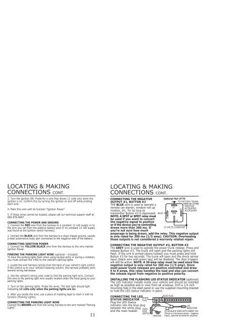
LOCATING & MAKINGCONNECTIONS CONT.3. Turn the ignition ON. Probe for a wire that shows 12 volts only when theignition is on. Confirm this by turning the ignition on and off while probingeach wire.4. Mark this wire with its function “Ignition Power”.5. If these wires cannot be located, please call our technical support staff at800-878-8007.CONNECTING THE POWER AND GROUND1. Connect the RED wire from the harness to a constant 12 volt supply or tothe wire you ran from the positive battery post (if no constant 12 volt supplywas found at the ignition switch harness).2. Connect the BLACK wire from the harness to a clean chassis ground, usuallya steel automotive body part connected to the negative side of the battery.CONNECTING IGNITION POWER1. Connect the YELLOW/BLACK wire from the harness to the wire marketIgnition Power.FINDING THE PARKING LIGHT WIRE (optional - included)To have the parking lights flash when using keyless entry or during a violation,you must connect the <strong>1402</strong> to the vehicle’s parking lights.1. Locate the wire harness coming from the back of your vehicle’s light control.If the control is on your vehicle’s steering column, the harness probably joinsseveral wiring harnesses.2. Use the vehicle’s wiring color code to find the parking light wire. Connectthis wire to the parking light wire usually located under the hood going to yourparking lights.3. Turn on the parking lights. Probe the wires. The test light should lightindicating 12 volts only when the parking lights are on.4. After you locate the wire, use a piece of masking tape to mark it with itsfunction (Parking Lights).CONNECTING THE PARKING LIGHT WIREConnect the BROWN wire from the wiring harness to the wire marked “ParkingLights”.11LOCATING & MAKINGCONNECTIONS CONT.CONNECTING THE NEGATIVEOUTPUT #1, BUTTON #2THE BLUE wire is used to operate aremote car starter, window roll-upmodule, etc. for as long astransmitter Button #2 is depressed.NOTE: A SPST or SPDT relay mustbe used if you want to convertthe negative signal to positiveor if the device you’re controllingdraws more than 200 ma. Ifyou’re not sure how muchOptional Part #775TO FACTORY TRUNKWIRE OR OTHERPOSITIVEACTIVATEDACCESSORYBLUE 87a12 VOLTS CONSTANTamperage is being drawn, add the relay. This negative outputis only rated for 200 ma (1/5 amp). CAUTION: Overloadingthese outputs is not considered a warranty related repair.CONNECTING THE NEGATIVE OUTPUT #2, BUTTON #3The GREY wire is used to operate the power trunk release. Press andrelease Button #3. The trunk will open and the parking lights willflash. If the unit is armed (doors locked) you must press and holdButton #3 for two seconds. The trunk will open and the shock sensorinput (black wire with green tag) will be disabled. The door triggerswill still be active. NOTE: A 30 amp relay must be used since thisnegative output is only rated for 200 ma (1/5 amp). Sincemost power trunk releases are positive controlled and draw5 to 6 amps, this relay handles the load and also can convertthe release signal from negative to positive polarity.INSTALLING THE FLASHING LED STATUS INDICATOR (optional)The LED indicator installs inside your vehicle and should be installedas high as possible and in view from all windows. Drill a 1/4 inchmounting hole in the dash panel or use the supplied mounting bracketto hold the LED status indicator in place.CONNECTING THE LEDWHITESTATUS INDICATOR PLUGPlug the LED Statusindicator into the blue plugbetween the white plugand the main header.OVER-RIDESWITCHBLUE PLUGLEDINDICATOR22 GA BLACK WIRE WITH GREEN TAG(Shock or microwave sensor - negativeGROUND input), optional accessories required‘