
You also want an ePaper? Increase the reach of your titles
YUMPU automatically turns print PDFs into web optimized ePapers that Google loves.
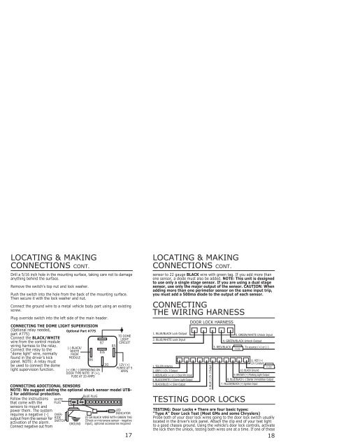
‘ ‘LOCATING & MAKINGLOCATING & MAKINGCONNECTIONS CONT.CONNECTIONS CONT.Drill a 5/16 inch hole in the mounting surface, taking care not to damageanything behind the surface.Remove the switch’s top nut and lock washer.Push the switch into the hole from the back of the mounting surface.Then secure it with the lock washer and nut.Connect the ground wire to a metal vehicle body part using an existingscrew.Plug override switch into the left side of the main header.CONNECTING THE DOME LIGHT SUPERVISION(Optional relay needed,Optional Part #775part #775)Connect the BLACK/WHITEwire from the control modulewiring harness to the relay.(-) BLACK/Connect the relay to theWHITE87a“dome light” wire, normally FROMfound in the driver’s kickMODULEpanel. NOTE: A relay mustbe used to connect the domelight supervision function. (+) OR (-) DEPENDING ONDOOR TYPE NOTE: IF (+),FUSE AT 20 AMPSFollow the instructionsthat come with thesensors to mount andpower them. The systemrequires a negative (-)output from the sensor foractivation of the alarm.Connect negative out fromWHITEPLUGCONNECTING ADDITIONAL SENSORSNOTE: We suggest adding the optional shock sensor model UTB-2 for additional protection.OVER-RIDESWITCHBLUE PLUGTO DOMELIGHTCIRCUIT12V (+)FUSED AT 5AMPSLEDINDICATOR22 GA BLACK WIRE WITH GREEN TAG(Shock or microwave sensor - negativeGROUND input), optional accessories required17sensor to 22 gauge BLACK wire with green tag. If you add more thanone sensor, a diode must also be added. NOTE: This unit is designedto use only a single stage sensor. If you are using a dual stagesensor, use only the major output of the sensor. CAUTION: Whenadding more than one perimeter sensor on the same input trip,you must add a 500ma diode to the output of each sensor.CONNECTINGTHE WIRING HARNESS1. BLUE/BLACK Lock Output2. BLUE/WHITE Lock Input1. YELLOW Antenna2. GREY (-) Ch. 3 Output3. RED/BLACK (+) or (-) Door Pin Input4. BLACK/WHITE (-) Dome Light Output5. BLACK/BLUE (+) Siren OutputDOOR LOCK HARNESS5. GREEN/WHITE Unlock Input4. GREEN/BLACK Unlock Output3. RED/BLACK To source (+) or (-)FUSETESTING DOOR LOCKS6. BLUE (-) Ch. 2 Output11. RED (+)12V ConstantFUSE10. BLACK Ground9. BROWN (+) Parking Light Output8. BLUE/BLACK (-) Starter Immobilizer Output7. YELLOW/BLACK (+) Ignition InputTESTING: Door Locks • There are four basic types:“Type A” Door Lock Test (Most GMs and some Chryslers)Probe both of your door lock wires going to the door lock switch usuallylocated in the driver’s kick panel. Attach the clip end of your test lightto a good chassis ground. Using the vehicle’s door lock controls, activatethe lock then the unlock, testing both wires one at a time. If one of these18