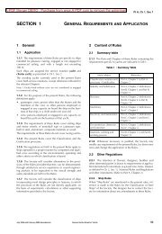
Chapter 4Table 1 : Documentation to be submittedDocumentDocument detailsMidship SectionScantling planWatertight subdivision bulkheads• required class characteristics• openings on decks and shell• corrosion protection• minimum and extreme drafts• loads on decks• block deckopenings, if anyWatertight and wash bulkheads <strong>of</strong> ballast tanks • location <strong>of</strong> air vents• tanks intended to be partially filled• procedures <strong>for</strong> tank filling and level and pressure controlMachinery foundationsmass <strong>of</strong> machineryDetails <strong>of</strong> section connections(constructional drawing)Wall shutters and similarGeneral plan <strong>of</strong> external doors and scuttlesGeneral plan <strong>of</strong> ventilation and manholesArrangement <strong>for</strong> handling <strong>of</strong> loadsStructure <strong>of</strong> load elevatorsuse <strong>of</strong> roomsrelevant hull stiffeningSea water intakes and overboard discharges in generalHydrostatic test planPumping diagramsStability calculations1.4 Operating Manual1.4.1 An Operating Manual is to be prepared <strong>for</strong> eachfloating dock, describing <strong>the</strong> operating condition.In addition to <strong>the</strong> characteristic elements <strong>of</strong> <strong>the</strong> floatingdock itself, <strong>the</strong> Manual, to be sent <strong>for</strong> in<strong>for</strong>mation to RINA,is to report <strong>the</strong> basic data assumed <strong>for</strong> <strong>the</strong> strength calculations(design lifting capacity, load distribution, etc.) andin<strong>for</strong>mation <strong>for</strong> verification <strong>of</strong> stability in <strong>the</strong> various operativeconditions.2 General requirements <strong>for</strong> design2.1 Stability2.1.1 General<strong>Floating</strong> docks having a length equal to or greater than 24 mare to be provided with suitable transverse stability characteristicscomplying with <strong>the</strong> requirements <strong>of</strong> this item [2.1].2.1.2 Loading conditionsStability calculations are to analyse <strong>the</strong> most severe operativeconditions, taking into account <strong>the</strong> heaviest weightpositions, including hanging loads and <strong>the</strong> possible effects<strong>of</strong> free surfaces <strong>of</strong> liquids in tanks.In particular, <strong>for</strong> dry docks, <strong>the</strong> loading conditions whichconsider water levels lapping <strong>the</strong> top edge <strong>of</strong> <strong>the</strong> block deckand <strong>the</strong> top part <strong>of</strong> <strong>the</strong> blocks <strong>the</strong>mselves are to be considered.Moreover, RINA may, at its discretion, request to carry out astability calculation <strong>for</strong> <strong>the</strong> case <strong>of</strong> an emerged floatingdock with displacement as close as possible to full load displacement,with a flooded compartment, eccentric and atone end <strong>of</strong> <strong>the</strong> dock, i.e. selected among those involving<strong>the</strong> most severe conditions from <strong>the</strong> point <strong>of</strong> view <strong>of</strong> stability.2.1.3 Intact stability requirementsIn general, <strong>for</strong> dry docks <strong>the</strong> initial metacentric transversalheight GM0 <strong>of</strong> <strong>the</strong> system ship plus dry dock, consideringall <strong>the</strong> corrections <strong>for</strong> liquid free surface effects, is to be notless than 1,5 m <strong>for</strong> docks with design lifting capacity up to10000 t.The above-mentioned metacentric height may be linearlyreduced <strong>for</strong> lifting capacities over 10000 t, up to a minimum<strong>of</strong> 1,0 m <strong>for</strong> lifting capacities equal to 50000 t orabove.2.1.4 Severe wind and rolling criterion (wea<strong>the</strong>rcriterion)a) AssumptionsThe ability <strong>of</strong> a floating dock to withstand <strong>the</strong> combinedeffects <strong>of</strong> beam wind and rolling is to be demonstrated14 <strong>Rules</strong> <strong>for</strong> floating docks 2010
Chapter 4<strong>for</strong> each standard condition <strong>of</strong> loading, with reference toFig 1 as follows:• <strong>the</strong> dock is subjected to a steady wind pressure actingperpendicular to <strong>the</strong> dock's centreline whichresults in a steady wind heeling lever (l w1 );• from <strong>the</strong> resultant angle <strong>of</strong> equilibrium (θ 0 ), <strong>the</strong> dockis assumed to roll owing to wave action to an angle<strong>of</strong> roll (θ 1 ) to windward;• <strong>the</strong> dock is <strong>the</strong>n subjected to a gust wind pressurewhich results in a gust wind heeling lever (l w2 );• free surface effects are to be accounted <strong>for</strong> in <strong>the</strong>standard conditions <strong>of</strong> loading.Figure 1 : Severe wind and rollingLeverb) CriteriaUnder <strong>the</strong> assumptions <strong>of</strong> a) above, <strong>the</strong> following criteriaare to be complied with:• <strong>the</strong> area "b" is to be equal to or greater than <strong>the</strong> area"a",where:a : Area above <strong>the</strong> GZ curve and below l w2 ,between θ R and <strong>the</strong> intersection <strong>of</strong> l w2with <strong>the</strong> GZ curveb : Area above <strong>the</strong> heeling lever l w2 andbelow <strong>the</strong> GZ curve, between <strong>the</strong> intersection<strong>of</strong> l w2 with <strong>the</strong> GZ curve and θ 2 .• <strong>the</strong> angle <strong>of</strong> heel under action <strong>of</strong> steady wind (θ 0 ) isto be limited to 16° or 80% <strong>of</strong> <strong>the</strong> angle <strong>of</strong> deckedge immersion, whichever is <strong>the</strong> lesser.c) Heeling leversThe wind heeling levers l w1 and l w2 , in m, referred to inb) above, are constant values at all angles <strong>of</strong> inclinationand are to be calculated as follows:l w1andl w2 = 1,5 l w1where:P : 504 N/m 2The value <strong>of</strong> P used <strong>for</strong> docks positioned inprotected locations may be reduced subjectto <strong>the</strong> approval <strong>of</strong> RINAGZθ 2 θ caAngle <strong>of</strong> heelθ 0θ 1PAZ= --------------------1000g∆blw 1lw 2A : Projected lateral area, in m 2 , <strong>of</strong> <strong>the</strong> portion<strong>of</strong> <strong>the</strong> dock and deck cargo above <strong>the</strong> waterline;Z : Vertical distance in m, from <strong>the</strong> centre <strong>of</strong> Ato <strong>the</strong> centre <strong>of</strong> <strong>the</strong> underwater lateral areaor approximately to a point at one half <strong>the</strong>draught;∆ : Displacement, in t;g : 9,81 m/s 2 .d) angles <strong>of</strong> heel:For <strong>the</strong> purpose <strong>of</strong> calculating <strong>the</strong> criteria <strong>of</strong> b) above,<strong>the</strong> angles in Fig 1 are defined as follows:θ 0 : Angle <strong>of</strong> heel, in degrees, under action <strong>of</strong>steady windθ 1 : Angle <strong>of</strong> roll, in degrees, to windward dueto wave action, calculated as follows:θ 2 : Angle <strong>of</strong> downflooding (θ f ) in degrees, ei<strong>the</strong>r50° or θ c , whichever is <strong>the</strong> lesserθ f : Angle <strong>of</strong> heel in degrees, at which openingsin <strong>the</strong> hull, superstructures or deckhouseswhich cannot be closed wea<strong>the</strong>rtightimmerse. In applying this criterion, smallopenings through which progressive floodingcannot take place need not be consideredas open;θ c : Angle in degrees, <strong>of</strong> second interceptbetween wind heeling lever l w2 and GZcurvesθ R = θ 0 = θ 1x 1 : Coefficient defined in Tab 2x 2 : Coefficient defined in Tab 3k : Coefficientk = 1,0 <strong>for</strong> a round-bilged dock having nobilge or bar keelsk = 0,7 <strong>for</strong> a dock having sharp bilgeFor a dock having no bilge keels, a bar keelor both, k is defined in Tab 4.DG : Distance in m, between <strong>the</strong> centre <strong>of</strong> gravityand <strong>the</strong> waterline (positive if centre <strong>of</strong> gravityis above <strong>the</strong> waterline, negative if it isbelow)T 1 : Mean moulded draught in m, <strong>of</strong> <strong>the</strong> docks : Factor defined in Tab 5.Note 1: The angle <strong>of</strong> roll θ 1 <strong>for</strong> docks with anti-rolling devices is tobe determined without taking into account <strong>the</strong> operations <strong>of</strong><strong>the</strong>se devices.Note 2: The angle <strong>of</strong> roll θ 1 may be obtained, in lieu <strong>of</strong> <strong>the</strong> above<strong>for</strong>mula, from model tests or full scale measurements.The rolling period T R , in s, is calculated as follows:T Rwhere:2CB= -------------GMθ 1 = 109kX 1 X 2 rs<strong>Rules</strong> <strong>for</strong> floating docks 2010 15