Chapter 4Table 7 : Table 7 : Grades <strong>of</strong> steel to be used <strong>for</strong> elements contributing to longitudinal strength, not includedamong those considered in Tab 2, but <strong>of</strong> particular local importanceThickness s ≤ 30 mm 30 < s ≤ 40 mm s > 40 mmNormal strength A and B B EHigher strength steels AH AH DHTable 8Lifting capacity ≤ 40000 t 50000 t 60000 t 70000 t 80000 t 90000 t 100000 tCoefficient C 0,8 0,85 0,89 0,92 0,95 0,97 0,993.2 <strong>Docks</strong> in rein<strong>for</strong>ced concrete or in prestressedrein<strong>for</strong>ced concrete3.2.1 <strong>Docks</strong> in rein<strong>for</strong>ced concrete or in pre-stressed rein<strong>for</strong>cedconcrete are considered by RINA on a case-by-casebasis.4 General requirements <strong>for</strong> scantlings4.1 General4.1.1 The scantlings <strong>of</strong> <strong>the</strong> dock are to be such that <strong>the</strong>indicative values <strong>of</strong> <strong>the</strong> state <strong>of</strong> <strong>the</strong> structure obtained byapplying <strong>the</strong> requirements <strong>for</strong> <strong>the</strong> check <strong>of</strong> <strong>the</strong> longitudinal,transverse and local strength given in <strong>the</strong> following itemsare no greater than <strong>the</strong> values <strong>of</strong> <strong>the</strong> allowable state.The scantlings <strong>of</strong> docks in rein<strong>for</strong>ced concrete or in prestressedrein<strong>for</strong>ced concrete are considered by RINA on acase-by-case basis.States exceeding <strong>the</strong> allowable state, but not in excess <strong>of</strong><strong>the</strong> limit state, may be permitted at RINA's discretion underparticular exceptional circumstances.4.2 Allowable state and limit state4.2.1 Definitionsa) Allowable state: <strong>the</strong> whole <strong>of</strong> <strong>the</strong> allowable stresses andglobal and local de<strong>for</strong>mations.b) Limit state: <strong>the</strong> whole <strong>of</strong> <strong>the</strong> stresses and global andlocal de<strong>for</strong>mations beyond which <strong>the</strong> structure loses itsfunctional characteristics.c) State <strong>of</strong> <strong>the</strong> structure: <strong>the</strong> whole <strong>of</strong> <strong>the</strong> stresses and globaland local de<strong>for</strong>mations <strong>of</strong> <strong>the</strong> structure.The allowable state and limit state are defined with referenceto <strong>the</strong> mechanical characteristics <strong>of</strong> materials and <strong>the</strong>stability conditions <strong>of</strong> elastic equilibrium <strong>of</strong> <strong>the</strong> structure.4.2.2 Steel docksa) Allowable stresses:σ id amm = 160/K, in N/mm 2τ am = 90/K, in N/mm 2The values <strong>of</strong> <strong>the</strong> coefficient K are those indicated inPart B <strong>of</strong> <strong>the</strong> <strong>Rules</strong>, in respect <strong>of</strong> <strong>the</strong> steel grade.b) Limit stresses:σ id lim = 0,9 σ snτ am = 0,52 σ snwhere σ sn is <strong>the</strong> nominal yielding stress <strong>of</strong> <strong>the</strong> material.Stress values less than those indicated in items a) and b)may be assumed, at RINA's discretion, with respect to <strong>the</strong>requirement <strong>of</strong> granting adequate safety <strong>for</strong> possible instabilityphenomena.4.3 Direct calculations4.3.1 When checking <strong>the</strong> constructional drawings, RINAmay consider material distribution and scantlings o<strong>the</strong>r thanthose obtained applying <strong>the</strong> requirements <strong>for</strong> <strong>the</strong> check <strong>of</strong>longitudinal, transversal and local strength given in <strong>the</strong> followingitems, provided that it is demonstrated, by means <strong>of</strong>direct calculations based on <strong>the</strong>oretical assumptions and/orexperimental results, that <strong>the</strong> allowable state or, <strong>for</strong> exceptionalload conditions, <strong>the</strong> limit state is not exceeded.Direct calculations made in accordance with <strong>the</strong> mostadvanced techniques are to be carried out wheneverrequested by RINA and in general in <strong>the</strong> case <strong>of</strong> unusualstructures or docks <strong>of</strong> large dimensions or particular characteristics.RINA reserves <strong>the</strong> right to require structural checks, alsotaking into account particular conditions which may exceptionallyoccur during <strong>the</strong> dock operation.The direct calculations are to be carried out <strong>for</strong> <strong>the</strong> mostsevere anticipated realistic load conditions.In particular, if <strong>the</strong> hydrostatic loads on <strong>the</strong> local structuresare determined with respect to <strong>the</strong> differential heads anticipatedduring operation and it is possible that, due to damage,said heads may be exceeded, <strong>the</strong> check with <strong>the</strong> loadcondition due to <strong>the</strong> extreme hydrostatic head which maybe assumed on <strong>the</strong> structure is to be carried out.4.4 Longitudinal strength4.4.1 Load conditionThe longitudinal strength is to be verified <strong>for</strong> dock operativeconditions, with <strong>the</strong> waterline corresponding to <strong>the</strong> pontoonfreeboard B le , with a structure with load equal to <strong>the</strong>design lifting capacity <strong>of</strong> <strong>the</strong> dock arranged on <strong>the</strong> floorand, as far as practicable, symmetrically on length.In <strong>the</strong> absence <strong>of</strong> more precise data, <strong>the</strong> conventional distribution<strong>of</strong> ship loads shown in Fig 2 may be assumed <strong>for</strong> drydocks.18 <strong>Rules</strong> <strong>for</strong> floating docks 2010
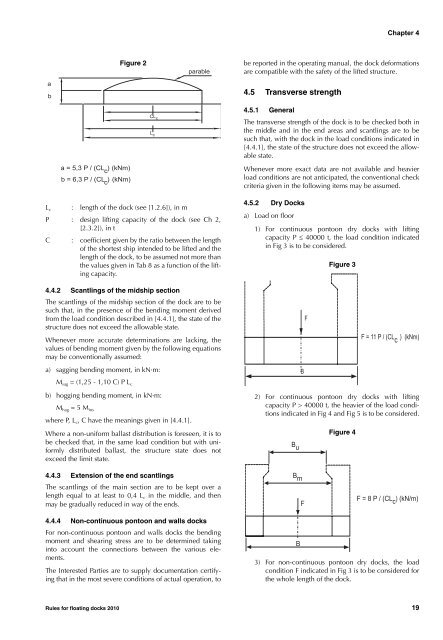
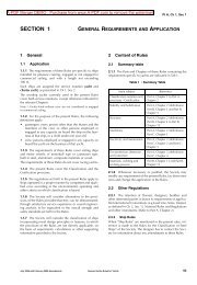
Chapter 4abFigure 2parablebe reported in <strong>the</strong> operating manual, <strong>the</strong> dock de<strong>for</strong>mationsare compatible with <strong>the</strong> safety <strong>of</strong> <strong>the</strong> lifted structure.4.5 Transverse strengtha = 5,3 P / (CL ) (kNm)cb = 6,3 P / (CL ) (kNm)cCL cL c4.5.1 GeneralThe transverse strength <strong>of</strong> <strong>the</strong> dock is to be checked both in<strong>the</strong> middle and in <strong>the</strong> end areas and scantlings are to besuch that, with <strong>the</strong> dock in <strong>the</strong> load conditions indicated in[4.4.1], <strong>the</strong> state <strong>of</strong> <strong>the</strong> structure does not exceed <strong>the</strong> allowablestate.Whenever more exact data are not available and heavierload conditions are not anticipated, <strong>the</strong> conventional checkcriteria given in <strong>the</strong> following items may be assumed.L c : length <strong>of</strong> <strong>the</strong> dock (see [1.2.6]), in mP : design lifting capacity <strong>of</strong> <strong>the</strong> dock (see Ch 2,[2.3.2]), in tC : coefficient given by <strong>the</strong> ratio between <strong>the</strong> length<strong>of</strong> <strong>the</strong> shortest ship intended to be lifted and <strong>the</strong>length <strong>of</strong> <strong>the</strong> dock, to be assumed not more than<strong>the</strong> values given in Tab 8 as a function <strong>of</strong> <strong>the</strong> liftingcapacity.4.5.2 Dry <strong>Docks</strong>a) Load on floor1) For continuous pontoon dry docks with liftingcapacity P ≤ 40000 t, <strong>the</strong> load condition indicatedin Fig 3 is to be considered.Figure 34.4.2 Scantlings <strong>of</strong> <strong>the</strong> midship sectionThe scantlings <strong>of</strong> <strong>the</strong> midship section <strong>of</strong> <strong>the</strong> dock are to besuch that, in <strong>the</strong> presence <strong>of</strong> <strong>the</strong> bending moment derivedfrom <strong>the</strong> load condition described in [4.4.1], <strong>the</strong> state <strong>of</strong> <strong>the</strong>structure does not exceed <strong>the</strong> allowable state.Whenever more accurate determinations are lacking, <strong>the</strong>values <strong>of</strong> bending moment given by <strong>the</strong> following equationsmay be conventionally assumed:a) sagging bending moment, in kN·m:M sag = (1,25 - 1,10 C) P L cBFF = 11 P / (CL c ) (kNm)b) hogging bending moment, in kN·m:M hag = 5 M inswhere P, L c , C have <strong>the</strong> meanings given in [4.4.1].Where a non-uni<strong>for</strong>m ballast distribution is <strong>for</strong>eseen, it is tobe checked that, in <strong>the</strong> same load condition but with uni<strong>for</strong>mlydistributed ballast, <strong>the</strong> structure state does notexceed <strong>the</strong> limit state.2) For continuous pontoon dry docks with liftingcapacity P > 40000 t, <strong>the</strong> heavier <strong>of</strong> <strong>the</strong> load conditionsindicated in Fig 4 and Fig 5 is to be considered.B uFigure 44.4.3 Extension <strong>of</strong> <strong>the</strong> end scantlingsThe scantlings <strong>of</strong> <strong>the</strong> main section are to be kept over alength equal to at least to 0,4 L c in <strong>the</strong> middle, and <strong>the</strong>nmay be gradually reduced in way <strong>of</strong> <strong>the</strong> ends.B mFF=8P/(CL ) (kN/m)c4.4.4 Non-continuous pontoon and walls docksFor non-continuous pontoon and walls docks <strong>the</strong> bendingmoment and shearing stress are to be determined takinginto account <strong>the</strong> connections between <strong>the</strong> various elements.The Interested Parties are to supply documentation certifyingthat in <strong>the</strong> most severe conditions <strong>of</strong> actual operation, toB3) For non-continuous pontoon dry docks, <strong>the</strong> loadcondition F indicated in Fig 3 is to be considered <strong>for</strong><strong>the</strong> whole length <strong>of</strong> <strong>the</strong> dock.<strong>Rules</strong> <strong>for</strong> floating docks 2010 19