Rules for the Classification of Floating Docks - Boat Design Net
Rules for the Classification of Floating Docks - Boat Design Net
Rules for the Classification of Floating Docks - Boat Design Net

You also want an ePaper? Increase the reach of your titles
YUMPU automatically turns print PDFs into web optimized ePapers that Google loves.
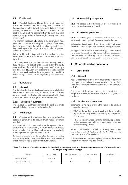
Chapter 42.2 Freeboard2.2.1 The shell freeboard Bl i , which is <strong>the</strong> minimum distance,in millimetres, from <strong>the</strong> floating dock upper deck to<strong>the</strong> waterline with <strong>the</strong> dock at its extreme draft, is to be, ingeneral, not less than 1000 mm. Particular attention is to bepaid to <strong>the</strong> value <strong>of</strong> <strong>the</strong> freeboard Bl i in <strong>the</strong> event that shellopenings not provided with watertight closing appliancesare arranged.The pontoon freeboard Bl e , which is <strong>the</strong> distance, in mm,measured in way <strong>of</strong> <strong>the</strong> longitudinal plane <strong>of</strong> symmetryfrom <strong>the</strong> block deck to <strong>the</strong> waterline, when <strong>the</strong> dock is bearinga load equal to its design capacity, is to be, in general,not less than 300 mm.When <strong>the</strong> block deck is provided with a camber, <strong>the</strong> minimumfreeboard Bl e is to be not less than 75 mm at <strong>the</strong> pontoonside.The floating dock is to be provided with a safety deck sothat, when all <strong>the</strong> ballast tanks located below <strong>the</strong> safetydeck are filled, <strong>the</strong> dock is floating with a draft ensuring aside freeboard Bl i . Alternative solutions to <strong>the</strong> arrangement<strong>of</strong> <strong>the</strong> safety deck, such as <strong>the</strong> arrangement <strong>of</strong> air cushionsbelow <strong>the</strong> upper deck, will be subject to special consideration.2.3 Subdivision2.3.1 GeneralThe dock is to be longitudinally and transversely subdividedinto watertight compartments, in order to make it possibleto safely obtain <strong>the</strong> ballast distributions required in loadconditions and in <strong>the</strong> anticipated service conditions.2.3.2 Extension <strong>of</strong> bulkheadsThe longitudinal and transverse watertight bulkheads are toextend, in height, at least up to <strong>the</strong> safety deck.2.4 Ventilation2.4.1 Quarters, service and machinery spaces and c<strong>of</strong>ferdamsare generally to be provided with natural or <strong>for</strong>cedventilation.Associated air intakes and outlets to <strong>the</strong> open are to bearranged, as far as practicable, at heights not less than thoserequired in Part B <strong>of</strong> <strong>the</strong> <strong>Rules</strong> and are to be provided withcut-draught shutters operable from outside.Particular precautions are to be taken <strong>for</strong> systems servingspaces likely to be contaminated by toxicants or materialswhich may give rise to explosive mixtures with air.2.5 Accessibility <strong>of</strong> spaces2.5.1 All spaces and c<strong>of</strong>ferdams are to be accessible <strong>for</strong>inspection, maintenance and repair.2.6 Corrosion protection2.6.1 All metallic parts are to receive at least two coats <strong>of</strong>antirust paint <strong>of</strong> recognised effectiveness and adhesion.Such coating is not required <strong>for</strong> internal surfaces <strong>of</strong> spacesintended to contain liquid fuel or mineral or vegetable oils.The application <strong>of</strong> paints or o<strong>the</strong>r coatings is to be carriedout in accordance with good practice and coating manufacturerprescriptions and taking into due account <strong>the</strong> compatibility<strong>of</strong> <strong>the</strong> types <strong>of</strong> coatings used in subsequent layers.3 Materials and connections3.1 Steel docks3.1.1 GeneralSteels used <strong>for</strong> <strong>the</strong> construction <strong>of</strong> docks are to comply with<strong>the</strong> requirements indicated in Part D, Ch 2, Sec 1 <strong>of</strong> <strong>the</strong><strong>Rules</strong>, or to have equivalent characteristics, at <strong>the</strong> discretion<strong>of</strong> RINA.Connections <strong>of</strong> <strong>the</strong> various parts are to be carried out incompliance with <strong>the</strong> requirements <strong>of</strong> Part B, Ch 12, Sec 1 <strong>of</strong><strong>the</strong> <strong>Rules</strong>.3.1.2 Grades and types <strong>of</strong> steelDepending on <strong>the</strong> types <strong>of</strong> steel, <strong>the</strong> grades to be used arein general those given in:• Tab 6 <strong>for</strong> <strong>the</strong> shell <strong>of</strong> <strong>the</strong> safety deck and <strong>the</strong> upper platingstrake <strong>of</strong> wing walls contributing to longitudinalstrength and• Tab 7 <strong>for</strong> <strong>the</strong> remaining elements contributing to longitudinalstrength, not included in <strong>the</strong> above, but <strong>of</strong> particularlocal importance.For structural elements not included among those consideredin Tab 6 and Tab 7, steel grades A, B or AH are to beused, irrespective <strong>of</strong> <strong>the</strong> thickness.Wherever necessary, steels <strong>of</strong> higher grades than those mentionedabove may be required by RINA.Table 6 : Grades <strong>of</strong> steel to be used <strong>for</strong> <strong>the</strong> shell <strong>of</strong> <strong>the</strong> safety deck and <strong>the</strong> upper plating strake <strong>of</strong> wing walls contributingto longitudinal strengthThickness s ≤ 20 mm 20 < s ≤ 25 mm 25 < s ≤ 40 mm s > 40 mmNormal strength A and B B D EHigher strength steels AH AH DH EH<strong>Rules</strong> <strong>for</strong> floating docks 2010 17