


Create successful ePaper yourself
Turn your PDF publications into a flip-book with our unique Google optimized e-Paper software.
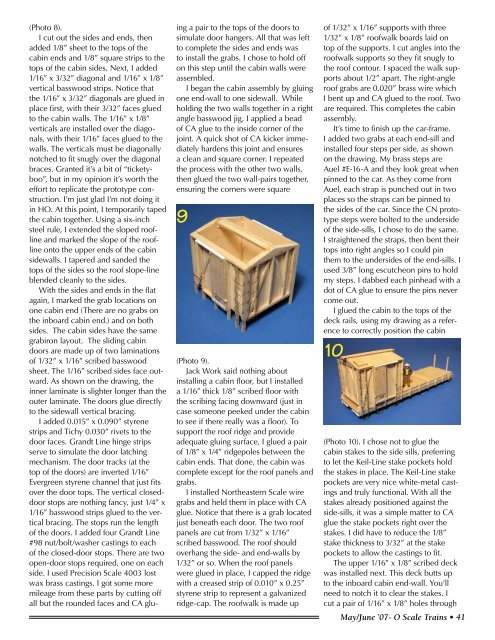
(Photo 8).I cut out the sides and ends, thenadded 1/8” sheet to the tops of thecabin ends and 1/8” square strips to thetops of the cabin sides. Next, I added1/16” x 3/32” diagonal and 1/16” x 1/8”vertical basswood strips. Notice thatthe 1/16” x 3/32” diagonals are glued inplace first, with their 3/32” faces gluedto the cabin walls. The 1/16” x 1/8”verticals are installed over the diagonals,with their 1/16” faces glued to thewalls. The verticals must be diagonallynotched to fit snugly over the diagonalbraces. Granted it’s a bit of “ticketyboo”,but in my opinion it’s worth theeffort to replicate the prototype construction.I’m just glad I’m not doing itin HO. At this point, I temporarily tapedthe cabin together. Using a six-inchsteel rule, I extended the sloped rooflineand marked the slope of the rooflineonto the upper ends of the cabinsidewalls. I tapered and sanded thetops of the sides so the roof slope-lineblended cleanly to the sides.With the sides and ends in the flatagain, I marked the grab locations onone cabin end (There are no grabs onthe inboard cabin end.) and on bothsides. The cabin sides have the samegrabiron layout. The sliding cabindoors are made up of two laminationsof 1/32” x 1/16” scribed basswoodsheet. The 1/16” scribed sides face outward.As shown on the drawing, theinner laminate is slighter longer than theouter laminate. The doors glue directlyto the sidewall vertical bracing.I added 0.015” x 0.090” styrenestrips and Tichy 0.030” rivets to thedoor faces. Grandt Line hinge stripsserve to simulate the door latchingmechanism. The door tracks (at thetop of the doors) are inverted 1/16”Evergreen styrene channel that just fitsover the door tops. The vertical closeddoorstops are nothing fancy, just 1/4” x1/16” basswood strips glued to the verticalbracing. The stops run the lengthof the doors. I added four Grandt Line#98 nut/bolt/washer castings to eachof the closed-door stops. There are twoopen-door stops required, one on eachside. I used Precision <strong>Scale</strong> 4003 lostwax brass castings. I got some moremileage from these parts by cutting offall but the rounded faces and CA gluinga pair to the tops of the doors tosimulate door hangers. All that was leftto complete the sides and ends wasto install the grabs. I chose to hold offon this step until the cabin walls wereassembled.I began the cabin assembly by gluingone end-wall to one sidewall. Whileholding the two walls together in a rightangle basswood jig, I applied a beadof CA glue to the inside corner of thejoint. A quick shot of CA kicker immediatelyhardens this joint and ensuresa clean and square corner. I repeatedthe process with the other two walls,then glued the two wall-pairs together,ensuring the corners were square9(Photo 9).Jack Work said nothing aboutinstalling a cabin floor, but I installeda 1/16” thick 1/8” scribed floor withthe scribing facing downward (just incase someone peeked under the cabinto see if there really was a floor). Tosupport the roof ridge and provideadequate gluing surface, I glued a pairof 1/8” x 1/4” ridgepoles between thecabin ends. That done, the cabin wascomplete except for the roof panels andgrabs.I installed Northeastern <strong>Scale</strong> wiregrabs and held them in place with CAglue. Notice that there is a grab locatedjust beneath each door. The two roofpanels are cut from 1/32” x 1/16”scribed basswood. The roof shouldoverhang the side- and end-walls by1/32” or so. When the roof panelswere glued in place, I capped the ridgewith a creased strip of 0.010” x 0.25”styrene strip to represent a galvanizedridge-cap. The roofwalk is made upof 1/32” x 1/16” supports with three1/32” x 1/8” roofwalk boards laid ontop of the supports. I cut angles into theroofwalk supports so they fit snugly tothe roof contour. I spaced the walk supportsabout 1/2” apart. The right-angleroof grabs are 0.020” brass wire whichI bent up and CA glued to the roof. Twoare required. This completes the cabinassembly.It’s time to finish up the car-frame.I added two grabs at each end-sill andinstalled four steps per side, as shownon the drawing. My brass steps areAuel #E-16-A and they look great whenpinned to the car. As they come fromAuel, each strap is punched out in twoplaces so the straps can be pinned tothe sides of the car. Since the CN prototypesteps were bolted to the undersideof the side-sills, I chose to do the same.I straightened the straps, then bent theirtops into right angles so I could pinthem to the undersides of the end-sills. Iused 3/8” long escutcheon pins to holdmy steps. I dabbed each pinhead with adot of CA glue to ensure the pins nevercome out.I glued the cabin to the tops of thedeck rails, using my drawing as a referenceto correctly position the cabin10(Photo 10). I chose not to glue thecabin stakes to the side sills, preferringto let the Keil-Line stake pockets holdthe stakes in place. The Keil-Line stakepockets are very nice white-metal castingsand truly functional. With all thestakes already positioned against theside-sills, it was a simple matter to CAglue the stake pockets right over thestakes. I did have to reduce the 1/8”stake thickness to 3/32” at the stakepockets to allow the castings to fit.The upper 1/16” x 1/8” scribed deckwas installed next. This deck butts upto the inboard cabin end-wall. You’llneed to notch it to clear the stakes. Icut a pair of 1/16” x 1/8” holes throughMay/June ’07- O <strong>Scale</strong> <strong>Trains</strong> • 41


