Model 28623TN - Ready Remote
Model 28623TN - Ready Remote
Model 28623TN - Ready Remote

You also want an ePaper? Increase the reach of your titles
YUMPU automatically turns print PDFs into web optimized ePapers that Google loves.
<strong>Model</strong> <strong>28623TN</strong>➤Owner’s/Installation GuideOEM Series
limited lifetime consumer warrantyDirected Electronics (hereinafter "Directed") promises to the original purchaser to repairor replace with a comparable reconditioned Directed DIY remote start unit if thisDirected DIY remote start unit (hereinafter "Unit"), excluding without limitation, anyremote transmitters or associated accessories, proves defective in materials or workmanshipunder normal use for the life of the vehicle which the Unit is originally installed.During this period, so long as the Unit remained installed in the original vehicle, Directedwill at its option, repair or replace this Unit if it is proved defective in workmanship ormaterial PROVIDED the Unit is returned to Directed's warranty department at OneViper Way, Vista, CA 92081, along with $20 postage and handling fee, a bill of sale orother dated proof of purchase bearing the following information: Date of purchase, nameand location of the merchant who sold the Unit, and product description. This warrantydoes not cover labor costs for the removal or reinstallation of the Unit. This warranty isnon-transferable and does not apply to any Unit that has been modified or used in a mannercontrary to its intended purpose, and this warranty does not cover damage to any Unitcaused by installation or removal of the Unit. This warranty is void if the Unit has beendamaged by accident or unreasonable use, neglect, improper service or other causes notarising out of defects in materials or workmanship. Directed makes no warranty againsttheft of a vehicle or its contents.THE FOREGOING WARRANTY IS THE EXCLUSIVE PRODUCT WARRANTY,OTHERWISE, ALL WARRANTIES INCLUDING BUT NOT LIMITED TOEXPRESS WARRANTY, IMPLIED WARRANTY, WARRANTY OF MER-CHANTABILITY, OR FITNESS FOR A PARTICULAR PURPOSE ARE EXPRESSLYEXCLUDED AND DISCLAIMED TO THE MAXIMUM EXTENT ALLOWED BYLAW, AND DIRECTED NEITHER ASSUMES NOR AUTHORIZES ANY PERSONTO ASSUME FOR IT ANY LIABILITY IN CONNECTION WITH THE SALE OFTHE PRODUCT. DIRECTED HAS ABSOLUTELY NO LIABILITY FOR ANYAND ALL ACTS OF THIRD PARTIES INCLUDING ITS AUTHORIZED DEAL-ERS OR INSTALLERS. SOME STATES DO NOT ALLOW THE LIMITATION ONHOW LONG AN IMPLIED WARRANTY LASTS, SO THE ABOVE LIMITATIONMAY NOT APPLY TO YOU.LIMITATION OF DAMAGES AND LIABILITY. CONSUMER'S REMEDY IS LIM-ITED TO REPAIR OR REPLACEMENT OF THE UNIT, AND IN NO EVENTSHALL DIRECTED'S LIABILITY EXCEED THE PURCHASE PRICE OF THEUNIT. IN ANY EVENT, DIRECTED SHALL NOT BE LIABLE FOR ANY DAM-AGES INCLUDING, BUT NOT LIMITED TO, ANY DIRECT, INDIRECT, INCI-DENTAL, SPECIAL, PUNITIVE OR CONSEQUENTIAL DAMAGES, LOSTPROFITS, LOST SAVINGS, OR, TO THE EXTENT ALLOWED BY APPLICABLELAW, DAMAGES RESULTING FROM DEATH OR INJURY ARISING OUT OF© 2006 Directed Electronicsi
OR IN CONNECTION WITH THE INSTALLATION, USE, IMPROPER USE, ORINABILITY TO USE, THE PRODUCT, EVEN IF THE PARTY HAS BEENADVISED OF THE POSSIBILITY OF SUCH DAMAGES. SOME STATES DONOT ALLOW THE EXCLUSION OF LIMITATION OF INCIDENTAL OR CON-SEQUENTIAL DAMAGES, SO THE ABOVE LIMITATIONS OR EXCLUSIONMAY NOT APPLY TO YOU. THE CONSUMER AGREES AND CONSENTS THATALL DISPUTES BETWEEN THE CONSUMER AND DIRECTED SHALL BERESOLVED IN ACCORDANCE WITH CALIFORNIA LAWS IN SAN DIEGOCOUNTY, CALIFORNIA.IMPORTANT NOTE:This product warranty is automatically void if its date code or serial number is defaced,missing, or altered.Make sure you have all of the following information from your dealer:A clear copy of the sales receipt, showing the following:➤➤➤Date of purchaseAuthorized dealer's company name and addressItem numberii© 2006 Directed Electronics
table of contentslimited lifetime consumer warranty. . . . . . . . . . . . . . . . . . . . . . . . . . . . . . . . . . . . . . . . iInstall Guide . . . . . . . . . . . . . . . . . . . . . . . . . . . . . . . . . . . . . . . . . . . . . . . . . . . . . . . . 3what is included . . . . . . . . . . . . . . . . . . . . . . . . . . . . . . . . . . . . . . . . . . . . . . . . . . 3installation tools. . . . . . . . . . . . . . . . . . . . . . . . . . . . . . . . . . . . . . . . . . . . . . . . . . 3important information . . . . . . . . . . . . . . . . . . . . . . . . . . . . . . . . . . . . . . . . . . . . . 4system maintenance . . . . . . . . . . . . . . . . . . . . . . . . . . . . . . . . . . . . . . . . . . . . . . 4fcc/id notice . . . . . . . . . . . . . . . . . . . . . . . . . . . . . . . . . . . . . . . . . . . . . . . . . . . . 5warning! safety first . . . . . . . . . . . . . . . . . . . . . . . . . . . . . . . . . . . . . . . . . . . . . . . 5Wiring Quick Reference Guide . . . . . . . . . . . . . . . . . . . . . . . . . . . . . . . . . . . . . . . . . . 7H1 Harness - 6 pin connector . . . . . . . . . . . . . . . . . . . . . . . . . . . . . . . . . . . . . . . 8H2 Harness - 6 pin connector . . . . . . . . . . . . . . . . . . . . . . . . . . . . . . . . . . . . . . . 9relay heavy gauge wires. . . . . . . . . . . . . . . . . . . . . . . . . . . . . . . . . . . . . . . . . . . . 10Installation Overview . . . . . . . . . . . . . . . . . . . . . . . . . . . . . . . . . . . . . . . . . . . . . 11Step 1, Heavy Gauge Wire Connections . . . . . . . . . . . . . . . . . . . . . . . . . . . . . . 12Step 2, H1, Main Harness Connections. . . . . . . . . . . . . . . . . . . . . . . . . . . . . . . 19Step 3, H2 Harness . . . . . . . . . . . . . . . . . . . . . . . . . . . . . . . . . . . . . . . . . . . . . . 23Step 4, Mounting the Receiver/Antenna . . . . . . . . . . . . . . . . . . . . . . . . . . . . . . 28Step 5, Immobilizer Bypass Modules . . . . . . . . . . . . . . . . . . . . . . . . . . . . . . . . . 30Step 6, Programming . . . . . . . . . . . . . . . . . . . . . . . . . . . . . . . . . . . . . . . . . . . . . 31<strong>Remote</strong> Start Diagnostics . . . . . . . . . . . . . . . . . . . . . . . . . . . . . . . . . . . . . . . . . . 40Testing the system . . . . . . . . . . . . . . . . . . . . . . . . . . . . . . . . . . . . . . . . . . . . . . . 43Troubleshooting . . . . . . . . . . . . . . . . . . . . . . . . . . . . . . . . . . . . . . . . . . . . . . . . . 46Owner’s Guide . . . . . . . . . . . . . . . . . . . . . . . . . . . . . . . . . . . . . . . . . . . . . . . . . . . . . 50Transmitter Button Configuration . . . . . . . . . . . . . . . . . . . . . . . . . . . . . . . . . . . 51<strong>Remote</strong> Start Features . . . . . . . . . . . . . . . . . . . . . . . . . . . . . . . . . . . . . . . . . . . . 52Convenience Features. . . . . . . . . . . . . . . . . . . . . . . . . . . . . . . . . . . . . . . . . . . . . 59Glossary of terms . . . . . . . . . . . . . . . . . . . . . . . . . . . . . . . . . . . . . . . . . . . . . . . . 61Notes . . . . . . . . . . . . . . . . . . . . . . . . . . . . . . . . . . . . . . . . . . . . . . . . . . . . . . . . . . . . . 62quick reference guide: . . . . . . . . . . . . . . . . . . . . . . . . . . . . . . . . . . . . . . . . . . . . . . . . 63© 2006 Directed Electronics1
2 © 2006 Directed Electronics
Install Guidewhat is includedControl Module6-Pin Main H1 Harness6-Pin H2 Secondary HarnessHeavy Gauge WiresAntenna and cableTwo 3-button remotesCrash code cardCombination Momentary Switch and LEDHood Pin SwitchHardware KitAdditional parts may be required (such as relays or bypass).installation toolsDigital Multi-MeterDrill1/4 Drill Bit (for hood pin switch)Screwdrivers (Phillips and Flathead)Wire StripperSolder IronElectrical TapePliersCrimping Toolnote: The installation tools listed above may beoptional and those required will vary depending onyour vehicle.© 2006 Directed Electronics3
important informationCongratulations on the purchase of your remote start system. Thissystem allows you the convenience of remotely starting your vehiclewith the push of a button as well as other optional features.Properly installed, this system will provide years of trouble-freeoperation.Please take the time to carefully read this User’s Guide in itsentirety prior to installing your system.You can print additional or replacement copies of this manualby accessing the Directed web site atwww.autocommand.com.important! If you are not comfortable working withelectronics or unfamiliar with the tools required,please contact your local dealer for advice or ask tohave the remote start professionally installed to avoidcostly damages. Failure to properly install the remotestarter may result in property damage, personal injury,or both.➜system maintenanceThe system requires no specific maintenance. Your transmitteris powered by a miniature 12-volt battery (type 23A) that willlast approximately one year under normal use. When thebattery begins to weaken, the operating range will bereduced.4 © 2006 Directed Electronics
➜fcc/id noticeThis device complies with Part 15 of FCC rules. Operation issubject to the following conditions: (1) This device may notcause harmful interference, and (2) This device must acceptany interference received, including interference that maycause undesirable operation.Changes or modifications not expressly approved by the partyresponsible for compliance could void the user's authority tooperate this device.warning! safety firstThe following safety warnings must be observed at all times:When properly installed, this system can start the vehiclevia a command signal from the remote control transmitter.Therefore, never operate the system in an areathat does not have adequate ventilation. The followingprecautions are the sole responsibility of the user;however, the following recommendations should be madeto all users of this system:1. Never operate the system in an enclosed or partiallyenclosed area without ventilation (such as a garage).2. When parking in an enclosed or partially enclosedarea or when having the vehicle serviced, the remotestart system must be disabled by placing the systeminto Valet Mode.3. It is the user's sole responsibility to properly handleand keep out of reach from children all remotecontrol units to assure that the system does notunintentionally remote start the vehicle.4. THE USER MUST INSTALL A CARBON MONOXIDEDETECTOR IN OR ABOUT THE LIVING AREA ADJACENT© 2006 Directed Electronics5
TO THE VEHICLE. ALL DOORS LEADING FROM ADJACENTLIVING AREAS TO THE ENCLOSED OR PARTIALLYENCLOSED VEHICLE STORAGE AREA MUST AT ALL TIMESREMAIN CLOSED.Use of this product in a manner contrary to its intendedmode of operation may result in property damage, personalinjury, or death. Except when performing the Safety Checkoutlined in this user’s guide, (1) Never remotely start thevehicle with the vehicle in gear, and (2) Never remotelystart the vehicle with the keys in the ignition.After the remote start module has been installed, test theremote start module in accordance with the Safety Checkoutlined in this installation guide. If the vehicle startswhen performing the Neutral Safety Shutdown Circuit test,the remote start unit has not been properly installed. Theremote start module must be removed or properly reinstalledso that the vehicle does not start in gear. OPERA-TION OF THE REMOTE START MODULE IF THE VEHICLESTARTS IN GEAR IS CONTRARY TO ITS INTENDED MODE OFOPERATION. OPERATING THE REMOTE START SYSTEM UNDERTHESE CONDITIONS MAY RESULT IN PROPERTY DAMAGE ORPERSONAL INJURY. IMMEDIATELY CEASE THE USE OF THEUNIT AND REPAIR OR DISCONNECT THE INSTALLED REMOTESTART MODULE. DIRECTED WILL NOT BE HELD RESPON-SIBLE OR PAY FOR INSTALLATION OR REINSTALLATIONCOSTS.6 © 2006 Directed Electronics
Wiring Quick Reference GuideHeavy GaugeWiresBLUE WHITE (+)inputPINKYELLOWPINKGREEN (+) output to ign/acc2 circuit© 2006 Directed ElectronicsFused lightflash jumper Black (-)Heavy guageground wireMOMENTARY SWITCHH1YELLOW (+/-) parking light outputBROWN/WHITE (-) factory alarm disarm outputVIOLET (-) negative hood pin shutdown outputORANGE (+) brake inputWHITE/BLACK (-) 400mA status outputRED/WHITE (-) remote start activationANTENNA CABLE PORTGREEN Tachometer inputBLUE (-) 400mA horn/siren outputRED/BLACK (-) wait-to-start inputYELLOW/GREEN (+) ignition outputBROWN (-) 400mA RAP, Dome light, Starter kill outputYELLOW/BROWN (-) 400mA Headlight outputH27
H2 Harness - 6 pin connectorH2/1H2/2H2/3H2/4H2/5_______________GREENBLUERED/BLACKYELLOW/GREENBROWNTachometer input(-) 400mA horn/siren output(-) wait-to-start input(+) ignition output(-) 400mA RAP OutputH2/6___YELLOW/BROWN(-) 400mA headlight outputPin # Color NoteH2/1 Green Use this wire if the vehicle fails to start correctly involtage modeH2/2 Blue Negative output to horn or siren circuit. If your horn ispositive, use a relay.H2/3 Red/Black Used on diesel engines only. Connects to wait-to-startwireH2/4 Yellow/Green Ignition output. Connect this wire to the ignition inputof an aftermarket alarm system.H2/5 Brown Retained accessory shutdown or factory rearm output.Connect this wire to factory arm wire if equiped or todoor trigger wire if your vehicle’s accessories stay onafter remote start finishes cycle.H2/6 Yellow/Brown Headlight output. Connect this wire to headlight wirein car. If headlights are positive, a relay is required.© 2006 Directed Electronics9
elay heavy gauge wires12345_______________GREENPINKBLUEWHITEPINK(+) Ign2 or Acc2 output(+) 12 volt input(+) ignition 1 output(+) accessory output(+) 12 volt input6___YELLOW(+) starter outputBLACK(-) ground10 © 2006 Directed Electronics
Installation OverviewBe sure to read this section thoroughly in its entirety before startingthe installation. Pay special attention to all warnings to preventpersonal injury or damage to your vehicle.Visit our 24-hour technical web site (www.autocommand.com) toget a vehicle-specific wiring guide prior to starting this installation.Have your crash code number handy when contacting tech supportor visiting the web site. During the installation if you are unableto find answers to your questions on the web site, call 1-800-477-1382 for live technical assistance. Please note that live technicalsupport is available Monday-Friday 6am-6pm PST, and Saturday-Sunday 7am-3:30pm PST.WARNING!➤➤➤Verify that the transmission is set to park and thatthe parking brake is set before beginning installation.On vehicles with air bags or supplemental restraintsystems (SRS) you may notice a bright yellow tubewith small wires in it marked SRS underneath thesteering column near the key cylinder. DO NOT tamperor unplug these for any reason to prevent costly damagesto your vehicle or personal injury. Tamperingmay cause unintended deployment of airbags.This system is intended for automatic, fuel-injectedvehicles only. Installation in any other vehicle is contraryto its intended use.© 2006 Directed Electronics11
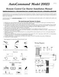
Step 1, Heavy Gauge Wire ConnectionsGround WireThe BLACK wire connects to the pin next to the light flash jumperfuse. First strip back a ¾-inch section of the insulation off theBLACK wire and crimp a ring terminal (not provided) to that wire.Locate a clean, paint-free metal surface in the drivers kick panel(do not ground on dash). Using a self-tapping screw, drill thescrew with the ring terminal to the kick panel. Once screwed down,pull on the wire to ensure a good connection.SELF-TAPPINGBOLT OR SCREWDIA-591NOTE: REMOVE ANY PAINTBELOW RING CONNECTORRINGTERMINALGROUNDWIREConstant Power and Ignition wiresAlmost all your power and ignition wires can be found behind thekey cylinder under the lower driver's side dash panel. Using theappropriate hand tools, remove the lower dash panel taking carenot to break any parts. If the panel does not come off easily, checkfor any additional screws you may have missed.12 © 2006 Directed Electronics
Once the lower dash panel has been removed, locate the ignitionharness at the back of the key cylinder. This is usually a group ofheavy gauge wires (approximate 14ga.).Place the black lead of the LED tester to a clean metal surface inthe kick panel area and secure it. Probe one of the thicker gaugewires. The ignition wire colors of your specific vehicle can beobtained at www.autocommand.com.note! More problems are attributed to poor groundconnections than any other cause. Take extra careto ensure the ground is a clean metal-to-metalcontact and secure.Testing for Constant Power WiresWARNING! Before making any connection to constantbattery power make sure that the two 30 amp fusesare removed from the fuse holders on the two pink 12VOLT wires. Failure to do so may cause fire or shortingof sensitive electrical components.© 2006 Directed Electronics13
With the key in the off position, test the suspect wire. Theconstant power wire will read 12V on the multimeter. Once theconstant power wire has been identified, solder the two heavygauge 12 VOLT wires (PINK) from the control module to it andwrap the connection with electrical tape.note! If the vehicle has more than one constantpower wire, utilize two of them. Connect one of theheavy gauge PINK wires to one of the constantpower wires and the other heavy gauge PINK wire tothe other constant power wire.Testing for Ignition WiresWith the multimeter lead still connected in the kick panel, locatethe suspected ignition wire. It will test differently than constant12 volts. Place the red lead of the multimeter on the suspectedwire. With the key in the off position the multimeter will read 0.Turn the key to the on position and the multimeter will read 12volts. Now, watching your multimeter, turn the key to the crankposition. If the 12 volts stays on, then you have found your ignitionwire. If the wire tests correctly, solder the BLUE heavy gaugewire to it and wrap the connection with electrical tape.If the vehicle requires more than one ignition as per the web siteinformation, follow the same test procedure and solder the GREENheavy gauge wire to it then wrap the connection with electricaltape. If your vehicle has only one ignition wire, secure the GREENwire and dress it out of the way.14 © 2006 Directed Electronics
If your vehicle requires more than two ignitions, an additionalrelay (not provided) is required. Refer to the diagram below.+12 VDC CONSTANT (FUSED 20A)2 nd IGNITION RELAY(NOT PROVIDED)TO 2 nd IGNITION8786 87A 8530GROUNDTO 2 nd IGNITION+12 VDC CONSTANT (FUSED 20A)3 rd IGNITION RELAY(NOT PROVIDED)GREEN (+) OUTPUTTO 2 nd IGNITION8786 87A 8530GROUNDTO 3 rd IGNITION© 2006 Directed Electronics15
Accessory and Starter wiresThe starter and accessory wires will be located in the same harnessas the ignition and constant power.To find the accessory wire leave the multimeter’s black leadconnected to ground. Take the red lead and probe the wiresuspected to be the accessory wire. With the key off, your multimetershould read 0 volts. Turn the key to the on position themultimeter should read 12 volts. Now turn the key to the crankposition. If you have the correct accessory wire the multimeterwill read 0 volts while the starter is cranking and 12 volts oncethe key returns to the on position. If the wire tests correctly, stripsome insulation off and solder the WHITE heavy gauge wire andwrap it with electrical tape. Refer to the diagram below.+12 VDC CONSTANT (FUSED 20A)ACCESSORY RELAY(NOT PROVIDED)TO ACCESSORY8786 87A 8530GROUNDTO ACCESSORY+12 VDC CONSTANT (FUSED 20A)2 nd ACCESSORY RELAY(NOT PROVIDED)WHITE (+) 30A OUTPUT TOACCESSORY CIRCUIT8786 87A 8530GROUNDTO 2 nd ACCESSORYIf your vehicle requires more than one accessory then the GREENign2 wire can be programmed to function as an accessory output.16 © 2006 Directed Electronics
If the GREEN wire is being used for ign2 an additional relay (notprovided) is required for a 2nd accessory.Now that the accessories have been located, find the suspectedstarter wire according to the web information. Leave the blacklead of your tester on ground and place the red lead of your multimeteron this wire. The multimeter should read 0 volts in all keypositions except the crank position. In the crank position yourmultimeter should read 12 volts, and will go to 0 volts when thestarter disengages.Many Nissan and late-model Chrysler vehicles have two starterwires. A relay and/or resistor (not provided) is required to hook upthe additional starter wire. Refer to the diagram below.+12 VDC CONSTANT (FUSED 20A)STARTER RELAY(NOT PROVIDED)TO STARTER8786 87A 8530GROUNDTO STARTER+12 VDC CONSTANT (FUSED 20A)2 nd STARTER RELAY(NOT PROVIDED)YELLOW (+) OUTPUTTO STARTER8786 87A 8530GROUNDTO 2 nd STARTERnote! Always check the Web site informationon your vehicle for warnings regarding thestarter wire and check engine lights. Somevehicles will trip a check engine light if thestarter wire is cut.© 2006 Directed Electronics17
Once you locate the starter wire, cut the wire in half (check theweb information before cutting) and try to start the vehicle. Ifthe vehicle does not start, the correct wire has been identified.Reconnect both ends of the starter wire while soldering the thickYELLOW (6) wire of the heavy guage wires to it and wrap theconnection with electrical tape.18 © 2006 Directed Electronics
Step 2, H1, Main Harness ConnectionsFactory Alarm DisarmSince many newer vehicles come equipped with a factory alarm itis necessary to disarm it during remote start. Do not mistake afactory alarm with an immobilizer system. They each requiredifferent disarm operations.Locate the factory alarm disarm wire using the web site information.Once the suspect wire is located, place the multi-meter's redlead to a (+)12 volt constant source and secure it. Put the multimeterin the DC position then probe the suspect wire with theblack lead of your meter. While probing the wire, place the key inthe driver's door cylinder. Turn it to the unlock position and holdit when testing for the disarm wire. The multimeter should read12V and will go back to 0V when the key is released.When the correct wire has been found, solder the BROWN/WHITEwire of the 6-pin harness to the wire that you determined to bethe factory alarm disarm wire. After this wire has been connectedwrap the connection with electrical tape.note! On some vehicles the Factory Alarm Disarmwire is connected to a Body Control Module or a DoorModule. If you find this configuration, please callTechnical Support at 1-800-477-1382.note! Some vehicles use a + trigger factory alarmsystem. Use the website to determine if your vehiclehas a + trigger. If your vehicle has such a system call1-800-477-1382 for live technical assistance as specialwiring and an additional relay is required.© 2006 Directed Electronics19
Parking light flashThere are several different types of parking light circuits. Thefollowing description is for a standard positive-triggered parkinglightcircuit, only. If the web vehicle information suggests a (-)parking light circuit, the fuse jumper (on the side of the module)must be moved to the opposite position.The default position for this jumper is for a positive parking lightcircuit.Using the web information on the vehicle, locate the suspectedwire. Connect the black multimeter lead to ground in the kickpanel. Probe the suspected wire with the red lead of your meter.With the switch in the off position the multimeter should read 0volts. While watching the multimeter, turn your headlight switchto the parking light position. The multimeter should read 12 volts.While testing the suspected wire, run the dash dimmer lightcontrol up and down-the voltage should NOT vary. If the voltagedoes vary then this is the wrong wire. Continue probing to find thecorrect wire.Once you have identified the correct wire, solder the small YELLOWwire of the 6-pin harness to it and wrap the connection with electricaltape.important! Remember this description is for a (+)parking light circuit. A (-) circuit will test differently.Also, if the web information requires using resistorsfor parking lights, contact Technical Support.20 © 2006 Directed Electronics
Safety Shutdown WiresWith all ignition wires properly connected, find the appropriatesafety shutdown wires. These are the brake wire and hood pinwires.WARNING! These wires are meant to protect thevehicle and anyone near the vehicle. They MUSTbe connected to prevent damage to the vehicleand possible bodily injury.First locate the factory brake wire using your multimeter. Find theswitch at the top of the metal arm coming off the brake pedal. Useyour vehicle specific wiring information to determine the color ofthis wire. With the black lead of your multimeter still in the kickpanel, probe the suspected wire with the red lead of your multimeter.With the brake pedal at rest the multimeter should read 0volts. While watching the multimeter, depress the brake pedal.The multimeter should read 12 volts. Once you have located thecorrect brake wire, solder the small ORANGE wire in the 6-pinharness to it and wrap the connection with electrical tape.WARNING! Do not use the vehicle until youconfirm the operation of the brake shutdown.Installing the hood pin switch requires drilling a hole in a metallip under the hood. Choose a location that will allow the pinswitch to be completely depressed when the hood is closed. Thepin switch has a spade connector on the bottom for the wireconnection.Crimp your spade connector to the hood pin wire and run the wireinto the vehicle's passenger compartment through a factory rubbergrommet (at the same time you might want to run TachometerInput wire and Horn output wire from Optional Harness throughthe fire wall as you may need to connect them using the followingsteps).© 2006 Directed Electronics21
Using a sharp, pointed object poke a hole into the grommet(being careful not to damage any existing wires in the grommet)and attach the wire to the object with electrical tape. Pull thewire through the grommet taking extra care to keep the wire awayfrom any moving parts or anything that will generate extremeheat.An alternative to this method would be to find a spot on the firewallwith sufficient clearance on both sides and drill an accesshole through the firewall. Take note of what is directly on theother side of where you are drilling as to not puncture brake cylinders,computers, etc. Once the wire is run into the vehicle andsecured from any moving parts, solder the wire to the VIOLET wireof the 6-pin harness and wrap the connection with electrical tape.WARNING! This wire MUST be connected. Do notuse the vehicle until you confirm the operationof the hood pin shutdown. Improper operationcould result injury or death.22 © 2006 Directed Electronics
Step 3, H2 HarnessEngine Monitoring ExplainedDuring remote start the system will need to know if the engine isrunning. The module does this by monitoring the voltage of thevehicle's electrical system (or the tachometer-see next section).Voltage Monitoringnote! If the system has been programmed forTachometer monitoring previously, it must bereprogrammed to Voltage monitoring.Vehicle electrical systems usually rest at about 12.6 volts whenthe engine is not running. This system is programmed to detectthe rise in battery voltage that occurs when the charging circuitactivates after starting, and keep the engine running if the rise isadequate. It will make up to three start attempts before discontinuingdue to an inadequate voltage rise.Some vehicles have alternators that do not activate immediatelyor do not increase voltage sufficiently after starting, this systemwill compensate by delaying the time before reading the batteryvoltage on the second and third start attempts. This delay willallow most alternators to activate so the remote start willcontinue to run.The voltage read times are:First attempt: 10 secondsSecond attempt: 20 secondsThird attempt: 50 secondsAfter the third start attempt, if the voltage increase is still notadequate to keep the engine running, the Tachometer inputoption should be used to monitor the engine.© 2006 Directed Electronics23
Tachometer WireWARNING! In the following procedure DO NOT usea test light. Use of this type of tester can causegrounding of sensitive electrical components causingdamage, including damage to the power traincontrol module. A digital multi-meter is required totest for this wire.Do not wear loose clothing that could get entangledin rotating engine components. Ensure that yourhands and arms are well clear of these rotatingcomponents when working in the engine compartment.Lastly, ensure that all wires and tools areclear of falling into or entanglement with theserotating components.Identify the suspected tach wire according to the web information.Next, place the black lead of a MULTI-METER on the negativebattery post and secure it. Put the multi-meter in the AC positionand connect the probe to the suspect wire with the red leadof the multi-meter. Then start the vehicle with the key. With theengine at idle the multi-meter should read between .50 volts to 6volts, and should fluctuate when you rev the engine.Have a second person press the gas pedal to increase the RPMsand watch the meter display. When the RPMs increase the voltageshould rise slightly (not all tachometer outputs will rise whenengine RPM increases). Once the correct tachometer wire has beenidentified, turn the vehicle off.Run the GREEN wire from the 8-pin harness through the firewallinto the engine compartment along side the hood pin wire. Usethe same procedure as with the hood pin wire and pull the wirethrough the grommet taking extra care to keep it away from anymoving parts or anything that will generate extreme heat. Oncethe wire is run into the engine compartment, strip a small portion24 © 2006 Directed Electronics
of insulation off the tachometer wire in the vehicle and solder thegreen tachometer input wire to it. Then wrap the connection withelectrical tape.note! If using a tach signal, the tach signal MUSTbe learned before using the remote starter.LEARNING YOUR TACH SIGNALIf using a tach wire, you must learn the tach signal aftercompleting the installation.To learn tach signal:1. Start car with key2. Wait about 5 seconds for the engine to idle down3. Press and hold the Momentary switch (about 10seconds)4. Tach learned: After a few seconds the LED will flash 2times and turn on. Continue to hold the switch for 2 - 3seconds and release.5. Tach not learned: The LED will not turn on and will flash3 times when the momentary switch is released. Checkthe connections and try again.© 2006 Directed Electronics25
Following is a brief description of the remainder of the wires inthe H2 harness. For specific details on connecting these outputscontact Technical Support at 1-800-477-1382.Horn/siren wireThe Blue wire provides an output for activating the vehicle horncircuit or an external siren. The output is programmable in FeatureMenu 1/9 for the desired use.The Brown wire is designed to turn off accessories that remain onafter the ignition is turned off. It will pulse 10 seconds after theremote start status output ceases and will make the vehicle bodycontrol module think the door has opened, thus turning the accesimportant!This is a low current output and thatrequires an external relay when connected to circuitsthat draw more than 400mA in current.Wait-to-start wireThe Red/Black wire is for use with diesel engines that require ashort delay for the glow plugs to warm up before cranking theengine. Connect this wire to the wire in the vehicle that sends thesignal to turn on the WAIT-TO-START bulb in the dashboard. Inmost diesels the wire is negative (ground turns on the bulb) andthe Red/Black wire can be directly connected. If the vehicle usesa positive wire (12V to turn on the bulb) a relay must be used tochange the polarity.Ignition Output wireThe Yellow/Green wire should be the ONLY the ignition input to anexisting aftermarket alarm system. This wire will prevent the hostsystem from sensing that the ignition is on during remote startoperation.RAP or Retained Accessory Power26 © 2006 Directed Electronics
sories off.important! this is a low current output and thatrequires an external relay when connected to circuitsthat draw more than 400mA in current.Headlight Control wireThe Yellow/Brown wire provides an output for activating thevehicle headlight circuit. It is controlled by both the ignitionswitch and the transmitter. It is programmable in Feature Menu1/10 for the type of ignition controlled activation.important! this is a low current output and thatrequires an external relay when connected to circuitsthat draw more than 400mA in current.© 2006 Directed Electronics27
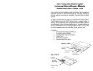
Step 4, Mounting the Receiver/AntennaReceiver/antenna position should be discussed with the vehicleowner prior to installation, since the antenna may be visible tothe vehicle’s operator.The best location for the receiver/antenna is centered high oneither the front or rear windshield. For optimal range, the antennashould be mounted vertically. It can be mounted horizontallyin relation to the windshield or under the dashboard away frommetal, but range will be diminished. Metallic window tint can alsoaffect range, so this should be a consideration when determiningthe mounting location.After determining the best mounting location, follow these steps:1. Clean the mounting area with a quality glass cleaner oralcohol to remove any dirt or residue.2. Plug the receiver/antenna cable into thereceiver/antenna.3. Mount the receiver/antenna using the supplied doublesidedtape.4. Route the receiver/antenna cable to the control moduleand plug it into the four-pin antenna connector.important! To achieve the best possible range,DO NOT leave the antenna cable bundled underthe dash. Always extend the cable full length duringinstallation, regardless of the antenna mountinglocation.28 © 2006 Directed Electronics
© 2006 Directed Electronics29
Step 5, Immobilizer Bypass ModulesMost newer vehicles have a factory engine immobilizer systemdesigned to prevent any unauthorized use of the vehicle. Theseimmobilizers will cut off power to the starter and the fuel supplypreventing a thief from starting the vehicle.There are several types of immobilizers, with the most commonbeing the resistance-based passlock/passlock 2 systems found onmost newer GM vehicles. This system can be bypassed using the20402, 29402 or 556L immobilizer bypass modules available atyour local authorized retailer or at www.directedstore.com. Themajority of transponder-based immobilizer systems can bebypassed using the 20402, 29402 or 556U immobilizer bypassmodule available at your local authorized retailer.The WHITE/BLACK wire of the 6-pin harness supplies a 400mA (-)output as soon as the control module begins the remote startprocess. This wire can be used to activate an immobilizer bypassunit.note! Any vehicle equipped with a factory immobilizermust use an immobilizer bypass module toremote start. If not used, the vehicle ignition orfuel supply circuits could lock up and require acostly trip to the dealer to reset the computer system.To determine which bypass module your vehicle requires, use thewebsite Interface Module Look-Up tool atwww.autocommand.com.30 © 2006 Directed Electronics
Step 6, ProgrammingProgramming transmittersYour system can learn up to 4 transmitters. The following procedurewill show you how to add additional transmitters or replaceold ones. Each transmitters can be programmed one button at atime or you can use an auto learn procedure that learns theintended factory configuration. Learning one button at a time isgenerally only used when using one transmitters to control twodifferent cars. Being able to program functions to different channelson each transmitters prevents multiple cars from respondingsimultaneously.1. Turn the ignition ON2. Press/release the momentary switch the same number oftimes as the desired transmitter learn Step number, andthen Press/HOLD.3. After Holding the momentary switch for 2 seconds theLED will begin to flash to indicate of the accessed transmitterlearn Step.4. Press the transmitter button that you want to controlthe function assigned to that transmitter learns Step;the Horn/Siren will emit a long chirp.note! For transmitter learn Step #1, you must pressthe “*” button on the transmitter, this will automaticallyprogram the transmitter buttons to thedefault function configuration. See the transmitterbutton auto learn chart for the assignmentfunctions.© 2006 Directed Electronics31
You can learn more than one transmitter function at a time byadvancing to another transmitter learn Step.To do this, first release the momentary SW and then press/releaseit the same number of times as the difference between the currenttransmitter learn Step and the desired transmitter learn Step, andthen press/HOLD it.example! To advance from transmitter learn Step 2to transmitter learn Step 8, release the momentarySW and then press/release it 6 times and HOLD iton the 7th press.After Holding the Valet SW for 2 seconds the LED will flash 8 timesand repeat. You can now learn a transmitter button to step 8.There are several ways to exit transmitter Learning, by TimeOut,Ignition or momentary SW Presses.1. TimeOut: If more than 15 seconds elapse betweenmomentary SW presses or transmitter signals.2. Ignition: If the Ignition is turned off at any time duringtransmitter Learning.3. Momentary SW presses: if you press/release the momentarySW more times than transmitter Learning steps inthe menu.The Horn output will pulse 5 times rapidly and the Led will turnoff to indicate exiting feature programming.32 © 2006 Directed Electronics
Transmitter Button Programming ChartStep Function Button Assignment1 Auto-Program ALL buttons to the factory default functions2 <strong>Remote</strong> Start <strong>Remote</strong> Start/Stop function3 Car Finder Carfinder function4 Headlight/Panic/Silent Headlight, Silent mode & Panic functions5 NA NA6 NA NA7 Daily Start Daily Start function8 Vacation Mode Vacation Start function9 Delete ALL TXs Removes ALL transmitters from memoryTransmitter Button Auto-Learn<strong>Remote</strong> Start/StopCarFinderHead Light control, Panic & Silent mode&&Vacation ModeDaily Start© 2006 Directed Electronics33
Programming System SettingsMany of the features and operations of this system can bechanged to suit most of today's vehicle electrical systems. Theprogramming routine and feature menus that follow will allowmaking the changes required for most vehicle installations.System programming routine:Accessing a Menu:1. Turn the ignition ON and then OFF in less than 5 seconds2. Within 3 seconds Press/Hold the Momentary Switch3. After 2 seconds the LED will flash and the Horn/Sirenwill pulse once and repeat.4. Release the Momentary Switch to access the Menu. TheLED and Horn/Siren outputs will cease.Accessing a Feature Location:1. Press and release (do not hold) the Momentary Switchthe same number of times as the feature location to beaccessed. See the Feature Chart for locations.2. After 2 seconds the LED will flash (the number of flasheswill match with the feature location) to confirm thefeature location. It will flash/pause and repeat until thefeature is changed or programming is exited.3. Press a button on the transmitter to change the featureoptiona. Option 1: Press the transmitter button assigned tothe <strong>Remote</strong> Start function (usually the button) toset factory default Option 1.34 © 2006 Directed Electronics
The LED will turn ON and the Horn/Siren will pulse once.b. Option 2-4: Press the transmitter button assigned tothe CarFinder function (usually the button) to setOptions 2-4 if available.The LED will flash and the Horn/Siren will pulse 2-4times to indicate the option and the LED continue toflash to indicate the option.Return to the beginning of the Menu:To return to the beginning of the Menu, at any time , press andhold the Momentary Switch for 2 secondsAdvance to different feature location:To advance to a new locations within the same menupress/release the Momentary Switch the same number of times asthe difference between the feature locations.example! to advance from feature location 2 to featurelocation 8 press/release (do not hold) the Momentaryswitch 6 times, after 2 seconds the LED will flash 8times to indicate the newly accessed feature location.© 2006 Directed Electronics35
Exiting Feature programming:The following will cause the system to exit programming and isindicated by 5 short chirps of the Horn/Siren output.Feature Menua. More than 15 seconds lapses between inputs byMomentary switch or transmitter buttonb. The ignition is turned onFeature Menu 1 ChartFeatureLocationFeature Name Option 1(Default)Option 2 Option 3 Option 41 Engine Monitoring No Tach Tach NA NA2 Run Time 15 min 30 min NA NA3 Crank time Normal ExtraCrank Super crank Mega crank4 Ign2 Output Ign 2 ACC 2 NA NA5 Wait-to-start Diesel Input Diesel Timer NA NAwire6 Activation Input 2 pulse 1 pulse NA NA7 Vacation Temp 0 degrees F -10 degrees F -20 degrees F NA8 Alarm Disarm 1 second 450 ms NA NA9 Horn Output Horn/Pulsing Siren/Constant NA NA10 Headlights Daytime Light your NANAway11 Start Chirp On Off NA NA12 NA NA NA NA NA13 Reset All Options Press ANY TRANSMITTER button to reset allfeatures36 © 2006 Directed Electronics
Feature Menu 1 Descriptions1. Engine Monitoring: Defines how the engine is monitored whilethe <strong>Remote</strong> Start is active.1. No Tach: The battery voltage will be used to monitor theengine while <strong>Remote</strong> Start is active.2. Tachometer: The tachometer will be used to monitorengine speed while <strong>Remote</strong> Start is active.2. Run Time1. 15 minutes: The <strong>Remote</strong> Starter will shut down after ithas been active for 15 minutes.2. 30 minutes: The <strong>Remote</strong> Starter will shut down after ithas been active for 30 minutes.3. Crank Time: Crank Time will be in effect only when EngineMonitoring is "No Tach" and affects the duration of the "Yellow"Starter Output wire.1. Normal Crank: The Starter output will be 700mS.2. Extra Crank: The Starter output will be 1 second.3. Super Crank: The Starter output will be 1.4 seconds.4. Mega Crank: The Starter output will be 2.1 seconds.4. Ignition 2 Output: This controls the output type of the highcurrent "Green" ignition 2 output wire.1. Ignition 2: Output will match the Blue Ignition 1input/output wire operation during remote start.2. Accessory 2: Output will match the White Accessory 1output wires operation.© 2006 Directed Electronics37
5. Wait-To-Start: This chooses the method of Starter output delayfor Diesel engines.1. Diesel Input wire: An input on the "Red/Blk" wire willdelay the Start output until the input ceases.2. Diesel Timer: The Starter output will be delayed until thetimer expires. The "Red/Blk" wire will be ignored.6. Activation Input: Selects the number of inputs from the transmitteror the "Red/Wht" activation input wire to activate the<strong>Remote</strong> Starter.1. 2 Pulses: Two input pulse will Start and Stop the <strong>Remote</strong>Starter2. 1 Pulse: One input pulse will Start and Stop the <strong>Remote</strong>Starter7. Vacation Temp: Selects the temperature threshold that willactivate the <strong>Remote</strong> Starter when Vacation Mode has been activated.1. 0 Degrees F2. -10 Degrees F3. -20 Degrees F8. Alarm Disarm: Selects the output duration of the "Brown/Wht"Factory Alarm Disarm wire.1. 1 second: The output will be 1 second in duration2. 450mS: The output will be 450mS in duration9. Horn Output: Selects the type of output on the "Blue" Hornoutput wire when Panic Mode is activated but does not affect theremote start/programming chirp outputs38 © 2006 Directed Electronics
1. Horn: The output will be pulsed during Panic Mode activation.2. Siren: The output will be constant during Panic Mode activation.10. Headlights: Selects the operation of the "Yellow/Brn" headlightoutput wire when an ignition input is sensed.1. Daytime Running: The output will activate 10 secondsafter an ignition input is sensed and cease output 1second after the ignition input ceases.2. LightYourWay: The output will activate for 25 secondsimmediately after the ignition input ceases.11. Start Chirps: Selects if the "Blue" Horn/Siren output wire willpulse when activating <strong>Remote</strong> Starter.1. On: The Horn output will pulse 1 time at the beginningof <strong>Remote</strong> Start2. Off: The Horn output WILL NOT pulse at the beginningof <strong>Remote</strong> Start12. NA: A feature is Not Available for this Location13. Reset All Options: Pressing a transmitter button when thisFeature Location is accessed will "Reset All Options" to theirdefault setting.© 2006 Directed Electronics39
<strong>Remote</strong> Start Diagnostics<strong>Remote</strong> Start Diagnostics:<strong>Remote</strong> Start diagnostics are an important tool that will diagnosethe status of the remote start system by letting you knowwhy it remote started, shut down or refused to start asexpected.No Start Diagnostics:If the system fails to activate <strong>Remote</strong> Start, Quick stop, DailyStart or Vacation mode as expected the parking lights will flashto indicate the reason. Consult the No Start Diagnostic Chart forthe reason.No Start Diagnostic Chart<strong>Remote</strong> StartFeatureLEDFlashesDescriptionAny 0 Indicates a loss of signal from the transmitter tothe system or a loss of power to the main unit.Daily Start 3 The unit is in the Valet Mode or Battery Voltage isbelow 11v when attempting to activate thisfeature.Vacation Mode 3 The unit is in the Valet Mode, Battery Voltage isbelow 11v, or the Brake, Hood or Ignition inputsare active<strong>Remote</strong> Start 5 The unit is in the Valet Mode, Battery Voltage isbelow 11v, or the Brake or Hood inputs are activeQuickstop 5 The unit is in the Valet Mode, Battery Voltage isbelow 11v, or the Brake or Hood inputs are active40 © 2006 Directed Electronics
Last Start Diagnostics:The system holds in memory the reason for the most recentremote start activation. This diagnostic report must be recalledusing the following operation:1. Turn the ignition ON and then OFF in less than 5 seconds2. Within 5 seconds press and release the Monetary Switch3. After 2 seconds the LED will flash/pause and repeat 5times to indicate the cause of the most recent remotestart activation.4. Count the LED flashes and consult the Last StartDiagnostic ChartLast Start Diagnostic ChartLED DescriptionFlashes1 The <strong>Remote</strong> Starter has not been activated since the main powerwas connected2 The Transmitter was used to activate the <strong>Remote</strong> starter3 The Activation Input wire was used to activate the <strong>Remote</strong> starter4 Low temperature activated the <strong>Remote</strong> Starter in Vacation Mode5 Low battery voltage activated the <strong>Remote</strong> Starter in Vacation Mode6 No Diagnostics7 Daily Start activated the <strong>Remote</strong> Starter© 2006 Directed Electronics41
Shut Down Diagnostics:The system holds in memory the reason for the most recentremote start shut down. This diagnostic report must be recalledusing the following operation:1. Step on the foot brake and hold until Step 4 has begun2. Turn the ignition ON and then OFF in less than 5 seconds3. Within 5 seconds press and release the MomentarySwitch4. After 2 seconds the LED will flash/pause and repeat 5times to indicate the cause of the most recent remotestart shut down.5. Count the LED flashes and consult the Shut DownDiagnostic ChartShutdown Diagnostic ChartLED Flashes Description1 The programmed Run Time expired2 The 'Orange' Brake Input wire was activated3 The Tachometer Input level fell below 50% of learned value4 The Transmitter was used shut down remote start5 The 'Violet' Hood Input wire was activated6 Battery voltage level fell below required level7 NA8 The Tachometer Input level was x3 times learned value for >5sec9 The "Red/Wht" activation Input was used shut down remote start42 © 2006 Directed Electronics
Testing the systemOnce steps 1 - 6 have been completed, the operation of the systemcan be tested.Ensure that the two 30-amp fuses are in the relay harness PINKwire fuse holders. Make sure that the vehicle is in park with theemergency brake on and the hood closed. Press 2 times on theremote to initiate the remote start function. The parking lightsshould flash to confirm the remote start command has beenreceived, The accessories and ignition should turn on followed bythe starter cranking and the vehicle engine running (this may takea moment to initiate). Pressing 2 times again on the remotewill shut the engine off. (See Programming System settingssection for 1 press remote start operation)This completes the testing, if all functions do not work correctlycheck your wiring against the manual and verify all connections.If you still experience problems contact Directed Technical Supportat 1-800-477-1382.© 2006 Directed Electronics43
Neutral Safety TestSome vehicles do not have an electrical neutral safety switch.Instead, a mechanical neutral safety switch that physically interruptsthe starter wire is used when the vehicle is in any drive gear.If the remote start is interfaced before this switch, it will provideprotection from starting in gear.However, some vehicles combine the column shift mechanism andthe mechanical neutral safety switch into one mechanical part. Inthese vehicles, it is impossible to interface the remote startsystem before the neutral safety switch. With this type of vehicle,if the car is left in a drive gear and the remote start system is activated,the vehicle will move and may cause damage to persons orproperty.important! This test must be performed to determineif the vehicle will start while in gear. If thevehicle attempts to start during this test youmust call Technical Support at 1-800-477-1382for assistance before using the remote start feature.Testing the Neutral Safety Switchnote! You must complete the remote start systeminstallation before doing the following test.Ensure that the remote start system is functioningnormally. This includes connecting to thebrake as a shut-down.1. Make sure there is adequate clearance to the front andrear of the vehicle because it may move slightly.2. Make sure the hood is closed and there are no remotestart shut-downs active.44 © 2006 Directed Electronics
3. Set the emergency brake.4. Turn the key to the "run" position, this will release theshifter.5. Place the shifter in the drive position.6. Place your foot directly over the brake pedal, but do notdepress it. Be ready to step on the brake if the starterengages.7. Activate the remote start system.8. If the starter does not engage, no additional safetyinterfaces are required.9. If the starter engages, immediately depress the brake toshut the remote start system down.IF THE ENGINE ATTEMPTED TO START THE VEHICLE THEN THE TESTHAS FAILEDCALL TECHNICAL SUPPORT FOR ASSISTANCE AT 1-800-477-1382warning! If the vehicle fails this test the remotestart must be disabled until the proper SafetyInterface has been installed that will keep thevehicle from starting while in gear. Failure to do somay result in property damage, injury or death.© 2006 Directed Electronics45
Troubleshooting➜The ignition comes on, but the starter will not crank.Does it start with the key in the ignition? If so, does the vehiclehave an engine immobilizer? Does it start with the brake pedaldepressed? (Make sure to disconnect the brake shutdown whenperforming this test.) If so, it may have a brake/starter interlock.Is the correct starter wire being energized? Check by energizing ityourself with a fused test lead.➜The starter cranks for 1 or 2-seconds but does not start.The wrong ignition wire is being energized or the system's ignitionand accessory wires have been connected backwards. Also, thevehicle may have two ignition circuits. Try activating the unit withthe ignition key in the "run" position. If the vehicle then runsnormally, retest your ignition system.➜The starter continues to crank after the car has started.Has the tach wire been learned? See the Tach Learning section ofthis guide. Is the tach wire receiving the correct information?Either the wrong tach wire has been used, or a bad connectionexists. Verify that all of the heavy gauge wires are plugged intothe correct tabs on the control unit. If they are incorrectlyconnected, the starter could stay engaged.➜The climate control system does not work.Either the wrong accessory wire is being energized or more thanone ignition or accessory wire must be energized in order tooperate the climate control system.➜The remote start will not activate.46 © 2006 Directed Electronics
Check to ensure that the hood is not open and that the brakepedal is not depressed. Check harnesses and connections. Makesure the harnesses are fully plugged into the remote start module.Make sure there are good connections to the vehicle wiring. Checkvoltage and fuses. Use a meter and check for voltage between theRED wire and the BLACK ground wire. If you have less than batteryvoltage, check both 30A fuses on the main power wires. Also makesure that the ground wire is going to a good paint-free chassisground.➜The remote start will activate but the starter never engages.1. Check for voltage on the YELLOW starter wire two secondsafter the remote start becomes active. If there is voltagepresent, skip to Step 4. If there is no voltage present,advance to Step 2.2. Check the 30A fuses.3. Does the vehicle have an immobilizer? Some Immobilizersystems will not allow the vehicle to crank if active.4. Check connections. The two PINK heavy gauge input wiresshould have solid connections. "T-taps", or "scotch locks" arenot recommended for any high current heavy gauge wiring.Also, if the vehicle has more than one 12-volt input wire,then connect one PINK wire to each.➜ The vehicle starts, but immediately dies.Does the vehicle have an immobilizer? The vehicle's immobilizerwill cut the fuel and/or spark during unauthorized startingattempts.➜The vehicle will start and run only for about 10 seconds.Is the remote start module programmed for voltage sense? If so,try programming the unit to tach mode.© 2006 Directed Electronics47
48 © 2006 Directed Electronics
<strong>Model</strong> <strong>28623TN</strong>➤Owner’s Guide© 2006 Directed Electronics49
Owner’s GuideNow that the installation is complete and tested, it is time tolearn about the many outstanding remote start and conveniencefeatures that are included in your system.<strong>Remote</strong> Start Features➤➤➤➤<strong>Remote</strong> Start your engine to warm or cool your vehiclebefore drivingQuickstop Mode will keep the vehicle interior warm orcool during short trips away from the vehicleDaily Start for convenient engine warm up at a specifictime the following dayVacation Mode maintains battery level when the vehicleis parked for extended periodsConvenience features➤➤➤➤➤Panic Mode feature to call for help if you are threatenedwhile in or near your vehicleCarFinder feature helps you find your vehicle in darkenedparking lotsValet Mode will temporarily defeat the remote start featuresbut leave the convenience feature availableHeadlight output can operate as daytime running lightsfor safety or light your way securely into your home orofficeSilent Mode will defeat the chirps for remote start temporarilywhen needed50 © 2006 Directed Electronics
Transmitter Button ConfigurationUsing the Auto Learn operation for programming transmitters tothis system will result in the following transmitter icon operations.controls the <strong>Remote</strong> Start/Stop functionscontrols the CarFinder featurecontrols the Headlight activation, Panic & Silent modefunctions&&activates the Vacation Mode featureactivates the Daily Start feature© 2006 Directed Electronics51
OPERATING YOUR SYSTEMS FEATURESThe <strong>Remote</strong> Start and Convenience features described in thissection follow the transmitter button assignments using the Auto-Learn step when programming a transmitter.<strong>Remote</strong> Start Features<strong>Remote</strong> Start allows you to remotely start and run your vehicle fora programmed period of time. This makes it possible to warm upthe engine, as well as adjust the interior temperature of thevehicle with the climate control system. If interior heating orcooling is desired, the climate controls must be preset, and thefan blower must be set to the desired level prior to remotestarting the vehicle.<strong>Remote</strong> Start operation is completely disabled by placing thesystem into the Valet Mode. The <strong>Remote</strong> Start, Quick Stop, DailyStart and Vacation Mode features will not operate when in theValet Mode.<strong>Remote</strong> Start the vehicle:➤ Press the button of the transmitter twice.➤➤➤The parking lights will flash once and the Horn/Sirenwill chirp once to confirm that the vehicle will attemptto start.The engine will start a few seconds after the parkinglights flash.Once started, the lights will flash and it will run for theprogrammed period of time52 © 2006 Directed Electronics
note! If the lights flash more than once and theengine does not start, refer to the No StartDiagnostics for the cause.important! Never remote start your vehicle when thekeys are in the ignition, except when activating QuickStop Mode, and never start the vehicle if it is not inPARK and the Parking brake is not set.important! It is unsafe to operate a vehicle's motorin a garage or other closed off area. Breathing theexhaust from the vehicle is hazardous to your health.Never activate the remote start in an enclosed space.When you are ready to drive the vehicle:➤➤Insert the ignition key and turn it to the ON (not theSTART) position.Press the brake pedal, the remote start will shut downand the engine will continue to runnote! If the brake pedal is pressed before the key isin the ON position, the engine will shut down.To shut down remote start:The remote start can be shut down in several ways for convenienceby the user or for safety by the shut down inputs.User remote start shut downs:➤ The transmitter button is pressed twice.➤Pulse the activation input wire twice© 2006 Directed Electronics53
➤The user steps on the brake as they begin to drive thevehicleSafety shut down inputs:While the vehicle is running during remote start operation, thesystem will monitor the vehicle and will automatically shut downthe engine if the system receives any of the following shutdowns➤➤➤➤➤The brake pedal is pressed.The hood is opened.The programmed run time has elapsed.Low battery voltageHigh or low tachometer signalQuick Stop ModeThe Quick Stop feature allows the vehicle to remain running afterthe key has been removed from the ignition. This feature is usefulfor occasions when you wish to exit the vehicle for short periodsof time, but would like to leave the motor running and the climatecontrols on.To activate Quick Stop:➤With the ignition On and the engine running, do one ofthe following:■ Press and release on the transmitter buttontwice.■■Press and release the Momentary Switch 4 timesquicklyPulse the activation input wire twice54 © 2006 Directed Electronics
➤➤➤➤The Horn/Siren will chirp once and the lights will beginflashing to indicate Quick Stop Mode is active.Turn the ignition key to the OFF position. (The enginewill stay running.)Exit the vehicle.The engine will run for the programmed run time or untila shut down input is activated.Daily Startnote! Quick Stop mode will not activate if thebrake pedal is depressed.The Daily Start feature will automatically start the engine 24 hoursafter it has been activated. This is convenient if you leave yourhouse for work at the same time everyday. Simply activate asdescribed 24 hours before you wish for the engine to start.To activate Daily Start:➤ Press and hold the & buttons on your transmitterfor more than 3 seconds➤➤The parking lights will flash 4 times and the Horn/sirenwill chirp once to confirm Daily Start is activated.Your vehicles engine will <strong>Remote</strong> Start in 24 hours.important! When Daily Start is active ONLY park youcar in a well ventilated areas.© 2006 Directed Electronics55
To de-activate Daily Start:➤ Press and hold the & buttons on your transmitterfor more than 3 seconds➤➤Activate Vacation ModeThe parking lights will flash 4 times to confirm DailyStart has been de-activated. (The Horn/siren will notchirp)Vacation ModeVacation mode is a valuable feature designed to maintain normaloperating conditions when the vehicle is parked for extendedperiods. Vacation mode will monitor and automatically start theengine any time the system detects extremely low battery voltageor temperatures (See Programming Section for available lowtemperature settings).To activate Vacation Mode:➤ Press and hold the & buttons on your transmitterfor more than 3 seconds➤➤➤➤The parking lights will flash 5 times and the Horn/Sirenwill chirp once to confirm Vacation Mode is activated.Your vehicles battery level and interior temperature willbe monitored and the engine will automatically start upto 8 times.Temperature: the system will check the interior temperatureand start if required every three hoursBattery level: the system will start the engine immediatelywhen the battery level drops below 11.5 volts.56 © 2006 Directed Electronics
important! When Vacation mode is activated ONLYpark you car in a well ventilated areas.To de-activate Vacation Mode:➤ Press and hold the & buttons on your transmitterfor more than 3 seconds➤➤➤Activate Daily StartActivate the Ignition, Hood or Brake inputs at any timeThe parking lights will flash 5 times to confirm Vacationmode has been de-activated. (The Horn/siren will notchirp)Panic ModeThis system includes a Panic Mode operation that will alert otheraround you if you are threatened while in or near your vehicle. Dueto state laws the Panic Mode is defeated when the ignition is on.To active Panic Mode:➤ Press and hold the button on the transmitter for 6seconds➤The Horn/Siren output and light flash will activate for45 secondsTo de-active Panic Mode:➤ Press and release the button on the transmitter© 2006 Directed Electronics57
Valet ModeValet Mode will defeat the remote start operations while leavingall convenience features available such as Panic, Trunk Pop, andCarfinder.To enter Valet Mode:➤➤➤➤Press and hold the Momentary SwitchTurn the ignition On and Off in less than 5 secondsContinue to hold the Momentary SwitchAfter 2 seconds the LED will turn on solid, Valet Mode isenteredTo exit Valet Mode:note! The LED will stay on only when the ignitionis off. After the ignition has been off for 24 hoursthe LED will turn off until the ignition is cycledon/off.➤➤➤➤Press and hold the Momentary SwitchTurn the ignition On and Off in less than 5 secondsContinue to hold the Momentary SwitchAfter 2 seconds the LED will turn off, Valet Mode isexited58 © 2006 Directed Electronics
Convenience FeaturesCarfinder FeatureThis feature allows you easily locate you vehicle in large and darkenedparking areas by pulsing the lights and Horn/Siren outputs.To activate Carfinder:➤ Press and release the button on the transmitter➤The headlight output, parking light output and theHorn/siren output will pulse onceSilent ModeSilent Mode allows you to temporarily delete the Horn/Sirenoutput when activating remote start.To use Silent Mode:➤ Press and release quickly the button on the transmitter➤After 1 second activate remote start, the Horn/Siren willbe defeated.note! 10 seconds after step 1 the Horn/Siren outputwill be re-activated. If Silent Mode is your preferrednormal operation the Horn/Siren output can be programmedoff in the feature menus. Then using SilentMode will temporarily turn on the Horn/Siren output.Headlight ControlThis feature allows you to toggle the headlight output on and offanytime the ignition is off.To activate the Headlights:© 2006 Directed Electronics59
➤ Press and hold for 3 seconds the button on thetransmitter and then release it.➤The headlight output toggle on/off according to itspresent statenote! The headlight output timer is 25 secondsand is controlled by the ignition input accordingto the programmed setting.60 © 2006 Directed Electronics
Glossary of termsControl Module: The “brain” of your system. Usually hidden underthe dash area of the vehicle. It houses the microprocessor thatmonitors your vehicle and controls all system functions.FAD: Factory Alarm Disarm. Some vehicles with a factory alarmrequire the alarm to be disarmed before remote starting.RAP: Retained Accessory Power. After the vehicle is started andthen shut down, the power to the radio remains on (retained) untila vehicle door is opened.Transmitter: A hand-held, remote control which operates the variousfunctions of your system.© 2006 Directed Electronics61
Notes_____________________________________________________________________________________________________________________________________________________________________________________________________________________________________________________________________________________________________________________________________________________________________________________________________________________________________________________________________________________________________________________________________________________________________________________________________________________________________________________________________________________________________________________________________________________________________________________________________________________________________________________________________________________________________________________________________________________________________________________________________________________________________________________________________62 © 2006 Directed Electronics
Cut along dotted line and fold for a quick and easy reference to keep in your purse or wallet.✂✂QUICK REFERENCE GUIDE:Convenience Features■ Activate Panic Mode: Press and hold the button for 6seconds■ Activate CarFinder: Press/release quickly thebutton■ Activate Headlights: Press and hold for 3 seconds and thenrelease the button<strong>Remote</strong> Start the engine■ To Start: Press the button twice. The engine will start andthe parking lights will flash to confirm start.■ To Stop: Perform the same steps as above to shut downremote start.Quick stop Mode■ To activate: Press the button twice with ignition on andthe engine running or press/release the Momentary Switch 4times■ To de-activate: Press the button twice or step on thebrakeDaily Start■ To activate: Press the and buttons for three seconds.The lights will flash 4times and the Horn/Siren will chirp once to confirm.■ To de-activate: Perform the same step to exit, the parkinglights will flash 4 times, the Horn/siren will not pulseVacation mode■ To activate: Press the and buttons for three seconds.The lights willflash 5 times and the Horn/Siren will chirp once to confirm.■ To de-activate: Perform the same step to exit, the parkinglights will flash 5 times, the Horn/siren will not pulse© 2006 Directed Electronics63
The company behind this system is Directed ElectronicsSince its inception, Directed Electronics has had one purpose, to provide consumers withthe finest vehicle security and car stereo products and accessories available. The recipient ofnearly 100 patents and Innovations Awards in the field of advanced electronictechnology, DIRECTED is ISO 9001 registered.Quality Directed Electronics products are sold and serviced throughout North Americaand around the world.Call (800) 274-0200 for more information about our products and services.Directed Electronics is committed to delivering world class quality productsand services that excite and delight our customers.Directed ElectronicsVista, CA 92081www.directed.com© 2006 Directed Electronics—All rights reservedN<strong>28623TN</strong> 06-06