AC-DC Single Output Power Module - TDK-Lambda
AC-DC Single Output Power Module - TDK-Lambda
AC-DC Single Output Power Module - TDK-Lambda
Create successful ePaper yourself
Turn your PDF publications into a flip-book with our unique Google optimized e-Paper software.
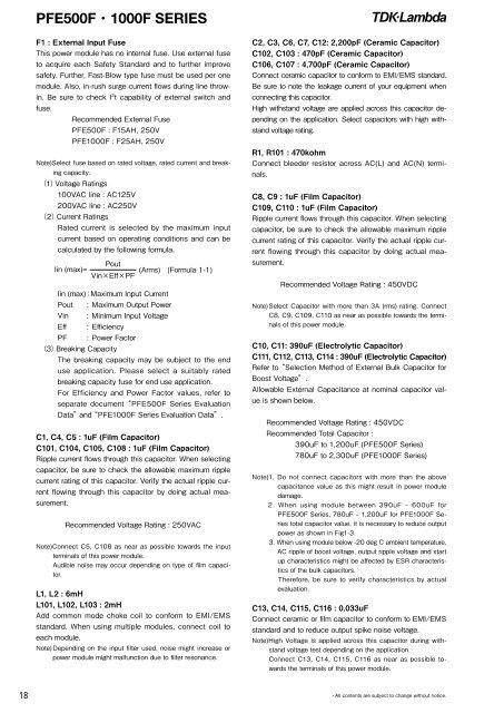
PFE500F・1000F SERIESF1 : External Input FuseThis power module has no internal fuse. Use external fuseto acquire each Safety Standard and to further improvesafety. Further, Fast-Blow type fuse must be used per onemodule. Also, in-rush surge current flows during line throwin.Be sure to check I 2 t capability of external switch andfuse.Recommended External FusePFE500F : F15AH, 250VPFE1000F : F25AH, 250VNote)Select fuse based on rated voltage, rated current and breakingcapacity.(1)Voltage Ratings100V<strong>AC</strong> line : <strong>AC</strong>125V200V<strong>AC</strong> line : <strong>AC</strong>250V(2)Current RatingsRated current is selected by the maximum inputcurrent based on operating conditions and can becalculated by the following formula.PoutIin (max)=(Arms) (Formula 1-1)Vin×Eff×PFIin (max):Maximum Input CurrentPout : Maximum <strong>Output</strong> <strong>Power</strong>Vin : Minimum Input VoltageEff : EfficiencyPF : <strong>Power</strong> Factor(3)Breaking CapacityThe breaking capacity may be subject to the enduse application. Please select a suitably ratedbreaking capacity fuse for end use application.For Efficiency and <strong>Power</strong> Factor values, refer toseparate document “PFE500F Series EvaluationData”and “PFE1000F Series Evaluation Data”.C1, C4, C5 : 1uF (Film Capacitor)C101, C104, C105, C108 : 1uF (Film Capacitor)Ripple current flows through this capacitor. When selectingcapacitor, be sure to check the allowable maximum ripplecurrent rating of this capacitor. Verify the actual ripple currentflowing through this capacitor by doing actual measurement.Recommended Voltage Rating : 250V<strong>AC</strong>Note)Connect C5, C108 as near as possible towards the inputterminals of this power module.Audible noise may occur depending on type of film capacitor.L1, L2 : 6mHL101, L102, L103 : 2mHAdd common mode choke coil to conform to EMI/EMSstandard. When using multiple modules, connect coil toeach module.Note) Depending on the input filter used, noise might increase orpower module might malfunction due to filter resonance.C2, C3, C6, C7, C12: 2,200pF (Ceramic Capacitor)C102, C103 : 470pF (Ceramic Capacitor)C106, C107 : 4,700pF (Ceramic Capacitor)Connect ceramic capacitor to conform to EMI/EMS standard.Be sure to note the leakage current of your equipment whenconnecting this capacitor.High withstand voltage are applied across this capacitor dependingon the application. Select capacitors with high withstandvoltage rating.R1, R101 : 470kohmConnect bleeder resistor across <strong>AC</strong>(L) and <strong>AC</strong>(N) terminals.C8, C9 : 1uF (Film Capacitor)C109, C110 : 1uF (Film Capacitor)Ripple current flows through this capacitor. When selectingcapacitor, be sure to check the allowable maximum ripplecurrent rating of this capacitor. Verify the actual ripple currentflowing through this capacitor by doing actual measurement.Recommended Voltage Rating : 450V<strong>DC</strong>Note) Select Capacitor with more than 3A (rms) rating. ConnectC8, C9, C109, C110 as near as possible towards the terminalsof this power module.C10, C11: 390uF (Electrolytic Capacitor)C111, C112, C113, C114 : 390uF (Electrolytic Capacitor)Refer to “Selection Method of External Bulk Capacitor forBoost Voltage”.Allowable External Capacitance at nominal capacitor valueis shown below.Recommended Voltage Rating : 450V<strong>DC</strong>Recommended Total Capacitor :390uF to 1,200uF (PFE500F Series)780uF to 2,300uF (PFE1000F Series)Note)1. Do not connect capacitors with more than the abovecapacitance value as this might result in power moduledamage.2. When using module between 390uF – 600uF forPFE500F Series, 780uF – 1,200uF for PFE1000F Seriestotal capacitor value, it is necessary to reduce outputpower as shown in Fig1-3.3. When using module below -20 deg C ambient temperature,<strong>AC</strong> ripple of boost voltage, output ripple voltage and startup characteristics might be affected by ESR characteristicsof the bulk capacitors.Therefore, be sure to verify characteristics by actualevaluation.C13, C14, C115, C116 : 0.033uFConnect ceramic or film capacitor to conform to EMI/EMSstandard and to reduce output spike noise voltage.Note)High Voltage is applied across this capacitor during withstandvoltage test depending on the application.Connect C13, C14, C115, C116 as near as possible towardsthe terminals of this power module.18・All contents are subject to change without notice.


