AC-DC Single Output Power Module - TDK-Lambda
AC-DC Single Output Power Module - TDK-Lambda
AC-DC Single Output Power Module - TDK-Lambda

Create successful ePaper yourself
Turn your PDF publications into a flip-book with our unique Google optimized e-Paper software.
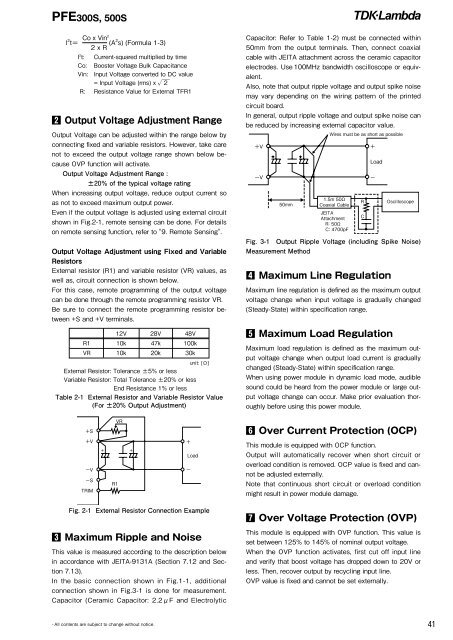
PFE300S, 500Sl 2 t= Co x Vin2 (A 2 s) (Formula 1-3)2 x RI 2 t: Current-squared multiplied by timeCo: Booster Voltage Bulk CapacitanceVin: Input Voltage converted to <strong>DC</strong> value= Input Voltage (rms) x √ ̄2R: Resistance Value for External TFR12 <strong>Output</strong> Voltage Adjustment Range<strong>Output</strong> Voltage can be adjusted within the range below byconnecting fixed and variable resistors. However, take carenot to exceed the output voltage range shown below becauseOVP function will activate.<strong>Output</strong> Voltage Adjustment Range :±20% of the typical voltage ratingWhen increasing output voltage, reduce output current soas not to exceed maximum output power.Even if the output voltage is adjusted using external circuitshown in Fig.2-1, remote sensing can be done. For detailson remote sensing function, refer to "9. Remote Sensing".<strong>Output</strong> Voltage Adjustment using Fixed and VariableResistorsExternal resistor (R1) and variable resistor (VR) values, aswell as, circuit connection is shown below.For this case, remote programming of the output voltagecan be done through the remote programming resistor VR.Be sure to connect the remote programming resistor between+S and +V terminals.12V 28V 48VR1 10k 47k 100kVR 10k 20k 30kunit: [Ω]External Resistor: Tolerance ±5% or lessVariable Resistor: Total Tolerance ±20% or lessEnd Resistance 1% or lessTable 2-1 External Resistor and Variable Resistor Value(For ±20% <strong>Output</strong> Adjustment)Capacitor: Refer to Table 1-2) must be connected within50mm from the output terminals. Then, connect coaxialcable with JEITA attachment across the ceramic capacitorelectrodes. Use 100MHz bandwidth oscilloscope or equivalent.Also, note that output ripple voltage and output spike noisemay vary depending on the wiring pattern of the printedcircuit board.In general, output ripple voltage and output spike noise canbe reduced by increasing external capacitor value.Fig. 3-1 <strong>Output</strong> Ripple Voltage (including Spike Noise)Measurement Method4 Maximum Line RegulationMaximum line regulation is defined as the maximum outputvoltage change when input voltage is gradually changed(Steady-State) within specification range.5 Maximum Load RegulationMaximum load regulation is defined as the maximum outputvoltage change when output load current is graduallychanged (Steady-State) within specification range.When using power module in dynamic load mode, audiblesound could be heard from the power module or large outputvoltage change can occur. Make prior evaluation thoroughlybefore using this power module.6 Over Current Protection (OCP)This module is equipped with OCP function.<strong>Output</strong> will automatically recover when short circuit oroverload condition is removed. OCP value is fixed and cannotbe adjusted externally.Note that continuous short circuit or overload conditionmight result in power module damage.Fig. 2-1 External Resistor Connection Example3 Maximum Ripple and NoiseThis value is measured according to the description belowin accordance with JEITA-9131A (Section 7.12 and Section7.13).In the basic connection shown in Fig.1-1, additionalconnection shown in Fig.3-1 is done for measurement.Capacitor (Ceramic Capacitor: 2.2μF and Electrolytic7 Over Voltage Protection (OVP)This module is equipped with OVP function. This value isset between 125% to 145% of nominal output voltage.When the OVP function activates, first cut off input lineand verify that boost voltage has dropped down to 20V orless. Then, recover output by recycling input line.OVP value is fixed and cannot be set externally.・All contents are subject to change without notice.41