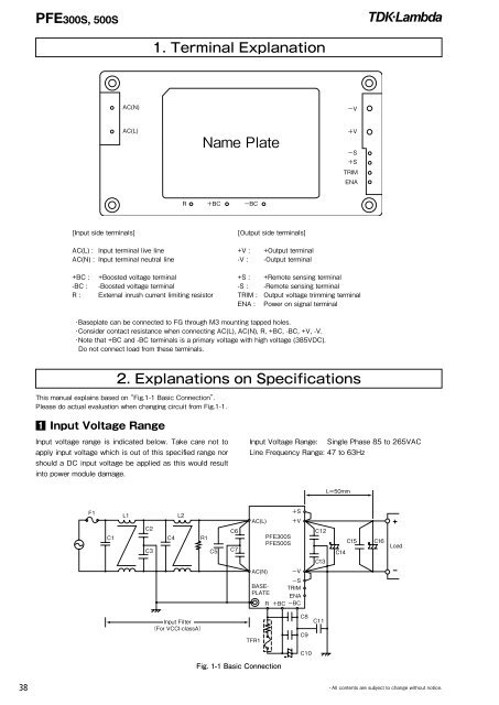
PFE300S, 500S1. Terminal Explanation[Input side terminals]<strong>AC</strong>(L) : Input terminal live line<strong>AC</strong>(N) : Input terminal neutral line[<strong>Output</strong> side terminals]+V : +<strong>Output</strong> terminal-V : -<strong>Output</strong> terminal+BC :-BC :R :+Boosted voltage terminal-Boosted voltage terminalExternal inrush current limiting resistor+S : +Remote sensing terminal-S : -Remote sensing terminalTRIM : <strong>Output</strong> voltage trimming terminalENA : <strong>Power</strong> on signal terminal・Baseplate can be connected to FG through M3 mounting tapped holes.・Consider contact resistance when connecting <strong>AC</strong>(L), <strong>AC</strong>(N), R, +BC, -BC, +V, -V.・Note that +BC and -BC terminals is a primary voltage with high voltage (385V<strong>DC</strong>).Do not connect load from these terminals.2. Explanations on SpecificationsThis manual explains based on “Fig.1-1 Basic Connection”.Please do actual evaluation when changing circuit from Fig.1-1.1 Input Voltage RangeInput voltage range is indicated below. Take care not toapply input voltage which is out of this specified range norshould a <strong>DC</strong> input voltage be applied as this would resultinto power module damage.Input Voltage Range: <strong>Single</strong> Phase 85 to 265V<strong>AC</strong>Line Frequency Range: 47 to 63Hz Fig. 1-1 Basic Connection38 ・All contents are subject to change without notice.
PFE300S, 500SF1: External Input FuseThis power module has no internal fuse. Use external fuseto acquire each safety standard and to further improvesafety. Further, Fast-Blow type fuse must be used per onemodule. Also, in-rush surge current flows during line throwin.Be sure to check I 2 t rating of external switch and externalfuse.Recommended External Fuse: 15ASelect fuse based on rated voltage, rated current andsurge current capability.(1)Voltage Ratings100V<strong>AC</strong> line: <strong>AC</strong>125V200V<strong>AC</strong> line: <strong>AC</strong>250V(2)Current RatingsRated current is determined by the maximum inputcurrent based on operating conditions and can be calculatedby the following formula.lin(max) =PoutVin x Eff x PF(Arms) (Formula 1-1)Iin (max): Maximum Input CurrentPout: Maximum <strong>Output</strong> <strong>Power</strong>Vin: Minimum Input VoltageEff: EfficiencyPF: <strong>Power</strong> FactorFor efficiency and power factor values, refer to separate"Evaluation Data of each product".C1, C4, C5: 1uF (Film Capacitor)Ripple current flows through this capacitor. When selectingcapacitor, be sure to check the allowable maximum ripplecurrent rating of this capacitor. Verify the actual ripplecurrent flowing through this capacitor by doing actual measurement.Recommended Voltage Rating: 250V<strong>AC</strong>Note)Connect C5 as near as possible towards the input terminalsof this power module.L1, L2: 6mHAdd common mode choke coil as EMI/EMS counter-measure.When using multiple modules, connect coil to eachmodule.Note)Depending on the input filter used, noise might increaseor power module might malfunction due to filter resonance.C2, C3: 4,700pF (Ceramic Capacitor)Add ceramic capacitor as EMI/EMS countermeasure. Besure to consider leakage current of your equipment whenadding this capacitor.High withstand voltage are applied across this capacitordepending on the application. Select capacitors with highwithstand voltage rating.C6, C7: 1000pF (Ceramic Capacitor)Add ceramic capacitor as EMI/EMS countermeasure. Besure to consider leakage current of your equipment whenadding this capacitor.High withstand voltage are applied across this capacitorduring withstand voltage test depending on the application.Select capacitors with high withstand voltage rating.Also, connect C6, C7 as close as possible to the terminals.C8, C9: 1uF (Film Capacitor)Ripple current flows through this capacitor. When selectingcapacitor, be sure to check the allowable maximum ripplecurrent rating of this capacitor. Verify the actual ripplecurrent flowing through this capacitor by doing actual measurement.Recommended Voltage Rating : 450V<strong>DC</strong>Note)Select Capacitor with more than 3A (rms) rating. ConnectC8, C9 as near as possible towards the output terminalsof this power module.C10: Electrolytic CapacitorPFE300S: 470μF×1PFE500S: 390μF×2 pcs in parallelRefer to "Selection Method of External Bulk Capacitor forBoost Voltage" below.Allowable External Capacitance at nominal capacitor valueis shown below.Recommended Voltage Rating: 450V<strong>DC</strong>Recommended Total Capacitor: 390uF to 1,200uFNote)1. Do not connect capacitors with more than the abovecapacitance value as this would result into powermodule damage.2. When using module below -20℃ ambient temperature,<strong>AC</strong> ripple of boost voltage, output ripple voltage andstand up characteristics might be affected by ESRcharacteristics of the bulk capacitor.Therefore, be sure to verify characteristics by actualevaluation.C11: 1000pF (Ceramic Capacitor)Add ceramic capacitor as EMI/EMS countermeasure.High withstand voltage are applied across this capacitorduring withstand voltage test depending on the application.Select capacitors with high withstand voltage rating.Also, connect C11 as close as possible to the terminals.C12, C13: 0.033uFConnect ceramic or film capacitor as EMI/EMS countermeasureand to reduce spike noise.Note)High Voltage is applied across this capacitor duringwithstand voltage test depending on the application.Connect C12, C13 as near as possible towards the outputterminals of this power module.R1: 470kΩConnect bleeder resistor across <strong>AC</strong>(L) and <strong>AC</strong>(N) terminals.・All contents are subject to change without notice.39