

308877B Quick Fan Adjust Kit - Graco Inc.
308877B Quick Fan Adjust Kit - Graco Inc.
308877B Quick Fan Adjust Kit - Graco Inc.

You also want an ePaper? Increase the reach of your titles
YUMPU automatically turns print PDFs into web optimized ePapers that Google loves.
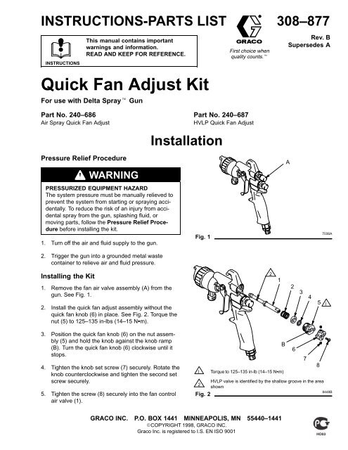
INSTRUCTIONS-PARTS LISTINSTRUCTIONSThis manual contains importantwarnings and information.READ AND KEEP FOR REFERENCE.<strong>Quick</strong> <strong>Fan</strong> <strong>Adjust</strong> <strong>Kit</strong>For use with Delta Spray GunFirst choice whenquality counts.308–877Rev. BSupersedes APart No. 240–686Air Spray <strong>Quick</strong> <strong>Fan</strong> <strong>Adjust</strong>Pressure Relief ProcedureWARNINGPRESSURIZED EQUIPMENT HAZARDThe system pressure must be manually relieved toprevent the system from starting or spraying accidentally.To reduce the risk of an injury from accidentalspray from the gun, splashing fluid, ormoving parts, follow the Pressure Relief Procedurebefore installing the kit.1. Turn off the air and fluid supply to the gun.2. Trigger the gun into a grounded metal wastecontainer to relieve air and fluid pressure.InstallationPart No. 240–687HVLP <strong>Quick</strong> <strong>Fan</strong> <strong>Adjust</strong>Fig. 1A7036AInstalling the <strong>Kit</strong>1. Remove the fan air valve assembly (A) from thegun. See Fig. 1.2. Install the quick fan adjust assembly without thequick fan knob (6) in place. See Fig. 2. Torque thenut (5) to 125–135 in-lbs (14–15 Nm).21234513. Position the quick fan knob (6) on the nut assembly(5) and hold the knob against the knob ramp(B). Turn the quick fan knob (6) clockwise until itstops.4. Tighten the knob set screw (7) securely. Rotate theknob counterclockwise and tighten the second setscrew securely.5. Tighten the screw (8) securely into the fan controlair valve (1).B6781 Torque to 125–135 in-lb (14–15 Nm)HVLP valve is identified by the shallow groove in the area2shownFig. 28448BGRACO INC. P.O. BOX 1441 MINNEAPOLIS, MN 55440–1441COPYRIGHT 1998, GRACO INC.<strong>Graco</strong> <strong>Inc</strong>. is registered to I.S. EN ISO 9001
OperationRotate the quick fan knob (6) clockwise to reduce thefan pattern size and counterclockwise to increase thefan pattern size.2123451PartsAir Spray <strong>Quick</strong> <strong>Fan</strong> <strong>Adjust</strong>Part No. 240–686Ref. Part No. Description Qty.No.1 193–477 VALVE, fan control, air 1spray2 114–070 SPRING, compression 13 193–479 WASHER 14 110–453 PACKING, u-cup, nut 15 240–676 NUT ASSEMBLY 16 193–475 KNOB, quick fan 17 111–274 SCREW, set, socket head 28 103–180 SCREW, truss head 1HVLP <strong>Quick</strong> <strong>Fan</strong> <strong>Adjust</strong>Part No. 240–6871 Torque to 125–135 in-lb (14–15 Nm)2HVLP valve is identified by the shallow groove in the areashown6788448BRef. Part No. Description Qty.No.1 193–478 VALVE, fan control, HVLP 12 114–070 SPRING, compression 13 193–479 WASHER 14 110–453 PACKING, u-cup, nut 15 240–676 NUT ASSEMBLY 16 193–475 KNOB, quick fan 17 111–274 SCREW, set, socket head 28 103–180 SCREW, truss head 1Manual Change SummaryThe manual was revised to change 102–387 set screw to 111–274 and to add screw 103–180.<strong>Graco</strong> Phone NumberTO PLACE AN ORDER, contact your <strong>Graco</strong> distributor, or call this number to identify the distributor closest to you:1–800–367–4023 Toll Free.All written and visual data contained in this document reflects the latest product information available at the time of publication.<strong>Graco</strong> reserves the right to make changes at any time without notice.Sales Offices: Minneapolis, DetroitForeign Offices: Belgium, England, Korea, France, Germany, Hong Kong, JapanGRACO INC. P.O. BOX 1441 MINNEAPOLIS, MN 55440–1441http://www.graco.comPRINTED IN USA 308–877 June 1998 Revised July 1998


