

310526U, Instructions-Parts List for Ram Supply Unit ... - Graco Inc.
310526U, Instructions-Parts List for Ram Supply Unit ... - Graco Inc.
310526U, Instructions-Parts List for Ram Supply Unit ... - Graco Inc.

You also want an ePaper? Increase the reach of your titles
YUMPU automatically turns print PDFs into web optimized ePapers that Google loves.
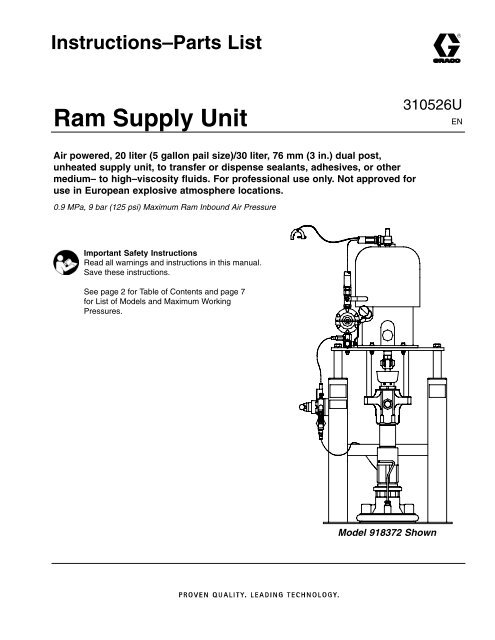
<strong>Instructions</strong>–<strong>Parts</strong> <strong>List</strong><strong>Ram</strong> <strong>Supply</strong> <strong>Unit</strong><strong>310526U</strong>ENAir powered, 20 liter (5 gallon pail size)/30 liter, 76 mm (3 in.) dual post,unheated supply unit, to transfer or dispense sealants, adhesives, or othermedium– to high–viscosity fluids. For professional use only. Not approved <strong>for</strong>use in European explosive atmosphere locations.0.9 MPa, 9 bar (125 psi) Maximum <strong>Ram</strong> Inbound Air PressureImportant Safety <strong>Instructions</strong>Read all warnings and instructions in this manual.Save these instructions.See page 2 <strong>for</strong> Table of Contents and page 7<strong>for</strong> <strong>List</strong> of Models and Maximum WorkingPressures.Model 918372 Shown
Table Of ContentsSymbols . . . . . . . . . . . . . . . . . . . . . . . . . . . . . . . . . . . . . . 3Warnings . . . . . . . . . . . . . . . . . . . . . . . . . . . . . . . . . . . . . . 3<strong>List</strong> of Models . . . . . . . . . . . . . . . . . . . . . . . . . . . . . . . . . . 6Pump Selection Chart . . . . . . . . . . . . . . . . . . . . . . . . . . . 7Typical Installation . . . . . . . . . . . . . . . . . . . . . . . . . . . . . . 8Installation . . . . . . . . . . . . . . . . . . . . . . . . . . . . . . . . . . . . 11Operation . . . . . . . . . . . . . . . . . . . . . . . . . . . . . . . . . . . . 13Troubleshooting Chart . . . . . . . . . . . . . . . . . . . . . . . . . 16Service . . . . . . . . . . . . . . . . . . . . . . . . . . . . . . . . . . . . . . 17<strong>Parts</strong> . . . . . . . . . . . . . . . . . . . . . . . . . . . . . . . . . . . . . . . . 18Accessories . . . . . . . . . . . . . . . . . . . . . . . . . . . . . . . . . . 63Dimensions . . . . . . . . . . . . . . . . . . . . . . . . . . . . . . . . . . . 64<strong>Ram</strong> <strong>Supply</strong> <strong>Unit</strong> Technical Data . . . . . . . . . . . . . . . . . 65<strong>Graco</strong> Standard Warranty . . . . . . . . . . . . . . . . . . . . . . 66<strong>Graco</strong> In<strong>for</strong>mation . . . . . . . . . . . . . . . . . . . . . . . . . . . . . 662310526
SymbolsWarning SymbolWARNINGThis symbol alerts you to the possibility of seriousinjury or death if you do not follow the correspondinginstructions.Caution SymbolCAUTIONThis symbol alerts you to the possibility of damage toor destruction of equipment if you do not follow thecorresponding instructions.INSTRUCTIONSEQUIPMENT MISUSE HAZARDWARNINGEquipment misuse can cause the equipment to rupture, malfunction, or start unexpectedly andresult in serious injury.This equipment is <strong>for</strong> professional use only.Read all instruction manuals, warnings, tags, and labels be<strong>for</strong>e operating the equipment.Use the equipment only <strong>for</strong> its intended purpose. If you are uncertain about usage, call yourdistributor.Do not alter or modify this equipment. Use only genuine <strong>Graco</strong> parts and accessories.Check the equipment daily. Repair or replace worn or damaged parts immediately.Do not exceed 9 MPa, 9 bar (125 psi) maximum inbound air pressure to the ram.Never exceed the recommended working pressure or the maximum air inlet pressure stated onyour pump or in the Pump Chart on page 7.Be sure that all spray/dispensing equipment and accessories are rated to withstand the maximumworking pressure of the pump. Do not exceed the maximum working pressure of anycomponent or accessory used in the system.Route the hoses away from the traffic areas, sharp edges, moving parts, and hot surfaces. Donot expose <strong>Graco</strong> hoses to temperatures above 82 C (180 F) or below -40 C (-40 F).Do not kink or overbend hoses or use hoses to pull the equipment.Do not touch the metal heat sink when the surface is hot.Use fluids that are compatible with the equipment wetted parts. See the Technical Data sectionsof all the equipment manuals. Read the fluid manufacturer’s warnings be<strong>for</strong>e using fluid orsolvent in this pump.Always wear protective eyewear, gloves, clothing, and respirator as recommended by the fluidand solvent manufacturers.Wear hearing protection when operating this equipment.Comply with all applicable local, state and national fire, electrical and other safety regulations.310526 3
SKIN INJECTION HAZARDWARNINGSpray from the spray gun, hose leaks, or ruptured components can inject fluid into your body andcause extremely serious injury, including the need <strong>for</strong> amputation. Splashing fluid in the eyes or onthe skin can also cause serious injury.Fluid injected into the skin might look like just a cut, but it is a serious injury. Get immediatesurgical treatment.Do not point the gun/valve at anyone or at any part of the body.Do not put your hand or fingers over the spray tip/nozzle.Do not stop or deflect fluid leaks with your hand, body, glove, or rag.Always have the trigger guard on the gun when dispensing.Check the gun diffuser operation weekly. Refer to the gun manual.Be sure the gun/valve trigger safety operates be<strong>for</strong>e dispensing.Lock the gun/valve trigger safety when you stop dispensing.Follow the Pressure Relief Procedure on page 13 if the nozzle clogs, and be<strong>for</strong>e cleaning,checking or servicing the equipment.Tighten all fluid connections be<strong>for</strong>e operating the equipment.Check the hoses, tubes, and couplings daily. Replace worn, damaged, or loose parts immediately.Do not repair high pressure couplings; you must replace the entire hose.Fluid hoses must have spring guards on both ends, to help protect them from rupture caused bykinks or bends near the couplings.FIRE AND EXPLOSION HAZARDImproper grounding, poor air ventilation, open flames or sparks can cause a hazardous conditionand result in fire or explosion and serious injury. Ground the equipment and the object being sprayed. Refer to Ground the System on page 11.If there is any static sparking while using the equipment, stop dispensing immediately. Identifyand correct the problem.Provide fresh air ventilation to avoid the buildup of flammable fumes from solvent or material.Do not smoke in the dispense area.Extinguish all open flames or pilot lights in the dispense area.Do not turn on or off any light switch in the dispense area.Keep the dispense area free of debris, including solvent, rags, and gasoline.Keep a fire extinguisher in the work area.4310526
MOVING PARTS HAZARDWARNINGMoving parts, such as the ram follower plate/pump inlet can pinch fingers.Keep clear of all moving parts when starting or operating the equipment.Keep hands and fingers away from the priming piston during operation and whenever the pumpis charged with air.Keep clear of the follower plate, pump fluid inlet, and lip of the fluid container when raising orlowering the ram.Be<strong>for</strong>e checking or servicing the ram or pump, follow the Pressure Relief Procedure onpage 13.TOXIC FLUID HAZARDHazardous fluid or toxic fumes can cause serious injury or death if splashed in the eyes or on theskin, inhaled, or swallowed.Know the specific hazards of the fluid you are using.Store hazardous fluid in an approved container. Dispose of hazardous fluid according to alllocal, state and national guidelines.Always wear protective eyewear, gloves, clothing and respirator as recommended by the fluidand solvent manufacturer.310526 5
<strong>List</strong> of Models<strong>Ram</strong> <strong>Supply</strong><strong>Unit</strong> Part No.Pail Size76 mm (3 in.) <strong>Ram</strong>Follower WiperPumpPart No.<strong>Parts</strong>Page30 liter 5 gallon PVC Buna–N241082** 240945 18241083** 222813 20241084** 222833 22241630** 245173 24570153** * 26918371 237261 28918372 240945 30253293 240945 30253375 253376 32918378 237707 34918379 237707 35918380 237708 36918386 222813 38970018 240945 40234977 240945 40970031 240945 42970247 240945 44970248 240945 46970249 222813 48970250 222833 50C59774** 222832 52C59777** 245173 54* Pump and air motor not available as an assembly. Refer to parts page.** These units are not CE certified. This unit includes heated plate with silicone wiper.6310526
Pump ChartPumpPart No.Ratio Pump Model DisplacementPumpMaximum FluidPressureMaximum PumpAir InputModel CS SST MPa bar psi MPa bar psiPumpManualNo.*222813 55:1 BulldogQuiet CM450 34 341 4950 0.6 6 90 308017222832 20:1 King Quiet DF2400 14 138 2000 0.7 7 100 308151222833 20:1 King DF2400 12 124 1800 0.6 6 90 308151237261 31:1 Bulldog CM800 21 214 3100 0.7 7 100 308351237707 50:1 King CM1000 31 310 4500 0.6 6 90 308355237708 50:1 King CM1000 31 310 4500 0.6 6 90 308356240945 65:1 King Quiet CM800 34 345 5000 0.6 6 90 308351245173 56:1 King Quiet DF900 39 386 5600 0.7 7 100 308354CS = carbon steelSST = stainless steel*See the pump manual <strong>for</strong> additional specifications and parts in<strong>for</strong>mation.310526 7
Typical InstallationABCDEFGHIJKAir Line FilterAccessory Bleed-Type Master Air Valve(required)Pump Bleed-Type Master Air Valve (required)Pump Air RegulatorMain Air Line <strong>Supply</strong>Air ManifoldFollower Plate Blowoff Button<strong>Ram</strong> Air <strong>Supply</strong> HoseAir Line LubricatorFluid Drain Valve (required)Fluid RegulatorL Applicator Gun or ValveM Gun SwivelN Mounting Plate1 Wiper Seal2 Pump Assembly3 <strong>Ram</strong> Hand Valve4 <strong>Ram</strong> Module5 Follower Gasket6 Follower Assembly7 Grounding Wire (required; see page 11 <strong>for</strong>installation instructions)8 Bleed Handle918372 shown with 241086 and Follower Kit 91840872CDFNIA B EHK3GJ561ML48Fig. 18817A8310526
Typical InstallationThe typical installation discussed below is only a guide<strong>for</strong> selecting and installing system components andaccessories. Contact your <strong>Graco</strong> representative or<strong>Graco</strong> Technical Assistance <strong>for</strong> help in designing asystem to suit your particular needs.Air and Fluid HosesWhen installing a system, make sure:all air and fluid hoses are properly sized <strong>for</strong> yoursystem.This air-powered ram extruder <strong>for</strong>ces high viscosityfluids into the intake valve of the fluid pump. Somesystem accessories are discussed below. Accessories<strong>for</strong> use with this ram are listed in the Accessoriessection on page 63.you use only electrically conductive air and fluidhoses.you ground your equipment.the fluid hoses have spring guards on both ends.Selecting a Location <strong>for</strong> the <strong>Ram</strong>Refer to the <strong>Ram</strong> Mounting and Clearance Dimensionsdrawing (Fig. 7 on page 64) <strong>for</strong> ram mounting andclearance dimensions.When selecting a location <strong>for</strong> the ram, keep the followingin mind:1. There should be sufficient space <strong>for</strong> installing andusing the equipment. Make sure:there is sufficient overhead clearance <strong>for</strong> thepump and ram when the ram is in the fullyraised position.the air regulators <strong>for</strong> the pump and ram arefully accessible.2. You need to decide whether you will be bolting theram to the floor, or bolting it to a mobile plat<strong>for</strong>m.3. If you bolt the ram to the floor, make sure:you will be able to level the base of the ramusing metal shims.you have anchors long enough to prevent theunit from tipping. Refer to the DimensionalDrawing on page 64 <strong>for</strong> more in<strong>for</strong>mation.4. If you bolt the ram to a mobile plat<strong>for</strong>m, makesure:you locate the plat<strong>for</strong>m on a surface where itwon’t roll around.the ram and plat<strong>for</strong>m are stable in all operatingpositions, so the ram won’t tip over.System AccessoriesBe<strong>for</strong>e you install the system you should be familiarwith the parts discussed below. For more in<strong>for</strong>mation,refer to Fig. 1, A Typical Installation, on page 8.To allow the gun freer movement, use a short whiphose between the main fluid hose and the gun.Air Line ModulesWARNINGPRESSURIZED FLUID HAZARD ANDMOVING PARTS HAZARDThe pump bleed-type master air valve(C) is required in your system to relieveair trapped between this valve and thepump after the pump air regulator isclosed. Trapped air can cause the pumpto cycle unexpectedly, which could resultin serious bodily injury, including splashing in theeyes or on the skin and injury from moving parts.2-Regulator Air Control Modules (918407) (Fig.1 onpage 8)The following components are included with the module:Pump Bleed-type Master Air Valve (C) is required inyour system to relieve air trapped between it andthe air motor when the valve is closed (see theWARNING above). Be sure the bleed valve iseasily accessible from the pump, and is locateddownstream from the air regulator.Pump Air Regulator (D) controls pump speed andoutlet pressure by adjusting the air pressure to thepump. Locate the regulator close to the pump, butupstream from the bleed-type master air valve.<strong>Ram</strong> Air Regulator (not shown) controls the airpressure to the ram.<strong>Ram</strong> Air <strong>Supply</strong> Hose (H) connects the ram airregulator to the air manifold.Air Manifold (F) divides the main air supply intoseparate lines <strong>for</strong> the pump and ram.310526 9
Typical InstallationThe following components are included with the module:Pump Bleed-type Master Air Valve is required inyour system to relieve air trapped between it andthe air motor when the valve is closed (see theWARNING above). This bleed valve should beeasily accessible and located downstream from theair regulator. It can be used <strong>for</strong> a safety lockout.Pump Air Regulator controls pump speed and outletpressure by adjusting the air pressure to the pump.It is located on the air control panel upstream fromthe bleed-type master air valve.<strong>Ram</strong> Air Regulator controls the air pressure to theram. There are separate air regulators to controlthe ram pressure in the up and down directions.<strong>Ram</strong> Air <strong>Supply</strong> Hose connects the ram air regulatorto the air manifold.FRL (filter, regulator, lubricator) conditions the air tothe ram and the pump. The pump air regulator islocated in this assembly. The ram air is taken fromthis assembly; an air line tube connects the FRLand the ram air control module.Air Line AccessoriesInstall the following accessories in the order shown inthe Typical Installation, using adapters as necessary:Pump runaway valve (not shown) senses when thepump is running too fast and automatically shuts offthe air to the motor. A pump that runs too fast canbe seriously damaged.Air line lubricator (I) provides automatic air motorlubrication (standard on the 4-Regulator Air ControlModule).Air line filter (A) removes harmful dirt and moisturefrom the compressed air supply (standard on the4-Regulator Air Control Module).Accessory bleed-type air valve (B) isolates the airline accessories <strong>for</strong> servicing. Locate upstreamfrom all other air line accessories. This isolates theaccessories <strong>for</strong> servicing.Fluid Line AccessoriesInstall the following accessories in the positions shownin the Typical Installation drawing, using adapters asnecessary:A fluid drain valve (J) is required in your system torelieve fluid pressure in the hose and gun (see theWARNING on page 9). When you install the fluiddrain valve:1. Screw the drain valve into the open branch ofa tee mounted in the fluid line.2. Install the drain valve pointing down, and sothe handle points down when the valve isopened.A fluid regulator (K) controls fluid pressure to thegun/valve, and dampens pressure surges.A gun or valve (L) dispenses the fluid. The gunshown in the Typical Installation is a dispensing gun<strong>for</strong> highly viscous fluids.A gun swivel (M) allows freer gun movement.10310526
InstallationThe installation procedure includes: grounding the systemlocating and installing the raminstalling the pump in the ram (if pump and ram arenot already assembled)Ground the SystemWARNINGFIRE AND EXPLOSION HAZARDWhen installing the pump, ground thesystem as explained below. Also readthe section FIRE AND EXPLOSIONHAZARD on page 4.To reduce the risk of static sparking, ground the pump,object being sprayed, and all other spraying/dispensingequipment used or located in the spraying/dispensingarea. Check your local electrical code <strong>for</strong> detailedgrounding instructions <strong>for</strong> your area and type of equipment.1. Pump: connect the ground wire and clamp to atrue earth ground as shown in Fig. 2.a. Loosen the grounding lug locknut (W) andwasher (X).b. Insert one end of the 1.5 mm 2 (12 ga) minimumground wire (Y) into the slot in lug (Z)and tighten the locknut securely.c. Connect the other end of the wire to a trueearth ground.To maintain grounding continuity when flushing orrelieving pressure, always hold a metal part of thespray gun/dispensing valve firmly to the side of agrounded metal pail, then trigger the gun/valve.Fig. 2YwXZ2. Fluid and air hoses: use only electrically conductivematerials and air hoses, and fluid hoses.3. Air compressor: follow the manufacturer’s recommendations.4. Spray gun or dispensing valve: connect to a properlygrounded fluid hose and pump.5. Fluid supply container: according to local code.6. Object being sprayed: according to local code.7. Dispense gun: obtain grounding through the connectionof the hose, or cable.8. All solvent pails used when flushing: according toyour local code. Use only metal pails, which areconductive, placed on a grounded surface. Do notplace the pail on a nonconductive surface, such aspaper or cardboard, which interrupts the groundingcontinuity.Locating the <strong>Ram</strong>To locate the ram, follow one of the procedures below.Refer to the <strong>Ram</strong> Mounting and Clearance Dimensionsdrawing (Fig. 7 on page 64) <strong>for</strong> ram mounting andclearance dimensions.Bolting the <strong>Ram</strong> to the FloorTo install the ram in a permanent location:1. Select a convenient location <strong>for</strong> the equipment.Check that there is sufficient overhead clearance<strong>for</strong> the pump and ram when the ram is in the fullyraised position. Make sure the air regulators <strong>for</strong> thepump and ram are fully accessible.2. Level the base of the ram, using metal shims.3. Using the holes in the base as a guide, drill holes<strong>for</strong> 1/2 in. (13 mm) anchors.4. Bolt the ram to the floor anchors, which must belong enough to prevent the unit from tipping. Referto the Dimensional Drawing on page 64.5. Now you are ready to install the pump. Go to theInstalling the Pump section on page 12.Securing the <strong>Ram</strong> to a Mobile Plat<strong>for</strong>mWhen per<strong>for</strong>ming the following procedure, use theMobile Plat<strong>for</strong>m Kit (918414) to secure the ram to amobile plat<strong>for</strong>m.310526 11
InstallationTo install the ram on a mobile plat<strong>for</strong>m:1. Brace the plat<strong>for</strong>m so it remains stationary whileyou attach the ram to the plat<strong>for</strong>m.2. Place the ram on the plat<strong>for</strong>m and line up theholes in its base with the holes in the plat<strong>for</strong>m.3. Secure the ram to the plat<strong>for</strong>m with the providednuts and bolts.4. Now you are ready to install the pump. Go to theInstalling the Pump section on page 12.Installing the Pumpii.Connect air lines from the bottom side ofthe cylinders to the bottom fitting on thehand valve.4. Attach the follower to the pump assembly:a. Use the hand valve (3) on the pump air controlto raise the pump assembly to the UP position(Fig. 3).3To install the pump, follow the procedure below. Referto Fig. 1, A Typical Installation, on page 8, <strong>for</strong> morein<strong>for</strong>mation.1. Attach the pump assembly to the ram:a. Place the pump assembly onto the pumpmounting plate.b. Secure the pump assembly to the pumpmounting plate with the four 5/16 in.–18 sockethead capscrews.2. Install the pump air control module:a. Insert the air manifold stud in the hole on thepump mounting plate (N) and secure with thelockwasher and nut provided.b. Connect the air regulator kit’s hose to thepump’s air inlet.3. Attach the ram air control module to the ram:a. Insert the four supplied 1/4 in.-20 socket headcapscrews, with lockwashers, through thehand lever valve.Fig. 3b. Make sure the o-ring is already in the followerplate. If it is not already there, place it in thefollower now.c. Lubricate the o-ring.d. Push the follower up onto the end of the pumpassembly until the follower bottoms out. Thelocking bolt should be facing front.e. Tighten the locking bolts to 13.6–20.3 N.m(10–15 ft-lb).f. Connect the air hose from the follower plateblowoff to the air control module on the followerblowoff valve assembly.g. Use the hand valve (3) on the pump air controlto lower the pump to the OFF (neutral) position(Fig. 4).b. Attach the screws to the mounting bracket.c. Connect the air hose from the air controlmodule to the air manifold.3d. Connect the ram air lines to the air controlmodule:i. Connect the airlines from the top side ofthe cylinders to the top fitting on the handvalve.Fig. 412310526
OperationWARNINGMOVING PARTS HAZARDFollow the Pressure Relief Procedurebelow be<strong>for</strong>e checking or repairing theram or any other part of the system andwhen shutting down the system. Keep hands andfingers away from the follower plate, fluid pumpinlet, and lip of the fluid container when raising orlowering the ram to reduce the risk of pinching oramputating hands or fingers.During operation, also keep hands and fingersaway from limit switches to reduce the risk ofpinching or amputating hands or fingers.Pressure Relief ProcedureSKIN INJECTION HAZARDThe system pressure must be manuallyrelieved to prevent the system fromstarting or spraying accidentally. Fluidunder high pressure can be injected through theskin and cause serious injury. To reduce the risk ofan injury from injection, splashing fluid, movingparts, follow the Pressure Relief Procedurewhenever you:are instructed to relieve the pressurestop spraying/dispensingWARNINGcheck or service any of the system equipmentinstall or clean the spray tip/nozzle4. Unlock the gun/valve trigger safety.5. Hold a metal part of the gun/valve firmly to the sideof a grounded metal pail, and trigger the gun/valveto relieve pressure.6. Lock the gun/valve trigger safety.7. Have a container ready to catch the drainage, thenopen the drain valve or pump bleed valve.8. Leave the drain valve open until you are ready tospray/dispense again.If you suspect that the spray tip/nozzle or hose iscompletely clogged, or that pressure has not been fullyrelieved after following the steps above, very slowlyloosen the tip guard retaining nut or hose end couplingto relieve pressure gradually, then loosen completely.Now clear the tip/nozzle or hose.9. If you want to relieve pressure in the ram, see the<strong>Ram</strong> Pressure Relief Procedure in Form#310525.Raising and Lowering the <strong>Ram</strong>The ram hand valve on the pump air control has 3positions (Fig. 5):<strong>Ram</strong> UP raises the ram. When removing ram platefrom drum, it is necessary to use follower blowoff toavoid creating a vacuum in drum.<strong>Ram</strong> DOWN lowers the ram.<strong>Ram</strong> OFF puts the ram in “neutral.” Moving thehand valve to OFF does not change the position ofthe ram, but it stops the air pressure from attemptingto move the ram either up or down.<strong>Ram</strong> UPUse this procedure whenever you shut off the sprayerand be<strong>for</strong>e checking or adjusting any part of thesystem, to reduce the risk of serious injury.1. Lock the gun/valve trigger safety.2. Shut off the main air supply to the pump.3. Close all air bleed valves.Fig. 5<strong>Ram</strong> OFF (neutral)<strong>Ram</strong> DOWN310526 13
OperationPreparing to Pump FluidFollow the steps below to prepare the system <strong>for</strong>pumping fluid. Refer to the Typical Installation Drawing,(Fig. 1 on page 8) <strong>for</strong> more in<strong>for</strong>mation.1. Move the hand valve lever to the OFF position(Fig. 5). Close the ram air regulator and main aircontrol valve.2. Move the hand valve lever to the UP position(Fig. 5). Open the main air control valve and ramair regulator until the ram starts to move upward.Let the ram rise to its full height.3. Set a full pail of fluid on the ram base and center itunder the follower plate.NOTE: Do not use pails that have side bungs or largedents with this ram. Rough bung openings or largedents will damage the wiper or stop the follower plate,resulting in a runaway pump.4. Move the hand valve lever to the DOWN position(Fig. 5) and lower the ram until the follower plate isjust ready to enter the pail, then move the handvalve lever to OFF. If necessary, reposition the pailso the wiper will not hit the pail lip.5. Unscrew the follower plate’s bleed handle (see Fig.1, item (8) on page 8).6. Move the hand valve lever to the DOWN position(Fig. 5), to lower the follower plate into the pail,until all air is <strong>for</strong>ced out and fluid comes out of thevent opening.7. Move the hand valve lever to OFF and screw inthe bleed handle (see Fig. 1, item (8) on page 8).8. Set the air pressure to the ram at 345 kPa, 3.4 bar(50 psi). Move the hand valve lever to the DOWNposition (Fig. 5).9. Slowly start the pump by opening both the bleedtypemaster air valve and the fluid dispensingvalve. Do not allow the pump to cycle too quickly.Let the pump run until the system is primed and allair is <strong>for</strong>ced out.10. Stop the pump by closing either the bleed-typemaster air valve or the fluid dispensing valve.NOTE: <strong>Inc</strong>rease air pressure to the ram if the pumpdoes not prime properly with heavier fluids. If fluid is<strong>for</strong>ced out around the top wiper, ram pressure is toohigh and the air pressure should be decreased.Pumping FluidTo pump fluid from the pail:1. Move the hand valve lever to the DOWN position(Fig. 5).2. Open the bleed-type master air valve.3. Start the pump by opening the pump air regulator.Then adjust the pump <strong>for</strong> normal operation.Always use the lowest possible air pressure to both thepump and ram.WARNINGDo not overpressurize the system, as this couldresult in serious injury or damage to the equipment.NOTE: It is normal <strong>for</strong> the pump to stall if the dispensegun or other fluid valve is closed.Changing PailsTo change pails:1. Stop the pump by closing either the bleed-typemaster air valve or the fluid dispensing valve, andthen moving the hand valve lever to UP (Fig. 5).Carefully equalize pressure in the drum by usingthe follower blowoff button.2. Raise the wiper plate until it is completely out ofthe drum.3. When the ram reaches its maximum height, movethe hand valve to OFF (Fig. 5).4. Remove the empty pail and put a full pail in itsplace.5. Per<strong>for</strong>m the procedure, Preparing to PumpFluid, above.14310526
OperationShutdown1. Move the hand valve lever to the OFF position(Fig. 5). Shut off the air supply to the ram andpump.WARNINGTo reduce the risk of serious injury whenever youare instructed to relieve pressure, always follow thePressure Relief Procedure (page 13).2. Relieve the pressure.Emergency Stop1. To stop the ram from moving, move the hand valve(Fig. 5) the OFF position.2. To stop the pump, close the Bleed-type Master AirValve closest to the motor’s air inlet [see Fig. 1,item (C) on page 8].Flushing SafetyWARNINGTo reduce the risk of serious injury whenever youare instructed to relieve pressure, always follow thePressure Relief Procedure (page 13).2. Relieve the pressure.WARNINGPRESSURIZED FLUID HAZARDAlways use the lowest possible fluidpressure, and maintain firm metal-tometalcontact between the gun/valveand the pail during flushing to reduce the risk offluid injection injury, static sparking and splashing.3. Remove the spray tip/nozzle from the spray gun/dispensing valve.Inspection FrequencyPeriodically (once a month), inspect the ram guidesleeves, rods and cylinders <strong>for</strong> wear or damage,replace all worn parts. See the Service section ofForm# 310525 <strong>for</strong> instructions on replacing worn parts.See the pump instruction manual <strong>for</strong> its inspectionfrequency.1. Be<strong>for</strong>e flushing, be sure the entire system andflushing pails are properly grounded. Refer toGround the System, on page 11.310526 15
Troubleshooting ChartProblem Cause(s) Solution(s)<strong>Ram</strong> won’t raise or lower. Closed main air valve or clogged air Open air valve, clear air line.line.Not enough air pressure.<strong>Inc</strong>rease ram pressure.Worn or damaged piston.Replace piston. See procedure inService section of Form #310525.Hand valve closed or clogged.Open, clear hand valve or exhaust.<strong>Ram</strong> raises or lowers too fast. <strong>Ram</strong> air pressure too high. Decrease ram air pressure.Air leaks around cylinder rod. Worn rod seal. Replace o-rings in guide sleeve.See procedure in Service section ofForm #310525.Fluid squeezes past follower plate <strong>Ram</strong> air pressure too high.Decrease ram air pressure.wiper.Worn or damaged wiper.Replace wiper. See procedure onpage 17.Pump won’t prime properly, orpumps air.Air pressure won’t hold pail downor push plate up.Closed main air valve or clogged airline.Not enough pump air pressure.Worn or damaged piston.Hand valve closed or clogged.Hand valve dirty, worn or damaged.Bent pail has stopped follower.Closed main air valve or clogged airline.Not enough ram air pressure.Valve passage clogged.Worn piston seal.Open air valve, clear air line.<strong>Inc</strong>rease pump pressure.Replace piston. See procedure inService section of Form #310525.Open, clear hand valve or exhaust.Clean, service hand valve.Replace pail.Open air valve, clear air line.<strong>Inc</strong>rease ram air pressure.Clean valve passage.Replace seal.16310526
ServiceThis section describes how to service the wiper.For in<strong>for</strong>mation about servicing the ram, seeForm# 310525, 76 mm (3 in.) Air-Powered <strong>Ram</strong>Module.Wiper ServiceYou have one of 3 kinds of follower plates with yourram. If you have follower plate kit 918408, follow theprocedure below to change the follower wiper. If youhave a stamped-metal follower plate kit 918409,237702, or 241081, refer to Form# 308049 <strong>for</strong> servicein<strong>for</strong>mation.To replace a worn or damaged wiper [(W) in Fig. 6]follow this procedure:1. Raise the follower plate up out of the pail. Removethe pail from the base. Wipe the fluid off the followerplate.2. Pry off the old wiper with a smooth pry bar.3. Coat the wiper with a lubricant.The lubricant should be compatible with the material tobe pumped. (Check with the material supplier <strong>for</strong> acompatible lubricant.)4. Fit a portion of the wiper into the groove on thewiper plate, then stretch the wiper around the restof the plate.5. Use a rubber mallet to pound the wiper all the wayaround the follower plate until the wiper’s ends arebutted tightly together.Wiper Service <strong>for</strong> 918408Fig. 6W310526 17
<strong>Parts</strong>Model 241082, 76 mm (3 in.) <strong>Ram</strong>, 65:1 King/CM800 with Buna–N follower wiper<strong>Inc</strong>ludes items 10–560340, 350 530460470290260450480250230, 24080550, 56070120, 130510To Follower Blowoff Air <strong>Supply</strong>26060100, 110520905404030108847A18310526
<strong>Parts</strong>Model 241082, 76 mm (3 in.) <strong>Ram</strong>, 65:1 King/CM800 with Buna–N follower wiper<strong>Inc</strong>ludes items 10–560RefNo.PartNo.DescriptionQty.10 241086 MODULE, ram; 76 mm (3 in.); 130 liter30 241081 PLATE, wiper 140 109482 O-RING 160 C14023 LABEL, ram up/down 170 240945 PUMP, 65:1 King 180 237569 WIRE & CLAMP, grounding (required);17.62 m (25 ft)90 C14043 LABEL, pinch point 4100 100340 NUT, hex; 3/8–16 4110 100133 WASHER, lock; 3/8 4120 100023 WASHER, flat; 3/8 4130 102886 SCREW, cap; 3/8–16 x 1.5 4230 100131 NUT, hex; 3/8 1240 100322 WASHER, lock 2RefNo.PartNo.DescriptionQty.250 241132 KIT, regulator 1260 238753 HOSE, coupled 1290 100840 ELBOW, street 2340 107445 SCREW, cap 4350 100016 WASHER, lock 4450 158491 NIPPLE 1460 115032 VALVE, check 1470 158683 ELBOW 1480 100380 BUSHING, pipe 1510 155541 UNION, swivel; 90 1530 918406 RAM AIR CONTROL ASSY. 1540 204561 HOSE, coupled 1550 214954 HOSE, coupled 1560 160327 UNION, adapter; 90 1 Replacement Danger and Warning labels, tags and cardsare available at no cost.310526 19
<strong>Parts</strong>Model 241083, 76 mm (3 in.) <strong>Ram</strong>, 55:1 Bulldog/CM450 with Buna–N follower wiper<strong>Inc</strong>ludes items 10–570290510320, 330 480440450 204305024023020090, 210, 2203042041049010110, 12013080, 9060460, 470,560, 5708846A20310526
<strong>Parts</strong>Model 241083, 76 mm (3 in.) <strong>Ram</strong>, 55:1 Bulldog/CM450 with Buna–N follower wiper<strong>Inc</strong>ludes items 10–570RefNo.PartNo.DescriptionQty.10 241086 MODULE, ram; 76 mm (3 in.); 130 liter20 241081 PLATE, wiper 130 C14023 LABEL, ram up/down 150 222813 PUMP, 55:1 Bulldog, Quiet 160 C14043 LABEL, warning, pinch point 480 100340 NUT, hex; 3/8–16 490 100133 WASHER, lock; 3/8 4110 100023 WASHER, flat; 3/8 4120 C19845 SCREW, cap 4130 237569 WIRE & CLAMP, grounding (required);17.62 m (25 ft)190 100307 NUT, hex 2200 155541 UNION 1210 100131 NUT, hex; 3/8 1220 100322 WASHER, lock 2230 241132 KIT, regulator 1RefNo.PartNo.DescriptionQty.240 238753 HOSE, coupled 1290 100840 ELBOW, street 2320 107445 SCREW, cap 4330 100016 WASHER, lock 4410 521975 UNION, pipe 1420 C20490 NIPPLE 1430 521850 VALVE, check 1440 C38324 ELBOW 1450 C19661 NIPPLE, reducing 1460 194152 ADAPTER 1470 109458 O–RING 1480 918406 RAM AIR CONTROL ASSY. 1490 204561 HOSE, coupled 1510 214952 HOSE, coupled 1560 109482 O-RING 1570 100421 SCREW, set 2 Replacement Danger and Warning labels, tags and cardsare available at no cost.310526 21
<strong>Parts</strong>Model 241084, 76 mm (3 in.) <strong>Ram</strong>, 20:1 King/DF2400 with Buna–N follower wiper<strong>Inc</strong>ludes items 10–580320, 3304905305202900 160480240107080, 90, 100, 110230200100, 210, 22020120420430410420 4404204504050050460, 470,570, 580608845A22310526
<strong>Parts</strong>Model 241084, 76 mm (3 in.) <strong>Ram</strong>, 20:1 King/DF2400 with Buna–N follower wiper<strong>Inc</strong>ludes items 10–580RefNo.PartNo.DescriptionQty.10 222833 PUMP, 20:1 King, Quiet 120 C14023 LABEL, ram up/down 140 241086 MODULE, ram; 76 mm (3 in.); 30 1liter50 190166 CYLINDER, intake 160 241081 PLATE, wiper 170 237569 WIRE & CLAMP, grounding (required);17.62 m (25 ft)80 102637 SCREW, cap 490 100023 WASHER, flat; 3/8 4100 100133 WASHER, lock; 3/8 4110 100340 NUT, hex; 3/8–16 4120 C14043 LABEL, pinch point 4200 155541 UNION 1210 100131 NUT, hex; 3/8 1220 100322 WASHER, lock 2230 241132 KIT, regulator 1240 238753 HOSE 1RefNo.PartNo.DescriptionQty.290 100840 ELBOW, street 2320 107445 SCREW, cap 4330 100016 WASHER, lock 4410 521975 UNION, pipe 1420 C20490 NIPPLE 2430 521850 VALVE, check 1440 C38324 ELBOW 1450 C38457 NIPPLE, reducing 1460 194152 ADAPTER 1470 109458 O–RING 1490 918406 RAM AIR CONTROL ASSY. 1500 204561 HOSE, coupled 1520 214954 HOSE, coupled 1530 160327 UNION, adapter; 90 1570 109482 O-RING 1580 100421 SCREW, set 2 Replacement Danger and Warning labels, tags and cardsare available at no cost.310526 23
<strong>Parts</strong>Model 241630, 76 mm (3 in.) <strong>Ram</strong>, 56:1 King/DF900 with Buna–N follower wiper<strong>Inc</strong>ludes items 10–360320 31010200, 21060130, 140220230150250, 2702601901001802017030290, 30040 50350, 3601NotesLabels on both front and back of cylinders.8843A24310526
<strong>Parts</strong>Model 241630, 76 mm (3 in.) <strong>Ram</strong>, 56:1 King/DF900 with Buna–N follower wiper<strong>Inc</strong>ludes items 10–360RefNo.PartNo.DescriptionQty.10 245173 PUMP, 56:1 King 120 C14023 LABEL, ram up/down 130 241086 MODULE, ram; 76 mm (3 in.); 30 1liter40 190166 Cylinder, intake 150 241081 Plate, wiper, 5 gal. 160 237569 Grounding wire & clamp (required) 17.62 m (25 ft)100 C14043 Label, warning 4120 100840 Street elbow 1130 107445 Screw, cap 4140 100016 Washer, lock 4150 918406 <strong>Ram</strong> air control assembly 1220 194256 Adapter 1RefNo.PartNo.DescriptionQty.230 194257 Fitting, tube 1250 100023 WASHER, flat; 3/8 4260 102886 Screw, cap 4270 100340 NUT, hex; 3/8–16 4280 100133 Washer, lock 4290 109482 O–ring 1300 194152 Adapter 1310 160327 UNION, adapter; 90 1320 204561 HOSE, coupled 1350 109458 O-RING 1360 100421 SCREW, cap 2 Replacement Danger and Warning labels, tags and cardsare available at no cost.310526 25
<strong>Parts</strong>Model 570153, 76 mm (3 in.) <strong>Ram</strong>, 65:1 King/CM800 with PVC follower wiper<strong>Inc</strong>ludes items 10–680420, 450200120440,430,450 35090650680170100200, 450180,200210,220,230150View B–BDetail C11070 19014050560460 520600, 210, 220, 23033090See Detail C620, 6304803040580160 690 5901060550ti2438b270280570BB490510500280300320310140150400, 39054053026310526
<strong>Parts</strong>Model 570153, 76 mm (3 in.) <strong>Ram</strong>, 65:1 King/CM800 with PVC follower wiper<strong>Inc</strong>ludes items 10–680RefNo.PartNo.DescriptionQty.10 241086 MODULE, ram; 76 mm (3 in.) 130 liter20 115792 VALVE, solenoid; 24V 130 626636 BRACKET, encoder 140 626629 ROD, guide 150 626637 ROD, connecting 160 101885 SCREW, cap 170 105210 SCREW, cap 190 514221 ENCODER, optical; 250 ppr; 18–30VDC100 504851 GEAR, spur 1110 513650 GRIP, cord 1120 626647 BRACKET, encoder mounting 1130 157191 ADAPTER 1140 918412 BRACKET, limit switch assy.; 120 liter (5 gal.)150 C24332 BOLT, “U” 1160 C04000 SWITCH, limit 1170 C07566 SWITCH, limit arm 1180 104116 WASHER, plain 2190 513527 BEARING, sleeve; 3/4 x 7/8 x 1 1200 102598 SCREW, cap 8210 100023 WASHER, flat 6220 100133 WASHER, lock 6230 100131 NUT, full hex 6260 100505 BUSHING, pipe 1270 158683 ELBOW; 90 1280 158491 NIPPLE 3300 101846 TEE, pipe 1310 156684 UNION, adapter 1320 158256 UNION, swivel 1330 208048 HOSE, coupled 1RefNo.PartNo.DescriptionQty.350 180233 LABEL, warning 2370 111881 MUFFLER 1390 220179 VALVE, check 1400 158555 NIPPLE, reducing 1420 100014 SCREW, cap 2430 100016 WASHER, lock 2440 100015 NUT, hex mscr 2450 100086 WASHER, plain 6460 240945 PUMP, 65:1 King 1470 C14043 LABEL, pinch point 4480 918406 CONTROL ASSY. 1490 206197 REGULATOR, air 1500 187357 ELBOW, street 1510 101180 GAUGE, press 1520 186620 LABEL, grounding 1530* 255419 PLATE, follower 1540 109482 O-RING 1550 054123 TUBE, nylon 3.6 ft560 237569 WIRE ASSY.; 7.62 m (25 ft) 1570 110225 VALVE, vented; 2-way 1580 107445 SCREW, cap 4590 C14023 LABEL, ram up/down 1600 102886 SCREW, cap 4610 C19028 UNION, swivel; 45 1620 100840 ELBOW, street 1630 156823 UNION, swivel 1640 116306 VALVE, safety 1650 626657 GUARD, gear 1660 106145 BRACKET, mounting 2680 114225 TRIM, edge protection 2.5 ft690 C19391 TRIM, edge protection 2.5 ft* Replacement wiper (15W597) Replacement Danger and Warning labels, tags and cardsare available at no cost.310526 27
<strong>Parts</strong>Model 918371, 76 mm (3 in.) <strong>Ram</strong>, 31:1 Bulldog/CM800 with PVC follower wiper<strong>Inc</strong>ludes items 10–34034060120190220, 230210260110To FollowerBlowoff14027050240, 25020080, 907040290View from rear of ram10RefNo.PartNo.DescriptionQty.10 918405 MODULE, ram; 76 mm (3 in.); 120 liter (5 gal.)40 518786 O-RING 150 918406 CONTROLS, 2 reg.; 20 liter 1(5 gal.) assy.60 237261 PUMP, 31:1 Bulldog 170 C14043 LABEL, pinch point 480 100307 NUT, hex; 3/8–16 490 100133 WASHER, lock; 3/8 4110 102637 SCREW, cap; 3/8–16 x 2.5 4120 237569 WIRE & CLAMP, grounding (required);17.62 m (25 ft)140 C14023 LABEL, ram up/down 1RefNo.PartNo.DescriptionQty.190 241132 REGULATOR ASSY. 1200 204561 HOSE, coupled 1210 238753 HOSE, coupled 1220 100322 WASHER, lock 2230 100131 NUT, full hex 1240 107445 SCREW, cap 4250 100016 WASHER, lock 4260 155541 UNION, swivel; 90 1270 100840 ELBOW, street 2290 C58391 PLATE, follower; 20 liter (5 gal.) 1340 214952 HOSE, coupled 1 Replacement Danger and Warning labels, tags and cardsare available at no cost.28310526
Notes310526 29
<strong>Parts</strong>Model 918372, 76 mm (3 in.) <strong>Ram</strong>, 65:1 King/CM800 with PVC follower wiperModel 253293, 76 mm (3 in.) <strong>Ram</strong>, 65:1 King/CM800 with NBR follower wiper<strong>Inc</strong>ludes items 10–590440450340, 3505308058059046047048070310260230, 240100, 11025060560220120, 130902605701040308610B30310526
<strong>Parts</strong>Model 918372, 76 mm (3 in.) <strong>Ram</strong>, 65:1 King/CM800 with PVC follower wiperModel 253293, 76 mm (3 in.) <strong>Ram</strong>, 65:1 King/CM800 with NBR follower wiper<strong>Inc</strong>ludes items 10–590RefNo.PartNo.DescriptionQty.10 241086 MODULE, ram; 76 mm (3 in.); 130 liter30 C58391 FOLLOWER ASSY. (918372 only) 1FOLLOWER ASSY. (253293 only) 1253293 follower assy. components:237702 ⋅ PLATE, inductor 1156971 ⋅ NIPPLE, short 1100083 ⋅ COUPLING, 3/8–1/4 npt 1208391 ⋅ VALVE, ball 1155665 ⋅ UNION, adapter 1100081 ⋅ BUSHING, 1/2 x 3/8 1177542 ⋅ HANDLE 1101831 ⋅ PIN, spring 1166560 ⋅ STEM, probe 140 109482 O-RING 160 C14023 LABEL, ram up/down 170 240945 PUMP, 65:1 King 180 237569 WIRE & CLAMP, grounding (required);17.62 m (25 ft)90 C14043 LABEL, pinch point 4100 100340 NUT, hex; 3/8–16 4110 100133 WASHER, lock; 3/8 4120 100023 WASHER, lock; 3/8 4130 102886 SCREW, cap; 3/8–16 x 1.5 4220 155541 UNION 1230 100131 NUT, hex; 3/8 1240 100322 WASHER, lock 2RefNo.PartNo.DescriptionQty.250 241132 KIT, regulator 1260 238753 HOSE, coupled 1310 100840 ELBOW, street 2340 107445 SCREW, cap 4350 100016 WASHER, lock 4440 521975 UNION, pipe 1450 C20490 NIPPLE 1460 521850 VALVE, check 1470 C38324 ELBOW 1480 C38306 NIPPLE 1530 918406 CONTROL ASSY. 1570 204561 HOSE, coupled 1580 214954 HOSE, coupled 1590 160327 UNION, adapter; 90 1 Replacement Danger and Warning labels, tags and cardsare available at no cost.310526 31
<strong>Parts</strong>Model 253375, 76 mm (3 in.) <strong>Ram</strong>, 65:1 King with silicone follower wiper<strong>Inc</strong>ludes items 10–590440450340, 35053050, 8058059046047048070310370360260250230, 24060100, 110560220120, 1309026010308610B32310526
<strong>Parts</strong>Model 253375, 76 mm (3 in.) <strong>Ram</strong>, 65:1 King with silicone follower wiper<strong>Inc</strong>ludes items 10–590RefNo.PartNo.DescriptionQty.10 241086 MODULE, ram; 76 mm (3 in.); 130 liter30 244757 FOLLOWER ASSY. 150 104911 TERMINAL, ring 160 C14023 LABEL, ram up/down 170 253376 PUMP, 65:1 King 180 237569 WIRE & CLAMP, grounding (required);17.62 m (25 ft)90 C14043 LABEL, pinch point 4100 100340 NUT, hex; 3/8–16 4110 100133 WASHER, lock; 3/8 4120 100023 WASHER, lock; 3/8 4130 102886 SCREW, cap; 3/8–16 x 1.5 4220 155541 UNION 1230 100131 NUT, hex; 3/8 1240 100322 WASHER, lock 2RefNo.PartNo.DescriptionQty.250 241132 KIT, regulator 1260 238753 HOSE, coupled 1310 108638 TEE 1340 107445 SCREW, cap 4350 100016 WASHER, lock 4360 115949 ELBOW 1370 115950 BUSHING 1440 521975 UNION, pipe 1450 C20490 NIPPLE 1460 521850 VALVE, check 1470 C38324 ELBOW 1480 C38306 NIPPLE 1530 918406 CONTROL ASSY. 1580 214954 HOSE, coupled 1590 160327 UNION, adapter; 90 1 Replacement Danger and Warning labels, tags and cardsare available at no cost.310526 33
<strong>Parts</strong>Model 918378, 76 mm (3 in.) <strong>Ram</strong>, 50:1 King/CM1000 with Buna-N follower wiper<strong>Inc</strong>ludes items 10–420702706090, 100180210290330320220230 80280240, 250 50390, 400, 42018026038037036035030TI2439A4101020190200RefNo.34PartNo.310526DescriptionQty.10 918405 MODULE, ram; 76 mm (3 in.); 120 liter (5 gal.)20 237702 PLATE, inductor; 20 liter (5 gal.) 130 109482 O-RING 150 C14023 LABEL, ram up/down 160 237707 PUMP, 50:1 King 170 237569 WIRE ASSY.; 7.62 m (25 ft) 180 C14043 LABEL, pinch point 490 100307 NUT, hex 4100 100133 WASHER, lock 4180 241132 REGULATOR ASSY. 1190 100322 WASHER, lock 2200 100131 NUT, full hex 1210 155541 UNION, swivel; 90 1220 238753 HOSE, coupled 1230 918406 CONTROL ASSY. 1RefNo.PartNo.DescriptionQty.240 107445 SCREW, cap 4250 100016 WASHER, lock 4260 204561 HOSE, coupled 1270 214952 HOSE, coupled 1280 100840 ELBOW, street 2290 102637 SCREW, cap 4350 156971 NIPPLE, short 1360 100083 COUPLING; 3/8–1/4 npt 1370 208391 VALVE, ball 1380 155665 UNION, adapter 1390 177542 HANDLE 1400 101831 PIN, spring 1410 100081 BUSHING; 1/2 x 3/8 1420 166560 STEM, probe 1 Replacement Danger and Warning labels, tags and cardsare available at no cost.
<strong>Parts</strong>Model 918379, 76 mm (3 in.) <strong>Ram</strong>, 50:1 King/CM1000 with Buna–N follower wiper<strong>Inc</strong>ludes items 10–3408034070190220, 23014060210260To FollowerBlowoff27050240, 25020040100, 11090 125.4 mm (1”) nptMaterial Outlet PortView from rear of ram290101NotesLabels on both front and back of cylinders.RefNo.PartNo.DescriptionQty.10 918405 MODULE, ram; 76 mm (3 in.); 120 liter (5 gal.)40 518786 O-RING 150 918406 REGULATOR CONTROL ASSY. 160 C14023 LABEL, ram up/down 170 237707 PUMP, 50:1 King 180 237569 WIRE & CLAMP, grounding (required);17.62 m (25 ft)90 C14043 LABEL, pinch point 4100 100307 NUT, hex; 3/8–16 4110 100133 WASHER, lock; 3/8 4140 102637 SCREW, cap; 3/8–16 x 1.5 4RefNo.PartNo.DescriptionQty.190 241132 REGULATOR ASSY. 1200 204561 HOSE, coupled 1210 238753 HOSE, coupled 1220 100322 WASHER, lock 2230 100131 NUT, full hex 1240 107445 SCREW, cap 4250 100016 WASHER, lock 4260 155541 UNION, swivel; 90 1270 100840 ELBOW, street 2290 C58391 PLATE, follower; 20 liter (5 gal.) 1340 214952 HOSE, coupled 1 Replacement Danger and Warning labels, tags and cardsare available at no cost.310526 35
<strong>Parts</strong>Model 918380, SST, 76 mm (3 in.) <strong>Ram</strong>, 50:1 King/CM450 with Buna-N follower wiper<strong>Inc</strong>ludes items 10–420270706090, 100180210290330320220230 80280240, 250 50390, 400, 42026038041018037036035030TI2439A10201902001NotesLabels on both front and back of cylinders.36310526
<strong>Parts</strong>Model 918380, SST, 76 mm (3 in.) <strong>Ram</strong>, 50:1 King/CM450 with Buna-N follower wiper<strong>Inc</strong>ludes items 10–420RefNo.PartNo.DescriptionQty.10 918405 MODULE, ram; 76 mm (3 in.); 120 liter (5 gal.)20 237702 PLATE, inductor; 20 liter (5 gal.) 130 109482 O-RING 150 C14023 LABEL, ram up/down 160 237708 PUMP, 50:1 King 170 237569 WIRE ASSY.; 7.62 m (25 ft) 180 C14043 LABEL, pinch point 490 100307 NUT, hex 4100 100133 WASHER, lock 4180 241132 REGULATOR ASSY. 1190 100322 WASHER, lock 2200 100131 NUT, full hex 1210 155541 UNION, swivel; 90 1220 238753 HOSE, coupled 1230 918406 CONTROL ASSY. 1RefNo.PartNo.DescriptionQty.240 107445 SCREW, cap 4250 100016 WASHER, lock 4260 204561 HOSE, coupled 1270 214952 HOSE, coupled 1280 100840 ELBOW, street 2290 102637 SCREW, cap 4350 156971 NIPPLE, short 1360 100083 COUPLING; 3/8–1/4 npt 1370 208391 VALVE, ball 1380 155665 UNION, adapter 1390 177542 HANDLE 1400 101831 PIN, spring 1410 100081 BUSHING; 1/2 x 3/8 1420 166560 STEM, probe 1 Replacement Danger and Warning labels, tags and cardsare available at no cost.310526 37
<strong>Parts</strong>Model 918386, 76 mm (3 in.) <strong>Ram</strong>, 55:1 Bulldog/CM450 with Buna-N follower wiper<strong>Inc</strong>ludes items 10–500320, 33046050050110, 1201302902403010090, 210, 22023020041080, 906048044020 104204304501Notes.Labels on both front and back of cylinders.38310526
<strong>Parts</strong>Model 918386, 76 mm (3 in.) <strong>Ram</strong>, 55:1 Bulldog/CM450 with Buna-N follower wiper<strong>Inc</strong>ludes items 10–500RefNo.PartNo.DescriptionQty.10 241086 MODULE, ram; 76 mm (3 in.); 130 liter20 918409 FOLLOWER ASSY.; 20 liter 1(5 gal.);Buna-N30 C14023 LABEL, ram up/down 150 222813 PUMP, 55:1 Bulldog 160 C14043 LABEL, pinch point 480 100340 NUT, hex; 3/8–16 490 100133 WASHER, lock; 3/8 5100 290128 LABEL, CE 1110 100023 WASHER, flat; 3/8 4120 C19485 SCREW, cap; 3/8–16 x 2.5 4130 237569 WIRE & CLAMP, grounding (required);17.62 m (25 ft)200 155541 UNION 1210 100131 NUT, full hex 1RefNo.PartNo.DescriptionQty.220 100322 WASHER, lock 2230 241132 REGULATOR ASSY. 1240 238753 HOSE, coupled 1290 100840 ELBOW 2320 107445 SCREW, cap 4330 100016 WASHER, lock 4410 521975 UNION, pipe 1420 C20490 NIPPLE 1430 521850 VALVE, check 1440 C38324 ELBOW 1450 C19661 NIPPLE 1460 918406 KIT, air, see page 56 <strong>for</strong> parts 1480 204561 HOSE, coupled 1500 214952 HOSE, coupled 1 Replacement Danger and Warning labels, tags and cardsare available at no cost.310526 39
<strong>Parts</strong>Model 970018, 76 mm (3 in.) <strong>Ram</strong>, 65:1 Portable King/CM800 with PVC follower wiperModel 234977, 76 mm (3 in.) <strong>Ram</strong>, 65:1 Portable King/CM800 with PVC follower wiper340 120, 130100140 150 350480 110540650350530390400410420430440, 450, 610710460, 470550360210580, 590310, 320160180*190* 380*80, 560380*180*30*170*220, 230, 240, 250700130, 57052062051049060, 70, 80, 160380, 660*, 670*130, 280, 290300260500270NotesLabels on both front and back of cylinders.8625A40310526
<strong>Parts</strong>Model 970018, 76 mm (3 in.) <strong>Ram</strong>, 65:1 Portable King/CM800 with PVC follower wiperModel 234977, 76 mm (3 in.) <strong>Ram</strong>, 65:1 Portable King/CM800 with PVC follower wiperRefNo.PartNo.DescriptionQty.30* 235628 GUN, flow, Ultra–Lite 160 100307 NUT, hex; 3/8 470 515998 U–BOLT 280 100133 WASHER, lock; 3/8 8100 106150 FILTER 1110 C19606 NIPPLE; 3/4 1120 C20456 U–BOLT; 1/4 2130 100214 WASHER, lock; 1/4 22140 214849 LUBRICATOR 1150 110048 HOSE 1160 C59451 BRACKET 1170* C08088 NOZZLE 1180* 207947 SWIVEL 2190* H55025 HOSE 1210 103347 VALVE, relief 1220 100060 SCREW 4230 101044 WASHER 4240 100018 WASHER, lock 4250 100338 NUT 4260 113063 CASTER 2270 113210 CASTER 2280 100450 SCREW 16290 100188 NUT; 1/4 16300 194162 PLATE 1310 290128 LABEL, CE 1320 100055 SCREW 2340 160032 NIPPLE 3350 160327 UNION 2360 100840 ELBOW, street 3380* 158491 NIPPLE 3390 107142 VALVE, ball, vented 1RefNo.PartNo.DescriptionQty.400 110332 ADAPTER 1410 101180 GAUGE, press 1420 187357 ELBOW, street 1430 206197 REGULATOR, air 1440 100403 PLUG, pipe 1450 206205 MANIFOLD, air 1460 100322 WASHER, lock 2470 100131 NUT, full hex 1480 113332 VALVE, ball, vented 1490 241086 MODULE, ram; 76 mm (3 in.); 130 liter500 C58391 PLATE, follower; 20 liter (5 gal.) 1510 109482 O-RING 1520 C14023 LABEL, ram up/down 1530 240945 PUMP, 65:1 King 1540 237569 WIRE ASSY.; 7.62 m (25 ft) 1550 C14043 LABEL, pinch point 4560 100340 NUT 4570 107445 SCREW, cap 4580 100023 WASHER, flat 4590 102886 SCREW, cap 4610 155541 UNION, swivel; 90 1620 204561 HOSE, coupled 1650 214954 HOSE, coupled 1660* 115032 VALVE, check 1670* 158683 ELBOW; 90 1680 100380 BUSHING, pipe 1700 918406 CONTROL ASSY. 1710 238753 HOSE, coupled 1 Replacement Danger and Warning labels, tags and cardsare available at no cost.* Not included with 234977.310526 41
<strong>Parts</strong>Model 970031, 76 mm (3 in.) <strong>Ram</strong>, 65:1 King/CM800 with PVC follower wiper<strong>Inc</strong>ludes items 20–12020806090703/4” N.P.S.M. (F)MAIN AIR IN100, 1208611BNotesLabels on both front and back of cylinders.42310526
<strong>Parts</strong>Model 970031, 76 mm (3 in.) <strong>Ram</strong>, 65:1 King/CM800 with PVC follower wiper<strong>Inc</strong>ludes items 20–120RefNo.PartNo.DescriptionQty.20 918372 SUPPLY UNIT, 65:1 King;130 liter60 118854 VALVE 170 521975 UNION 180 521973 HOSE 1RefNo.PartNo.DescriptionQty.90 C20490 NIPPLE 1100 290128 LABEL, CE 1120 100055 SCREW 2 Replacement Danger and Warning labels, tags and cardsare available at no cost.310526 43
<strong>Parts</strong>Model 970247, 76 mm (3 in.) <strong>Ram</strong>, 65:1 Portable King/CM800 with Buna–N follower wiper<strong>Inc</strong>ludes items 10–37014090340100 110120, 13015035036016019037018030170210310, 32060, 70, 803/4” N.P.S.M. (F)MAIN AIR IN10220, 230, 240, 250260130, 280, 2903002701NotesLabels on both front and back of cylinders.8625A44310526
<strong>Parts</strong>Model 970247, 76 mm (3 in.) <strong>Ram</strong>, 65:1 Portable King/CM800 with Buna–N follower wiper<strong>Inc</strong>ludes items 10–370RefNo.PartNo.DescriptionQty.10 241082 SUPPLY UNIT, 65:1 King;130 Liter (8 gal.)30 235628 GUN, flow, Ultra–Lite 160 100307 NUT, hex; 3/8 270 515998 U–BOLT 280 100133 WASHER, lock; 3/8 290 C19029 FITTING 1100 106150 FILTER 1110 C19606 NIPPLE; 3/4 1120 C20456 U–BOLT; 1/4 2130 100016 WASHER, lock; 1/4 18140 214849 LUBRICATOR 1150 110048 HOSE 1160 C59451 BRACKET 1170 C08088 NOZZLE 1180 207947 SWIVEL 2190 H55025 HOSE 1RefNo.PartNo.DescriptionQty.210 108124 VALVE, relief 1220 100060 SCREW 3230 101044 WASHER 4240 100018 WASHER, lock 4250 100338 NUT 4260 113063 CASTER 2270 113210 CASTER 2280 102313 SCREW 16290 100015 NUT; 1/4 16300 194162 PLATE 1310 290128 LABEL, CE 1320 100055 SCREW 2340 160032 NIPPLE 1350 160327 UNION 1360 100840 ELBOW, street 1370 158491 NIPPLE 2 Replacement Danger and Warning labels, tags and cardsare available at no cost.310526 45
<strong>Parts</strong>Model 970248, 76 mm (3 in.) <strong>Ram</strong>, 65:1 King/CM800 with Buna–N follower wiper<strong>Inc</strong>ludes items 20–1206080207090100, 1203/4” N.P.S.M. (F)MAIN AIR IN8626A1NotesLabels on both front and back of cylinders.46310526
<strong>Parts</strong>Model 970248, 76 mm (3 in.) <strong>Ram</strong>, 65:1 King/CM800 with Buna–N follower wiper<strong>Inc</strong>ludes items 20–120RefNo.PartNo.DescriptionQty.20 241082 SUPPLY UNIT, 65:1 King;130 liter60 118854 VALVE 170 521975 UNION 180 521973 HOSE 1RefNo.PartNo.DescriptionQty.90 C20490 NIPPLE 1100 290128 LABEL, CE 1120 100055 SCREW 2 Replacement Danger and Warning labels, tags and cardsare available at no cost.310526 47
<strong>Parts</strong>Model 970249, 76 mm (3 in.) <strong>Ram</strong>, 55:1 Bulldog/CM450 with Buna-N follower wiper<strong>Inc</strong>ludes items 20–120100, 1203/4” N.P.S.M. (F)MAIN AIR IN90 80 70 60208627A1NotesLabels on both front and back of cylinders.48310526
<strong>Parts</strong>Model 970249, 76 mm (3 in.) <strong>Ram</strong>, 55:1 Bulldog/CM450 with Buna-N follower wiper<strong>Inc</strong>ludes items 20–120RefNo.PartNo.DescriptionQty.20 241083 SUPPLY UNIT, 55:1 Bulldog; 130 liter60 118854 VALVE 170 C20490 NIPPLE 180 521975 UNION 1RefNo.PartNo.DescriptionQty.90 521973 HOSE 1100 290128 LABEL, CE 1120 100055 SCREW 2 Replacement Danger and Warning labels, tags and cardsare available at no cost.310526 49
<strong>Parts</strong>Model 970250, 76 mm (3 in.) <strong>Ram</strong>, 20:1 King with Buna-N follower wiper<strong>Inc</strong>ludes items 20–12060907080100, 1203/4” N.P.S.M. (F)MAIN AIR IN201NotesLabels on both front and back of cylinders.8628A50310526
<strong>Parts</strong>Model 970250, 76 mm (3 in.) <strong>Ram</strong>, 20:1 King with Buna-N follower wiper<strong>Inc</strong>ludes items 20–120RefNo.PartNo.DescriptionQty.20 241084 SUPPLY UNIT, 20:1 King;130 liter (8 gal.)60 118854 VALVE 170 C20490 NIPPLE 180 521975 UNION 1RefNo.PartNo.DescriptionQty.90 521973 HOSE 1100 290128 LABEL, CE 1120 100055 SCREW 2 Replacement Danger and Warning labels, tags and cardsare available at no cost.310526 51
<strong>Parts</strong>Model C59774, 76 mm (3 in.) <strong>Ram</strong>, 20:1 King with Buna-N follower wiper<strong>Inc</strong>ludes items 10–500320, 330460490500102902407023089, 90, 100, 110200100, 210, 220201204104042043042044042045047050601NotesLabels on both front and back of cylinders.8849A52310526
<strong>Parts</strong>Model C59774, 76 mm (3 in.) <strong>Ram</strong>, 20:1 King with Buna-N follower wiper<strong>Inc</strong>ludes items 10–500RefNo.PartNo.DescriptionQty.10 222832 PUMP, 20:1 King 120 C14023 LABEL, ram up/down 140 241086 MODULE, ram; 76 mm (3 in.); 130 liter50 190166 CYLINDER, intake 160 918409 PLATE, wiper; 20 liter (5 gal.) 170 237569 WIRE & CLAMP, grounding (required);17.62 m (25 ft)80 102637 SCREW, cap 490 100023 WASHER, flat 4100 100133 WASHER, lock 4110 100340 NUT 4120 C14043 LABEL, pinch point 4200 155541 UNION, swivel; 90 1210 100131 NUT, full hex 1220 100322 WASHER, lock 2RefNo.PartNo.DescriptionQty.230 241132 REGULATOR ASSY. 1240 238753 HOSE, coupled 1290 100840 ELBOW, street 2320 107445 SCREW, cap 4330 100016 WASHER, lock 4410 521975 UNION, pipe 1420 C20490 NIPPLE, hex 2430 521850 VALVE, check 1440 C38324 ELBOW, street 1450 C38457 FITTING, coupled, reducing 1460 918406 RAM AIR CONTROL ASSY. 1470 204561 HOSE, coupled 1490 214954 HOSE, coupled 1500 160327 UNION, adapter; 90 1 Replacement Danger and Warning labels, tags and cardsare available at no cost.310526 53
<strong>Parts</strong>Model C59777, 76 mm (3 in.) <strong>Ram</strong>, 56:1 King with Buna-N follower wiper<strong>Inc</strong>ludes items 10–500320, 330460490500290240107080, 90, 100, 110230200100, 210, 220201204204304104404504704060508848ANotes1Labels on both front and back of cylinders.54310526
<strong>Parts</strong>Model C59777, 76 mm (3 in.) <strong>Ram</strong>, 56:1 King with Buna-N follower wiper<strong>Inc</strong>ludes items 10–500RefNo.PartNo.DescriptionQty.10 245173 PUMP, 56:1 King 120 C14023 LABEL, ram up/down 140 241086 MODULE, ram; 76 mm (3 in.); 130 liter50 190166 CYLINDER, intake 160 918409 PLATE, wiper; 20 liter (5 gal.) 170 237569 WIRE & CLAMP, grounding (required);17.62 m (25 ft)80 102637 SCREW, cap 490 100023 WASHER, flat 4100 100133 WASHER, lock 4110 100340 NUT 4120 C14043 LABEL, pinch point 4200 155541 UNION, swivel, 90 1210 100131 NUT, full hex 1220 100322 WASHER, lock 2RefNo.PartNo.DescriptionQty.230 241132 REGULATOR ASSY. 1240 238753 HOSE, coupled 1290 100840 ELBOW, street 2320 107445 SCREW, cap 4330 100016 WASHER, lock 4410 521975 UNION, pipe 1420 C20490 NIPPLE, hex 1430 521850 VALVE, check 1440 C38324 ELBOW, street 1450 C38306 COUPLING, reducing 1460 918406 RAM AIR CONTROL ASSY. 1470 204561 HOSE, coupled 1490 214954 HOSE, coupled 1500 160327 UNION, adapter; 90 Replacement Danger and Warning labels, tags and cardsare available at no cost.310526 55
<strong>Parts</strong>Model 918406, Air Control AssemblyRefNo.PartNo.DescriptionQty.10 C11023 REGULATOR, pressure; 130 psi 1(0.9 MPa, 9.1 bar); 1/4 npt30 111598 GAUGE, pressure; 0–160 psi 1(0–1.1 MPa, 0–11 bar); 1/4 npt40 106495 VALVE, check; 1/4 npt 170 C19391 ELBOW CONNECTOR;1/4T x 1/4P2RefNo.PartNo.DescriptionQty.80 C12509 TUBING; nylon; 1/4 10 in.90 C06015 VALVE, hand 1100 918108 VALVE, relief 1110 156971 NIPPLE, hex; 1/4 npt 1120 104984 TEE, plain; 1/4 npt 1130 C32390 FILTER, vent 13040 50, 60 70 8090101301/4 npt to Follower Blowoff100 110 120 70 801/4 npt Air Inlet<strong>Ram</strong> Down<strong>Ram</strong> UpFollower Blowoff56310526
<strong>Parts</strong>Model 918407, <strong>Ram</strong> Air Control Module <strong>for</strong> King, Bulldog, Monark, & SenatorRefNo.PartNo.Description20 100307 NUT, hex; 3/8–16 230 155541 UNION, swivel; 90; 1/4 npt 240 100131 NUT, hex jam; 3/8–16 unc 150 100322 WASHER, lock int. tooth; 3/8 260 241132 KIT, regulator 1Qty.RefNo.PartNo.Description70 238753 HOSE ASSY.; 1/4 x 203 mm (8 ft.) 180 918406 RAM AIR CONTROL ASSY. 1120 107445 SCREW, cap 4130 100016 WASHER, lock 4140 214952 HOSE, coupled 1Qty.120, 130<strong>Ram</strong>Up80To MotorInlet14030<strong>Ram</strong>Down7060305040Air <strong>Supply</strong> Port3/4 npt (f)Swivel Nut310526 57
Model 241081, Follower Plate Kit Buna-N<strong>Parts</strong>RefNo.PartNo.Description10 109468 SCREW, cap 230 166560 STEM, probe 140 101831 PIN, spring 150 177542 HANDLE 160 102040 NUT, lock, hex 870 194148 SPACER 180 194146 WIPER 190 194147 WIPER, follower plate 1100 109469 SCREW, mach., flat 8110 109466 NUT, lock, hex 2120 110883 SCREW, mach., pan 2Qty.RefNo.PartNo.Description130 184149 CLAMP, seal, retaining 1140 194149 CLAMP, retaining 1150 184168 GASKET 1160 194151 CLAMP, retaining 1170 184288 MANIFOLD 1180 241080 PLATE, inductor 1220 114317 VALVE, check 1230 111842 ELBOW, pipe; 45 1240 208391 VALVE, ball 1250 155665 UNION, adapter 1280 100730 BUSHING 1Qty.225040 5030240220 10180210230280170601501607080TI2440A1109010013012014058310526
<strong>Parts</strong>Model 918408, Follower Plate Kit <strong>for</strong> use with PVC Hose (*Wiper not included)RefNo.PartNo.Description10 617376 PLATE, follower; 20 liter (5 gal.) 120 C20479 NIPPLE, hex 130 C19704 COUPLING, reducer 140 208391 VALVE, ball 150 C20927 UNION, swivel 160 C12007 HOSE, air; 1/4 npt 1Qty.RefNo.PartNo.Description70 155541 UNION, swivel; 90 180 100081 BUSHING, pipe 190 100057 SCREW, cap 2100 177542 HANDLE 1110 101831 PIN, spring 1120 166560 STEM, probe 1Qty.To FollowerBlowoff Air<strong>Supply</strong>6050704080302010*See Accessories on page 63 <strong>for</strong> ordering in<strong>for</strong>mation.310526 59
Model 918409, Follower Plate Kit Buna-N<strong>Parts</strong>RefNo.PartNo.Description10 109468 SCREW, cap 220 109458 O-RING 130 166560 STEM, probe 140 101831 PIN, spring 150 177542 HANDLE 160 102040 NUT, lock, hex 870 276049 SPACER 180 184420 WIPER 190 184421 PLATE, follower 1100 109469 SCREW, mach., flat 8110 109466 NUT, lock, hex 2Qty.RefNo.PartNo.Description120 110883 SCREW 2130 184149 CLAMP, seal retaining 1140 184419 CLAMP, retaining 1150 184168 GASKET 1160 184418 CLAMP, retaining 1170 184288 MANIFOLD 1180 222764 PLATE, inductor 1220 C20467 NIPPLE, reducing 1230 111842 ELBOW, pipe; 45 1240 208391 VALVE, ball 1250 155665 UNION, adapter 1Qty.To Blowoff Air <strong>Supply</strong>1030204015060701NotesRotate to allow valve and air line to clear pump.60310526
<strong>Parts</strong>Model 244757, Heated Follower Plate Kit with Smooth BottomRefNo.PartNo.Description101 244710 PLATE, heated; smooth bottom 1102 C31052 WIPER 1103 207440 VALVE, automatic dispense; 1see manual 306715104 198030 HANDLE, bleed 1105 198027 COVER, connector 1106 514930 SCREW 3107 C31154 CLAMP, 4–1/8 in. to 7 in. 2108 100016 WASHER, lock; 1/4 in. 6109 114238 SCREW, 1/4–20 UNC x 1–1/2 in. 6112 167730 GASKET; copper 1113 100176 BUSHING; 3/8–18 x 1/4–18 npt 1Qty.RefNo.PartNo.Description114 115948 ELBOW, 90; 5/16 tube x 1/4 npt 1115 115949 ELBOW, 90; 5/32 tube x 1/4 npt 1116 TUBE, PTFE; 5/16 in. OD117 TUBE, PTFE; 5/32 in. OD118 233594 CABLE ASSY. 1119 517428 SENSOR, temperature 1121 116536 CONNECTOR, strain relief 1122 115845 CONNECTOR, strain relief 1123 115159 WASHER 4124 102931 NUT; 8–32 UNC 4125 15C171 GASKET; silicone sponge 1Qty.104FHA1FHB1FHA2PIN DETAILFHB2103122117116118119115113114109 108 105121106112123, 124125101102107310526 61
240/480 Volt <strong>Ram</strong> Plate Assembly Wiring<strong>Parts</strong>240VFOLLOWER HEATERS3L1FHA1FHB1FHA23L2FHB2GND480VFOLLOWER HEATERS3L1FHA1FHB1FHA23L2FHB2GNDFHA1FHB1FHA2PIN DETAILFHB262310526
AccessoriesUse Only Genuine <strong>Graco</strong> <strong>Parts</strong> and AccessoriesDescriptionHEATED 5-gal. FOLLOWER PLATE ASSEMBLYUsed <strong>for</strong> 240, 380, 480, 575 VAC.305 mm (12 in.) O.D. Silicone Wiper hoseCM800 Heated Module15:1 PresidentPart No.617335617325UNHEATED 5-gal. FOLLOWER ASSEMBLY305 mm (12 in.) O.D.Follower, wiper type <strong>for</strong> XXFollower, hose type <strong>for</strong> high viscosity (no wiper hose)Follower, wiper type <strong>for</strong> low viscosity (Buna-N)Follower, wiper type <strong>for</strong> low viscosity (Buna-N) <strong>for</strong> use with CM800 &CM1000 pumps241081918408918409237702UNHEATED 5-gal. WIPER RING KITS305 mm (12 in.) O.D.Kit contains hose and clamp to be used with 918408PVC, Unheated applicationsC03064AIR CONTROL MODULES FOR RAM AND AIR CONTROL2 Regulator module contains controls <strong>for</strong> ram and motor4 Regulator module contains controls <strong>for</strong> ram up, ram down, blow-off and motor0.9 MPa, 9 bar (125 psi) MAXIMUM WORKING PRESSURE <strong>for</strong> <strong>Ram</strong>2-Regulator air control module <strong>for</strong> King/Bulldog/Senator air motors 918407LOW LEVEL PAIL KITLights a red beacon signal when the pail is emptyMOUNTING KITRequired <strong>for</strong> mounting Checkmate pumps to follower plate.CASTER BASEPLATEUsed <strong>for</strong> heated applications.HOSE SUPPORT KITSupports hose to ram to prevent hose kinks. Used only in 20 l (5 gal.) applications.RAM REPAIR KITKit contains o-rings, retaining rings, piston, and bumper.918430222-776918414C31197918439310526 63
Dimensions<strong>Ram</strong> Mounting and Clearance Dimensions610 mm(24.0 in.)559 mm(22.0 in.)406 mm 457 mm(16.0 in.) (18.0 in.)9.53 mm (0.37 in.)(4 X)13.46 mm (0.53 in.)1758 mm(69.2 in.)1377 mm(54.2 in.)Fig. 764310526
<strong>Ram</strong> <strong>Supply</strong> <strong>Unit</strong> Technical DataWARNINGBe sure that all fluids and solvents used are chemically compatible with the Wetted <strong>Parts</strong> listedbelow. Always read the manufacturer’s literature be<strong>for</strong>e using fluid or solvent in this pump.Maximum ram inbound air pressureWeight<strong>Ram</strong> wetted parts (materials of construction)Floor space dimensionsOverall height (lowered, with pump)Overall height (extended, with pump)Sound0.9 MPa, 9 bar (125 psi)approx. 177 kg (390 lbs)Carbon steel, nitrile, nylon610 mm x 457 mm (24 in. x 18 in.)1377 mm (54.2 in.)1758 mm (69.2 in.)See pump and ram manuals <strong>for</strong> theirrespective sound pressure levels.310526 65
<strong>Graco</strong> Standard Warranty<strong>Graco</strong> warrants all equipment manufactured by <strong>Graco</strong> and bearing its name to be free from defects in material and workmanship on thedate of sale to the original purchaser <strong>for</strong> use. With the exception of any special, extended, or limited warranty published by <strong>Graco</strong>,<strong>Graco</strong> will, <strong>for</strong> a period of twelve months from the date of sale, repair or replace any part of the equipment determined by <strong>Graco</strong> to bedefective. This warranty applies only when the equipment is installed, operated and maintained in accordance with <strong>Graco</strong>’s writtenrecommendations.This warranty does not cover, and <strong>Graco</strong> shall not be liable <strong>for</strong> general wear and tear, or any malfunction, damage or wear caused byfaulty installation, misapplication, abrasion, corrosion, inadequate or improper maintenance, negligence, accident, tampering, or substitutionof non–<strong>Graco</strong> component parts. Nor shall <strong>Graco</strong> be liable <strong>for</strong> malfunction, damage or wear caused by the incompatibility of<strong>Graco</strong> equipment with structures, accessories, equipment or materials not supplied by <strong>Graco</strong>, or the improper design, manufacture,installation, operation or maintenance of structures, accessories, equipment or materials not supplied by <strong>Graco</strong>.This warranty is conditioned upon the prepaid return of the equipment claimed to be defective to an authorized <strong>Graco</strong> distributor <strong>for</strong>verification of the claimed defect. If the claimed defect is verified, <strong>Graco</strong> will repair or replace free of charge any defective parts. Theequipment will be returned to the original purchaser transportation prepaid. If inspection of the equipment does not disclose any defectin material or workmanship, repairs will be made at a reasonable charge, which charges may include the costs of parts, labor, andtransportation.THIS WARRANTY IS EXCLUSIVE, AND IS IN LIEU OF ANY OTHER WARRANTIES, EXPRESS OR IMPLIED, INCLUDING BUTNOT LIMITED TO WARRANTY OF MERCHANTABILITY OR WARRANTY OF FITNESS FOR A PARTICULAR PURPOSE.<strong>Graco</strong>’s sole obligation and buyer’s sole remedy <strong>for</strong> any breach of warranty shall be as set <strong>for</strong>th above. The buyer agrees that no otherremedy (including, but not limited to, incidental or consequential damages <strong>for</strong> lost profits, lost sales, injury to person or property, or anyother incidental or consequential loss) shall be available. Any action <strong>for</strong> breach of warranty must be brought within two (2) years of thedate of sale.<strong>Graco</strong> makes no warranty, and disclaims all implied warranties of merchantability and fitness <strong>for</strong> a particular purpose in connectionwith accessories, equipment, materials or components sold but not manufactured by <strong>Graco</strong>. These items sold, but not manufacturedby <strong>Graco</strong> (such as electric motors, switches, hose, etc.), are subject to the warranty, if any, of their manufacturer. <strong>Graco</strong> will providepurchaser with reasonable assistance in making any claim <strong>for</strong> breach of these warranties.In no event will <strong>Graco</strong> be liable <strong>for</strong> indirect, incidental, special or consequential damages resulting from <strong>Graco</strong> supplying equipmenthereunder, or the furnishing, per<strong>for</strong>mance, or use of any products or other goods sold hereto, whether due to a breach of contract,breach of warranty, the negligence of <strong>Graco</strong>, or otherwise.FOR GRACO CANADA CUSTOMERSThe parties acknowledge that they have required that the present document, as well as all documents, notices and legal. proceedingsentered into, given or instituted pursuant hereto or relating directly or indirectly hereto, be drawn up in English. Les parties reconnaissentavoir convenu que la rédaction du présente document sera en Anglais, ainsi que tous documents, avis et procédures judiciairesexécutés, donnés ou intentés à la suite de ou en rapport, directement ou indirectement, avec les procedures concernées.<strong>Graco</strong> In<strong>for</strong>mationTO PLACE AN ORDER, contact your <strong>Graco</strong> distributor, or call one of the following numbersto identify the distributor closest to you:1–800–328–0211 Toll Free612–623–6921612–378–3505 FaxAll written and visual data contained in this document reflect the latest product in<strong>for</strong>mation available at the time of publication.<strong>Graco</strong> reserves the right to make changes at any time without notice.For patent in<strong>for</strong>mation, see www.graco.com/patents.Original instructions. This manual contains English. MM 31052666310526<strong>Graco</strong> Headquarters: MinneapolisInternational Offices: Belgium, China, Japan, KoreaGRACO INC. AND SUBSIDIARIES P.O. BOX 1441 MINNEAPOLIS MN 55440–1441 USACopyright 1995, <strong>Graco</strong> <strong>Inc</strong>. All <strong>Graco</strong> manufacturing locations are registered to ISO 9001.www.graco.comRevised March 2013


