

310526U, Instructions-Parts List for Ram Supply Unit ... - Graco Inc.
310526U, Instructions-Parts List for Ram Supply Unit ... - Graco Inc.
310526U, Instructions-Parts List for Ram Supply Unit ... - Graco Inc.

You also want an ePaper? Increase the reach of your titles
YUMPU automatically turns print PDFs into web optimized ePapers that Google loves.
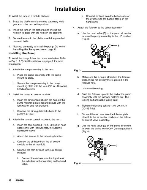
InstallationTo install the ram on a mobile plat<strong>for</strong>m:1. Brace the plat<strong>for</strong>m so it remains stationary whileyou attach the ram to the plat<strong>for</strong>m.2. Place the ram on the plat<strong>for</strong>m and line up theholes in its base with the holes in the plat<strong>for</strong>m.3. Secure the ram to the plat<strong>for</strong>m with the providednuts and bolts.4. Now you are ready to install the pump. Go to theInstalling the Pump section on page 12.Installing the Pumpii.Connect air lines from the bottom side ofthe cylinders to the bottom fitting on thehand valve.4. Attach the follower to the pump assembly:a. Use the hand valve (3) on the pump air controlto raise the pump assembly to the UP position(Fig. 3).3To install the pump, follow the procedure below. Referto Fig. 1, A Typical Installation, on page 8, <strong>for</strong> morein<strong>for</strong>mation.1. Attach the pump assembly to the ram:a. Place the pump assembly onto the pumpmounting plate.b. Secure the pump assembly to the pumpmounting plate with the four 5/16 in.–18 sockethead capscrews.2. Install the pump air control module:a. Insert the air manifold stud in the hole on thepump mounting plate (N) and secure with thelockwasher and nut provided.b. Connect the air regulator kit’s hose to thepump’s air inlet.3. Attach the ram air control module to the ram:a. Insert the four supplied 1/4 in.-20 socket headcapscrews, with lockwashers, through thehand lever valve.Fig. 3b. Make sure the o-ring is already in the followerplate. If it is not already there, place it in thefollower now.c. Lubricate the o-ring.d. Push the follower up onto the end of the pumpassembly until the follower bottoms out. Thelocking bolt should be facing front.e. Tighten the locking bolts to 13.6–20.3 N.m(10–15 ft-lb).f. Connect the air hose from the follower plateblowoff to the air control module on the followerblowoff valve assembly.g. Use the hand valve (3) on the pump air controlto lower the pump to the OFF (neutral) position(Fig. 4).b. Attach the screws to the mounting bracket.c. Connect the air hose from the air controlmodule to the air manifold.3d. Connect the ram air lines to the air controlmodule:i. Connect the airlines from the top side ofthe cylinders to the top fitting on the handvalve.Fig. 412310526


