

308369K 5-, 10-, and 15-Gallon Pressure Tanks ... - Graco Inc.
308369K 5-, 10-, and 15-Gallon Pressure Tanks ... - Graco Inc.
308369K 5-, 10-, and 15-Gallon Pressure Tanks ... - Graco Inc.

Create successful ePaper yourself
Turn your PDF publications into a flip-book with our unique Google optimized e-Paper software.
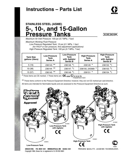
Instructions – Parts ListSTAINLESS STEEL (ASME)5-, <strong>10</strong>-, <strong>and</strong> <strong>15</strong>-<strong>Gallon</strong><strong>Pressure</strong> <strong>Tanks</strong>Maximum Air Inlet <strong>Pressure</strong>: <strong>10</strong>0 psi (0.7 MPa, 7 bar)Maximum Working Fluid <strong>Pressure</strong>Low-<strong>Pressure</strong> Regulated Tank: <strong>15</strong> psi (0.1 MPa, 1 bar)(for HVLP or low–pressure, fine-adjustment applications)High-<strong>Pressure</strong> Regulated Tank: <strong>10</strong>0 psi (0.7 MPa, 7 bar)<strong>308369K</strong>Tank Sizegallons (liters)Low-<strong>Pressure</strong>TankSeries ALow-<strong>Pressure</strong>Tankwith AgitatorSeries BHigh-<strong>Pressure</strong>TankSeries AHigh-<strong>Pressure</strong>Tankwith AgitatorSeries B5 (19) 236143 ** 236146 * 236149 * 236<strong>15</strong>2 *<strong>10</strong> (38) 236144 ** 236147 * 236<strong>15</strong>0, 243589 * 236<strong>15</strong>3 *<strong>15</strong> (57) 236145 ** 236148 * 236<strong>15</strong>1 * 236<strong>15</strong>4 ** These items are CE marked. These items are 0359 II 1/2 G T6ITS03ATEX11251** These items conform to the <strong>Pressure</strong> Equipment Directive; however, they are not CE marked per said directive.All items are intended for flammable liquids <strong>and</strong> are assessed to the <strong>Pressure</strong> Equipment Directive as such.Low-<strong>Pressure</strong> Tankwith AgitatorHigh-<strong>Pressure</strong> Tankwith AgitatorHigh-<strong>Pressure</strong> TankLow-<strong>Pressure</strong> Tank
Table of ContentsWarnings . . . . . . . . . . . . . . . . . . . . . . . . . . . . . . . . . . . . . . 2Typical Systems . . . . . . . . . . . . . . . . . . . . . . . . . . . . . . . . 4Installation . . . . . . . . . . . . . . . . . . . . . . . . . . . . . . . . . . . . . 5Operation . . . . . . . . . . . . . . . . . . . . . . . . . . . . . . . . . . . . . 6Maintenance . . . . . . . . . . . . . . . . . . . . . . . . . . . . . . . . . . . 7PartsLow-<strong>Pressure</strong> <strong>Tanks</strong> . . . . . . . . . . . . . . . . . . . . . . . . . . . 8Low-<strong>Pressure</strong> <strong>Tanks</strong> with Agitator . . . . . . . . . . . . . . <strong>10</strong>High-<strong>Pressure</strong> <strong>Tanks</strong> . . . . . . . . . . . . . . . . . . . . . . . . . 12High-<strong>Pressure</strong> <strong>Tanks</strong> with Agitator . . . . . . . . . . . . . . 14Accessories . . . . . . . . . . . . . . . . . . . . . . . . . . . . . . . . . . 16Dimensions . . . . . . . . . . . . . . . . . . . . . . . . . . . . . . . . . . . 18Technical Data . . . . . . . . . . . . . . . . . . . . . . . . . . . . . . . . 19<strong>Graco</strong> St<strong>and</strong>ard Warranty . . . . . . . . . . . . . . . . . . . . . . 20<strong>Graco</strong> Information . . . . . . . . . . . . . . . . . . . . . . . . . . . . . 20SymbolsWarning SymbolWARNINGThis symbol alerts you to the possibility of seriousinjury or death if you do not follow the instructions.Caution SymbolCAUTIONThis symbol alerts you to the possibility of damage toor destruction of equipment if you do not follow theinstructions.INSTRUCTIONSWARNINGEQUIPMENT MISUSE HAZARDEquipment misuse can cause the equipment to rupture or malfunction <strong>and</strong> result in serious injury. This equipment is for professional use only.Read all instruction manuals, tags, <strong>and</strong> labels before operating the equipment.Use the equipment only for its intended purpose. If you are not sure, call your <strong>Graco</strong> distributor.Do not alter or modify this equipment. Use only genuine <strong>Graco</strong> parts.Check equipment daily. Repair or replace worn or damaged parts immediately.Do not exceed the maximum working pressure of the lowest rated component in your system. Themaximum working fluid pressure of the low-pressure regulated tanks is <strong>15</strong> psi (0.1 MPa, 1 bar).The maximum working fluid pressure of the high-pressure regulated tanks is <strong>10</strong>0 psi (0.7 MPa,7 bar)Use fluids <strong>and</strong> solvents which are compatible with the equipment wetted parts. Refer to theTechnical Data section of all equipment manuals. Read the fluid <strong>and</strong> solvent manufacturer’swarnings.Always wear protective eyewear, gloves, clothing, <strong>and</strong> respirator as recommended by the fluid <strong>and</strong>solvent manufacturer.Comply with all applicable local, state, <strong>and</strong> national fire, electrical, <strong>and</strong> safety regulations.
FIRE AND EXPLOSION HAZARDWARNINGImproper grounding, poor ventilation, open flames, or sparks can cause a hazardous condition <strong>and</strong>result in a fire or explosion <strong>and</strong> serious injury. Ground the equipment <strong>and</strong> the object being sprayed. Refer to Grounding on page 5.If there is any static sparking or you feel an electric shock while using this equipment, stop sprayingimmediately. Do not use the equipment until you identify <strong>and</strong> correct the problem.Do not use 1,1,1–trichloroethane, methylene chloride, other halogenated hydrocarbon solvents, orfluids containing such solvents in aluminum pumps. Such use could result in a serious chemicalreaction, with the possibility of explosion.Do not use kerosene or other flammable solvents or combustible gases to flush the unit.Provide fresh air ventilation to avoid the buildup of flammable fumes from solvents or the fluidbeing sprayed.Keep the spray area free of debris, including solvent, rags, <strong>and</strong> gasoline.Before operating this equipment, electrically disconnect all equipment in the spray area.Before operating this equipment, extinguish all open flames or pilot lights in the spray area.Do not smoke in the spray area.Do not turn on or off any light switch in the spray area while spraying or while there are any fumesin the air.Do not operate a gasoline engine in the spray area.MOVING PARTS HAZARDMoving parts, such as the rotating blades of the agitator, can pinch or amputate your fingers or otherbody parts <strong>and</strong> can cause splashing in the eyes or on the skin.Keep clear of all moving parts when starting or operating the agitator.Always shut off the agitator <strong>and</strong> disconnect the air line before adjusting the angle of the agitator,removing the agitator from the drum, or checking or repairing any part of the agitator.HAZARDOUS VAPORSHazardous fluids or toxic fumes can cause serious injury or death if splashed in the eyes or on theskin, swallowed, or inhaled. When flushing the air motor, keep your face away from the exhaust port.United States Government safety st<strong>and</strong>ards have been adopted under the Occupational Safety <strong>and</strong> Health Act. Youshould consult these st<strong>and</strong>ards –– particularly the General St<strong>and</strong>ards, Part 19<strong>10</strong>, <strong>and</strong> the Construction St<strong>and</strong>ards,Part 1926.
Typical SystemsReference numbers <strong>and</strong> letters in parentheses in the text refer to references in the illustrations <strong>and</strong> the partsdrawings.See page 16 for Accessories that are available from <strong>Graco</strong>. Be sure that all accessories are properly sized towithst<strong>and</strong> the pressures in the system.BA17F3318EGDKEYA Air supply hoseB Main air supplyC Ground clamp & wireD Atomizing air hoseE Fluid hoseF Air spray gunG Air regulator & filter:1/4–18 npt outlets (2)1/2–14 npt inletH Agitator air hose4 Safety Valve17 Air inlet ball valve; 1/4–18 npt(m)18 Fluid outlet ball valve; 3/8–18 npsm(m x f)33 Tank air regulatorE4HCFig. 1
InstallationWARNINGFIRE AND EXPLOSION HAZARDAlways maintain a minimum of 1 in.clearance between rotating agitator parts<strong>and</strong> container to prevent sparks fromcontact.<strong>Pressure</strong> Relief ProcedureWARNINGPRESSURIZED EQUIPMENT HAZARDThe pressure tanks remain pressurized until pressureis manually relieved. To reduce the risk ofserious injury from pressurized fluid or accidentalspray from the gun, always follow this procedure torelieve pressure in the tank at the following times:Before you check or service any part of thespray systemBefore you loosen or remove the pressure tankcover or fill portWhenever you stop spraying1. Shut off the air supply to the tank by closing the airinlet valve (17). Refer to Fig. 2.2. Open the drain cock fitting (7) by turning itcounterclockwise.3. Wait until there is no air escaping through the draincock fitting before removing the cover or openingthe fill port.4. Leave the drain cock fitting (7) open until you havereinstalled the cover or fill port.GroundingCheck your local code for detailed groundinginstructions for your area <strong>and</strong> type of equipment. Besure to ground the pressure tank by connecting oneend of a 12 awg (1.5 mm) minimum ground wire tothe pressure tank <strong>and</strong> the other end of the wire to atrue earth ground.Recommended Hose Sizes (general purpose)FluidAirFor runs of: Use: For runs of: Use:0 to 35 ft (0 to 11 m) 3/8” ID 0 to 50 ft (0 to <strong>15</strong> m) 5/16” ID35 to <strong>10</strong>0 ft (11 to 30 m) 1/2” ID 50 to <strong>10</strong>0 ft (<strong>15</strong> to 30 m) 3/8” ID<strong>10</strong>0 to 200 ft<strong>10</strong>0 ft+ (30 m+) 1/2” ID(30 to 61 m) 3/4” IDInstalling a Heavy Duty AgitatorTo install a heavy duty air operated agitator, seemanual 308371. This agitator is recommended for fluidviscosities over 800 centipoise (cp).Connecting HosesRefer to Fig. 1, page 4. Install an air regulator <strong>and</strong>filter (G) upstream from the air inlet ball valve (17) toremove dirt <strong>and</strong> moisture from the compressed airsupply (B). See Accessories on page 16. Connect anair supply hose (A) between the air inlet ball valve (17)<strong>and</strong> an air outlet of the air regulator <strong>and</strong> filter (G).Connect the atomizing air hose (D) to the air spray gun(F) from an air outlet of air regulator <strong>and</strong> filter (G) orfrom the gun air regulator kit (see Accessories onpage 16).Connect a fluid hose (E) between the 3/8 npt(m)fluid outlet ball valve (18) <strong>and</strong> the fluid inlet of air spraygun (F).177Fig. 2
OperationWARNINGPRESSURIZED EQUIPMENT HAZARDThis is a pressurized tank. Always followthe <strong>Pressure</strong> Relief Procedure on page5 before opening the tank cover or fillport. This reduces the risk of serious injury, includingsplashing in the eyes or on the skin, or injuryfrom moving parts. These injuries can result if thetank pressure is not fully relieved.Preparing the FluidPrepare the fluid according to the manufacturer’sinstructions. Strain the fluid to remove large particlesthat could clog the spray gun or the siphon tube.Filling the Tank1. Before filling the tank, follow the <strong>Pressure</strong> ReliefProcedure on page 5.2. Place fluid into the tank by one of the followingmethods:a. Remove the cover <strong>and</strong> place a 5-gallon pail offluid in the 5-gallon tank (see Dimensions,page 17).b. Remove the cover <strong>and</strong> place a 5-gallonantistatic polyethylene liner in the 5-gallontank. Pour the fluid into the antistaticpolyethylene liner (see Accessories, page16).3. Fill the tank through the fill port in the cover, orremove the cover <strong>and</strong> pour fluid directly into thetank. Do not exceed the suggested capacity (5, <strong>10</strong>or <strong>15</strong> gallons) of your tank.NOTE: If a 5-gallon pail is used inside the tank, anadjustment is required to the agitator paddle positionto avoid interference. See instruction manual 308371for adjustment information.4. Replace the cover or the filler cap (20) <strong>and</strong> tightenthe c–clamp h<strong>and</strong>les securely.Operating the <strong>Pressure</strong> Tank1. Close the tank air regulator (33) by turning theknob counterclockwise <strong>and</strong> turn on the air supply.See Fig. 2.2. Open the air inlet ball valve (17).3. Start <strong>and</strong> adjust the agitator (if it is used) asexplained in the separate instruction manual308371.4. Adjust the tank air regulator (33) to theapproximate pressure desired.5. Open fluid outlet ball valve (18).6. Turn on the atomizing air to the air spray gun. Testspray a small area <strong>and</strong> adjust the pressure asnecessary. Always use the lowest possible airpressure to obtain the desired results.WARNINGPRESSURIZED EQUIPMENT HAZARDOverpressurizing the tank or accessoriescould cause a part to rupture. To reducethe risk of serious injury, includingsplashing in the eyes or on the skin, <strong>and</strong> propertydamage, never exceed the maximum air <strong>and</strong> fluidworking pressure of the lowest rated component inyour system.CAUTIONDo not operate the agitator at a high speed for a longperiod of time. Excessive agitator speed can causefoaming of fluid (making the fluid unusable), vibration,<strong>and</strong> increased wear on the parts. Always agitatethe fluid only enough to maintain even mixing.Safety Relief ValveA safety relief valve (4) will automatically relieve thetank pressure when the air pressure exceeds 95 to<strong>10</strong>0 psi (0.5 to 0.6 MPa, 6.5 to 7 bar). Refer to Fig. 2or the parts drawings.Each week, check the working order of the safety reliefvalve. Only as a test, raise the air pressure to 95 to<strong>10</strong>5 psi (0.5 to 0.6 MPa, 6.5 to 7.1 bar). If the safetyrelief valve does not relieve the pressure, replace itimmediately. Do not attempt to repair it. The safetyrelief valve will reset automatically when the pressureis relieved.
MaintenanceCleaning the Tank1. First follow the <strong>Pressure</strong> Relief Procedure onpage 5.2. Follow the procedure below to force the fluid backthrough the hose <strong>and</strong> into the tank:a. Loosen the spray gun air cap retaining ringabout two turns.b. Hold a rag over the air cap <strong>and</strong> trigger the gunfor a few seconds, until the fluid is forced backinto the tank.3. Remove the tank cover.4. Empty the fluid from the tank <strong>and</strong> pour a suitableamount of solvent into it.CAUTIONBe sure that the solvent you use is compatible withthe fluid being sprayed. Refer to the Technical Datasection on page 19.5. Replace the tank cover <strong>and</strong> tighten the c–clamps.6. Close the drain cock fitting (7).7. Turn on the air supply.8. Hold a metal part of the gun against a groundedmetal waste container <strong>and</strong> trigger the gun into thewaste container until clean solvent comes from thegun.9. Remove the solvent from the system <strong>and</strong> wipe theinside of the tank <strong>and</strong> the rest of the equipmentclean with a solvent-dampened rag.See separate instruction manual 308371 forinformation on agitator maintenance.
PartsLow-<strong>Pressure</strong> Stainless Steel (ASME) <strong>Tanks</strong>Model 236143, 5-gallon sizeModel 236144, <strong>10</strong>-gallon sizeModel 236145, <strong>15</strong>-gallon size341933937258512111932417220<strong>15</strong>181430311629628223512Tank Assembliesinclude tank (27), gasket (28),cover (29), <strong>and</strong> plug (36).Part No. Description236087 TANK ASSY; 5-gallon size236088 TANK ASSY; <strong>10</strong>-gallon size236089 TANK ASSY; <strong>15</strong>-gallon size2736
PartsLow-<strong>Pressure</strong> Stainless Steel (ASME) <strong>Tanks</strong>Model 236143, 5-gallon sizeModel 236144, <strong>10</strong>-gallon sizeModel 236145, <strong>15</strong>-gallon sizeRef.No. Part No. Description Qty.1 1<strong>10</strong>476 ADAPTER, union, straight swivel;3/8 npt(m) to 1/4 npsm(f) 22 <strong>10</strong>0840 ELBOW, street; 1/4-18 npt(m x f) 23 164724 HOSE, coupled; 400 wpr; 1/8-27npt(m) 14 <strong>10</strong>3347 VALVE, safety, <strong>10</strong>0 psi(0.7 Mpa, 7 bar); 1/4-18 npt(m) <strong>15</strong> 189016 MANIFOLD, air inlet; 3/8-18 npt;1/4-18 npt 16 112306 PLUG, pipe; 3/8-18 npt; sst 17 <strong>10</strong>1759 FITTING, drain cock 18 <strong>10</strong>0030 BUSHING;1/8-27 npt(f) x 1/4-18 npt(m) 19 112307 ELBOW, street, 90;1/8-27 npt(f) x 1/8-27 npt(m) 111 1<strong>10</strong>475 TEE, street; zinc plated steel;1/8-27 npt(f) x 1/8-27 npt(m) 1171976 TUBE; 5-gallon size; sst 112 171975 TUBE; <strong>10</strong>-gallon size; sst 1171974 TUBE; <strong>15</strong>-gallon size; sst 114 <strong>15</strong>6849 NIPPLE, pipe; 3/8-18 npt 1<strong>15</strong> 171988 GASKET; chlororene rubber<strong>and</strong> cork 116 1<strong>10</strong>756 ELBOW, street, 90;3/8 npt x 3/8 npt; sst 117 208390 VALVE, ball; 1/4-18 npt(m)See 307068 for parts 118 237533 VALVE, ball; sst;3/8-18 npsm(m x f),See 307068 for parts 119 <strong>10</strong>0139 PLUG, pipe, headless;1/8-27 npt 220 2<strong>10</strong>575 CAP, filler 121 176373 LABEL, Warning (not shown) 1Ref.No. Part No. Description Qty.22 188784 NUT, jam; 1-1/2-12-unf-2b; sst 125 <strong>15</strong><strong>15</strong>19 NIPPLE, reducing; 1/4-1/8 npt 1236087 TANK; 5-gallon size; sst<strong>Inc</strong>ludes items 28, 29 & 36 127 236088 TANK; <strong>10</strong>-gallon size; sst<strong>Inc</strong>ludes items 28, 29 & 36 1236089 TANK; <strong>15</strong>-gallon size; sst<strong>Inc</strong>ludes items 28, 29 & 36 128 117571 GASKET; Santoprene 129 COVER, tank; sst 130 188880 PLUG, lid; sst 131 <strong>10</strong>3414 O-RING, packing; Viton 132 <strong>10</strong>4813 PLUG, pipe; 3/8-18 npt 133 11<strong>15</strong>01 REGULATOR; 0 to <strong>15</strong> psi(0 to 0.1 MPa, 0 to 1 bar) 134 1<strong>10</strong>444 GAUGE, pressure, air; 0 to <strong>15</strong> psi(0 to 0.1 MPa, 0 to 1 bar) 135 1<strong>10</strong>143 T-HANDLE 636 PLUG, bottom; 3/4-14 npt 138LINER, antistatic polyethylene;(not shown) 1 Keep these spare parts on h<strong>and</strong> to reduce downtime.A C–clamp replacement Kit is available. It includesthe T-h<strong>and</strong>le, C–clamp, pin, <strong>and</strong> cotter pin.Order 111381.To purchase a box of antistatic polyethylene liners,see Accessories on page 16.NOTE: The 307 numbers in the descriptions refer toseparate instruction manuals.
PartsLow-<strong>Pressure</strong> Stainless Steel (ASME) <strong>Tanks</strong> W/AgitatorModel 236146, 5-gallon sizeModel 236147, <strong>10</strong>-gallon sizeModel 236148, <strong>15</strong>-gallon size 1722342373391912920<strong>15</strong>18339711148532421628612Agitator bearing notincluded with5-gallon tank assy.See Manual 308371for agitator parts.Tank Assemblies35include tank (27), gasket (28),cover (29), <strong>and</strong> plug (36).Part No. Description236087 TANK ASSY; 5-gallon size236088 TANK ASSY; <strong>10</strong>-gallon size236089 TANK ASSY; <strong>15</strong>-gallon sizeAgitator AssembliesPart No. Description236661 AGITATOR ASSY; 5-gallon size236662 AGITATOR ASSY; <strong>10</strong>-gallon size236663 AGITATOR ASSY; <strong>15</strong>-gallon size2736
PartsLow-<strong>Pressure</strong> Stainless Steel (ASME) <strong>Tanks</strong> W/AgitatorModel 236146, 5-gallon sizeModel 236147, <strong>10</strong>-gallon sizeModel 236148, <strong>15</strong>-gallon sizeRef.No. Part No. Description Qty.1 1<strong>10</strong>476 ADAPTER, union, straight swivel;3/8 npt(m) to 1/4 npsm(f) 22 <strong>10</strong>0840 ELBOW, street; 1/4-18 npt(m x f) 23 164724 HOSE, coupled; 400 wpr; 1/8-27npt(m) 14 <strong>10</strong>3347 VALVE, safety, <strong>10</strong>0 psi(0.7 MPa, 7 bar); 1/4-18 npt(m) <strong>15</strong> 189016 MANIFOLD, air inlet; 3/8-18 npt;1/4-18 npt 16 112306 PLUG, pipe; 3/8-18 npt; sst 17 <strong>10</strong>1759 FITTING, drain cock 18 <strong>10</strong>0030 BUSHING;1/8-27 npt(f) x 1/4-18 npt(m) 19 112307 ELBOW, street, 90;1/8-27 npt(f) x 1/8-27 npt(m) 111 1<strong>10</strong>475 TEE, street; zinc plated steel;1/8-27 npt(f) x 1/8-27 npt(m) 1171976 TUBE; 5 gallon size; sst 112 171975 TUBE; <strong>10</strong> gallon size; sst 1171974 TUBE; <strong>15</strong> gallon size; sst 114 <strong>15</strong>6849 NIPPLE, pipe; 3/8-18 npt 1<strong>15</strong> 171988 GASKET; chlororene rubber<strong>and</strong> cork 116 1<strong>10</strong>756 ELBOW, street, 90;3/8 npt x 3/8 npt; sst 117 208390 VALVE, ball; 1/4-18 npt(m)See 307068 for parts 118 237533 VALVE, ball; sst;3/8-18 npsm(m x f),See 307068 for parts 119 <strong>15</strong><strong>15</strong>19 NIPPLE, reducing; 1/4-1/8 npt 120 2<strong>10</strong>575 CAP, filler 121 176373 LABEL, Warning (not shown) 1Ref.No. Part No. Description Qty.236661 AGITATOR, pressure, tank;5 gallon size; sst 122 236662 AGITATOR, pressure, tank;<strong>10</strong> gallon size; sst 1236663 AGITATOR, pressure, tank;<strong>15</strong> gallon size; sst 1236087 TANK; 5 gallon size; sst<strong>Inc</strong>ludes items 28, 29 & 36 127 236088 TANK; <strong>10</strong> gallon size; sst<strong>Inc</strong>ludes items 28, 29 & 36 1236089 TANK; <strong>15</strong> gallon size; sst<strong>Inc</strong>ludes items 28, 29 & 36 128 117571 GASKET; Santoprene 129 COVER, tank; sst 132 <strong>10</strong>4813 PLUG, pipe; 3/8-18 npt 133 11<strong>15</strong>01 REGULATOR; 0 to <strong>15</strong> psi(0 to 0.1 MPa, 0 to 1 bar) 134 1<strong>10</strong>444 GAUGE, pressure, air; 0-<strong>15</strong> psi(0 to 0.1 MPa, 0 to 1 bar) 135 1<strong>10</strong>143 T-HANDLE 636 PLUG, bottom; 3/4-14 npt 137 <strong>10</strong>0139 PLUG, pipe; 1/8 npt 138LINER, antistatic polyethylene;(not shown) 139 222011 CLAMP, grounding 1 Keep these spare parts on h<strong>and</strong> to reduce downtime.A C–clamp replacement Kit is available. It includesthe T–h<strong>and</strong>le, C–clamp, pin, <strong>and</strong> cotter pin.Order 111381.To purchase a box of antistatic polyethylene liners,see Accessories on page 16.NOTE: The 307 numbers in the descriptions refer toseparate instruction manuals.
PartsHigh-<strong>Pressure</strong> Stainless Steel (ASME) <strong>Tanks</strong>Model 236149, 5-gallon size, includes items 1–38Model 236<strong>15</strong>0, <strong>10</strong>-gallon size, includes items 1–38Model 243589, <strong>10</strong>-gallon size, includes items 2–16, 19–22, 27–32, 36–38Model 236<strong>15</strong>1, <strong>15</strong>-gallon size, includes items 1–381343525217331993242032<strong>15</strong>7118530311816142962822123627Tank Assembliesinclude tank (27), gasket (28),cover (29), <strong>and</strong> plug (37).Part No. Description236087 TANK ASSY; 5-gallon size236088 TANK ASSY; <strong>10</strong>-gallon size236089 TANK ASSY; <strong>15</strong>-gallon size37
PartsHigh-<strong>Pressure</strong> Stainless Steel (ASME) <strong>Tanks</strong>Model 236149, 5-gallon size, includes items 1–38Model 236<strong>15</strong>0, <strong>10</strong>-gallon size, includes items 1–38Model 243589, <strong>10</strong>-gallon size, includes items 2–16, 19–22, 27–32, 36–38Model 236<strong>15</strong>1, <strong>15</strong>-gallon size, includes items 1–38Ref.No. Part No. Description Qty.1* <strong>10</strong>0361 PLUG, pipe, headless;1/2-14 npt(f) 12 <strong>10</strong>0840 ELBOW, street; 1/4-18 npt(m x f) 23 164724 HOSE, coupled; 400 wpr; 1/8-27npt(m) 14 <strong>10</strong>3347 VALVE, safety, <strong>10</strong>0 psi(0.7 MPa, 7 bar); 1/4-18 npt(m) <strong>15</strong> 189016 MANIFOLD, air inlet; 3/8-18 npt;1/4-18 npt 16 112306 PLUG, pipe; 3/8-18 npt; sst 17 <strong>10</strong>1759 FITTING, drain cock 18 <strong>10</strong>0030 BUSHING;1/8-27 npt(f) x 1/4-18 npt(m) 19 112538 ELBOW, street, 90;1/8-27 npt(f) x 1/4-18 npt(m) 111 1<strong>10</strong>475 TEE, street; zinc plated steel;1/8-27 npt(f) x 1/8-27 npt(m) 1171976 TUBE; 5-gallon size; sst 112 171975 TUBE; <strong>10</strong>-gallon size; sst 1171974 TUBE; <strong>15</strong>-gallon size; sst 114 <strong>15</strong>6849 NIPPLE, pipe; 3/8-18 npt 1<strong>15</strong> 171988 GASKET; chlororene rubber<strong>and</strong> cork 116 1<strong>10</strong>756 ELBOW, street, 90;3/8 npt x 3/8 npt; sst 117* 208390 VALVE, ball; 1/4-18 npt(m)See 307068 for parts 118* 237533 VALVE, ball; sst;3/8-18 npsm(m x f),See 307068 for parts 119 <strong>10</strong>0139 PLUG, pipe, headless;1/8-27 nptf 120 2<strong>10</strong>575 CAP, filler 121 176373 LABEL, Warning (not shown) 122 188784 NUT, jam; 1-1/2-12-unf-2b; sst 125* <strong>15</strong>5665 UNION, adapter;3/8 npt x 3/8 npsm 1Ref.No. Part No. Description Qty.236087 TANK; 5-gallon size; sst<strong>Inc</strong>ludes items 28, 29 & 37 127 236088 TANK; <strong>10</strong>-gallon size; sst<strong>Inc</strong>ludes items 28, 29 & 37 1236089 TANK; <strong>15</strong>-gallon size; sst<strong>Inc</strong>ludes items 28, 29 & 37 128 117571 GASKET; Santoprene 129 COVER, tank; sst 130 188880 PLUG, lid; sst 131 <strong>10</strong>3414 O-RING, packing; Viton 132 <strong>10</strong>4813 PLUG, pipe; 3/8-18 npt 133* 171937 REGULATOR, air; 2 to 125 psi(0.01 to 0.8 MPa, 0.1 to 9 bar) 134* 160430 GAUGE, pressure, air; 0 to<strong>10</strong>0 psi(0 to 0.7 MPa, 0 to 7 bar) 135* <strong>15</strong>9239 NIPPLE, pipe, reducing;1/2-14 npt x 3/8-18 npt 136 1<strong>10</strong>143 T-HANDLE 637 PLUG, bottom; 3/4-14 npt 138LINER, antistatic polyethylene;(not shown) 1 Keep these spare parts on h<strong>and</strong> to reduce downtime.A C–clamp replacement Kit is available. It includesthe T–h<strong>and</strong>le, C–clamp, pin, <strong>and</strong> cotter pin.Order 111381.To purchase a box of antistatic polyethylene liners,see Accessories on page 16.* Not included with Model 243589.NOTE: The 307 numbers in the descriptions refer toseparate instruction manuals.
PartsHigh-<strong>Pressure</strong> Stainless Steel (ASME) <strong>Tanks</strong> W/AgitatorModel 236<strong>15</strong>2, 5-gallon sizeModel 236<strong>15</strong>3, <strong>10</strong>-gallon sizeModel 236<strong>15</strong>4, <strong>15</strong>-gallon size2234135 25 2 173320185<strong>15</strong>91631471183242923962812Agitator bearing notincluded with5-gallon tank assy.See Manual 308371for agitator parts.Tank Assemblies36include tank (27), gasket (28),cover (29) <strong>and</strong> plug (37).Part No. Description236087 TANK ASSY; 5-gallon size236088 TANK ASSY; <strong>10</strong>-gallon size236089 TANK ASSY; <strong>15</strong>-gallon sizeAgitator AssembliesPart No. Description236661 AGITATOR ASSY; 5-gallon size236662 AGITATOR ASSY; <strong>10</strong>-gallon size236663 AGITATOR ASSY; <strong>15</strong>-gallon size2737
PartsHigh-<strong>Pressure</strong> Stainless Steel (ASME) <strong>Tanks</strong> W/AgitatorModel 236<strong>15</strong>2, 5-gallon sizeModel 236<strong>15</strong>3, <strong>10</strong>-gallon sizeModel 236<strong>15</strong>4, <strong>15</strong>-gallon sizeRef.No. Part No. Description Qty.1 <strong>10</strong>0361 PLUG, pipe, hdless;1/2-14 npt(f) 12 <strong>10</strong>0840 ELBOW, street; 1/4-18 npt(m x f) 23 164724 HOSE, coupled; 400 wpr; 1/8-27npt(m) 14 <strong>10</strong>3347 VALVE, safety, <strong>10</strong>0 psi(0.7 Mpa, 7 bar);1/4-18 npt(m) <strong>15</strong> 189016 MANIFOLD, air inlet; 3/8-18 npt;1/4-18 npt 16 112306 PLUG, pipe; 3/8-18 npt; sst 17 <strong>10</strong>1759 FITTING, drain cock 18 <strong>10</strong>0030 BUSHING;1/8-27 npt(f) x 1/4-18 npt(m) 19 112538 ELBOW, street, 90;1/8-27 npt(f) x 1/4-18 npt(m) 111 1<strong>10</strong>475 TEE, street; zinc plated steel;1/8-27 npt(f) x 1/8-27 npt(m) 1171976 TUBE; 5-gallon size; sst 112 171975 TUBE; <strong>10</strong>-gallon size; sst 1171974 TUBE; <strong>15</strong>-gallon size; sst 114 <strong>15</strong>6849 NIPPLE, pipe; 3/8-18 npt 1<strong>15</strong> 171988 GASKET; chlororene rubber<strong>and</strong> cork 116 1<strong>10</strong>756 ELBOW, street, 90;3/8 npt x 3/8 npt; sst 117 208390 VALVE, ball; 1/4-18 npt(m)See 307068 for parts 118 237533 VALVE, ball; sst;3/8-18 npsm(m x f),See 307068 for parts 119 176373 LABEL, Warning (not shown) 120 2<strong>10</strong>575 CAP, filler 121 <strong>15</strong>5665 UNION, adapter;3/8 npt x 3/8 npsm 1236661 AGITATOR, pressure, tank;5-gallon size; sst 122 236662 AGITATOR, pressure, tank;<strong>10</strong>-gallon size; sst 1236663 AGITATOR, pressure, tank;<strong>15</strong>-gallon size; sst 1Ref.No. Part No. Description Qty.236087 TANK; 5-gallon size; sst<strong>Inc</strong>ludes items 28, 29 & 37 127 236088 TANK; <strong>10</strong>-gallon size; sst<strong>Inc</strong>ludes items 28, 29 & 37 1236089 TANK; <strong>15</strong>-gallon size; sst<strong>Inc</strong>ludes items 28, 29 & 37 128 117571 GASKET; Santoprene 129 COVER, tank; sst 132 <strong>10</strong>4813 PLUG, pipe; 3/8-18 npt 133 171937 REGULATOR. air; 2 to 125 psi(0.01 to 0.8 MPa, 0.1 to 9 bar) 134 160430 GAUGE, pressure, air; 0 to<strong>10</strong>0 psi(0 to 0.7 MPa, 0 to 7 bar) 135 <strong>15</strong>9239 NIPPLE, pipe, reducing;1/2-14 npt x 3/8-18 npt 136 1<strong>10</strong>143 T-HANDLE 637 PLUG, bottom 138LINER, antistatic polyethylene;(not shown) 139 222011 CLAMP, grounding 1 Keep these spare parts on h<strong>and</strong> to reduce downtime.A C–clamp replacement Kit is available. It includesthe T–h<strong>and</strong>le, C–clamp, pin, <strong>and</strong> cotter pin.Order 111381.To purchase a box of antistatic polyethylene liners,see Accessories on page 16.NOTE: The 307 numbers in the descriptions refer toseparate instruction manuals.
AccessoriesStrainer 202271300 psi (2.1 MPa, 21 bar) Maximum Working <strong>Pressure</strong>Install at the tank air inlet to remove dirt <strong>and</strong> moisturefrom the air supply, or at the tank fluid outlet to removeparticles from the paint which could clog the spray gunnozzle.Gun Air Regulator Kit 235042<strong>10</strong>0 psi (0.7 MPa, 7 bar) Working <strong>Pressure</strong>To supply atomizing air to a spray gun from thepressure pot.Buna–N Air Supply Hose200 psi (1.4 MPa, 14 bar) Maximum Working <strong>Pressure</strong>5/16“ ID; cpld 1/4 npsm(f) swivel2<strong>10</strong>866 <strong>15</strong> ft (4.6 m) long2<strong>10</strong>867 25 ft (7.6 m) longLow-<strong>Pressure</strong> Regulator Conversion Kit 235041<strong>15</strong> psi (0.1 MPa, 1 bar) Working <strong>Pressure</strong>. 0 to <strong>15</strong> psi(0 to 0.1 MPa, 0 to 1 bar) regulated pressure rangeNylon Fluid Supply Hose300 psi (2.1 MPa, 21 bar) Maximum Working <strong>Pressure</strong>3/8” ID; cpld 3/8 npsm(fbe) swivel; neoprene cover205160 <strong>15</strong> ft (4.6 m) long205142 25 ft (7.6 m) long205143 50 ft (<strong>15</strong>.2 m) longBottom Outlet Kit 236677For bottom outlet fluid feeding.To convert to a low-pressure regulator assembly.St<strong>and</strong>ard Agitator Air Gearmotor Repair Kit 236675For repair of worn air gear motors.High-<strong>Pressure</strong> Regulator Conversion Kit 236680<strong>10</strong>0 psi (0.7 MPa, 7 bar) Working <strong>Pressure</strong>. 0 to <strong>10</strong>0psi (0 to 0.7 MPa, 0 to 7 bar) regulated pressure rangeTo convert to a high-pressure regulator assembly.Air Regulator <strong>and</strong> Filter 202660<strong>10</strong>0 psi (0.7 MPa, 7 bar) Maximum Working <strong>Pressure</strong>For air regulation <strong>and</strong> filtration.Heavy Duty AgitatorTo convert from a st<strong>and</strong>ard agitator assembly to aheavy duty agitator assembly. Recommended for fluidviscosities over 800 cp.236661 5-gallon tank size236662 <strong>10</strong>-gallon tank size236663 <strong>15</strong>-gallon tank sizeC–clamp Replacement Kit 111381To replace the pressure tank C–clamp assembly. Thekit includes the T–h<strong>and</strong>le, C–clamp, pin, <strong>and</strong> cotter pin.Antistatic Polyethylene Tank LinersLiners fit inside the tank. For ease of cleanup <strong>and</strong>maintenance.<strong>15</strong>D059 5-gallon tank size (Quantity of 20)<strong>15</strong>D060 <strong>10</strong>-gallon tank size (Quantity of 20)<strong>15</strong>D061 <strong>15</strong>-gallon tank size (Quantity of 8)Stainless Steel Agitator Paddle 186517Material of 304 stainless steel welded construction.Replaces plastic agitator paddle 236098.PTFE Coated Gasket 117574Optional replacement for st<strong>and</strong>ard 117571 gasket.
Notes
Dimensionsoverall height(see chart)19” (483 mm)tank shownwithout coverDim. Y(see chart)5-gallon pail12.6” (320.5 mm)14” (356 mm)PaintOverallBucketSize Model Height Net Weight Dim. Y5 <strong>Gallon</strong> 236143 30.5“ (775 mm) 65 lb (30 kg)236149 30.5“ (775 mm) 65 lb (30 kg) 13.19”236146 30.5“ (775 mm) 86 lb (39 kg) (335 mm)236<strong>15</strong>2 30.5“ (775 mm) 74 lb (34 kg)<strong>10</strong> <strong>Gallon</strong> 236144 33.87“ (860 mm) 76 lb (35 kg)236<strong>15</strong>0 33.87“ (860 mm) 76 lb (35 kg) 18.19”236147 33.87“ (860 mm) 97 lb (44 kg) (462 mm)236<strong>15</strong>3 33.87“ (860 mm) 85 lb (39 kg)<strong>15</strong> <strong>Gallon</strong> 236145 44.57“ (1132 mm) 92 lb (42 kg)236<strong>15</strong>1 44.57“ (1132 mm) 92 lb (42 kg) 28.94”236148 44.57“ (1132 mm) 113 lb (51 kg) (735 mm)236<strong>15</strong>4 44.57“ (1132 mm) <strong>10</strong>1 lb (46 kg)
Technical DataActual tank capacities5-gallon size: 8.8 U.S. gal (33 liter)<strong>10</strong>-gallon size: 12.6 U.S. gal (48 liter)<strong>15</strong>-gal size: 19.3 U.S. gal (72 liter)Maximum working pressureLow pressure regulated tank: <strong>15</strong> psi(0.1 MPa, 1 bar)High pressure regulated tank: <strong>10</strong>0 psi(0.7 Mpa, 7 bar)Relief valve setting: <strong>10</strong>0 psi (0.7 MPa, 7 bar)St<strong>and</strong>ard agitator air consumption(continuous duty):<strong>15</strong> cfm (0.42 m/min) at 60 rpm <strong>and</strong> 80 psi(0.5 MPa, 5 bar) air supply pressureAir inlet size: 1/4–18 npt(m)Fluid outlet size: 3/8–18 npsm(m)Bottom outlet size: 3/4–14 npt(f)Wetted partsModels without agitator: 304 & 316 stainless steel,Santoprene, Zytel, <strong>and</strong> MylarModels with agitator: 304 & 316 stainless steel,Santoprene, Zytel, Mylar, Teflon, <strong>and</strong> bronze* Sound power level at<strong>10</strong>0 psi (0.7 MPa, 7 bar): 92 dBa* Sound pressure level at<strong>10</strong>0 psi (0.7 MPa, 7 bar): 82 dBa* Sound power level <strong>and</strong> sound pressure levelmeasured per ISO 9614–2.Zytel, Mylar, <strong>and</strong> Teflon are registered trademarksof the DuPont Company.Santoprene is a registered trademark of theAdvanced Elastomer Systems, L.P.Weight: See chart on page 18.
<strong>Graco</strong> St<strong>and</strong>ard Warranty<strong>Graco</strong> warrants all equipment manufactured by <strong>Graco</strong> <strong>and</strong> bearing its name to be free from defects in material <strong>and</strong> workmanship on thedate of sale to the original purchaser for use. With the exception of any special, extended, or limited warranty published by <strong>Graco</strong>,<strong>Graco</strong> will, for a period of twelve months from the date of sale, repair or replace any part of the equipment determined by <strong>Graco</strong> to bedefective. This warranty applies only when the equipment is installed, operated <strong>and</strong> maintained in accordance with <strong>Graco</strong>’s writtenrecommendations.This warranty does not cover, <strong>and</strong> <strong>Graco</strong> shall not be liable for general wear <strong>and</strong> tear, or any malfunction, damage or wear caused byfaulty installation, misapplication, abrasion, corrosion, inadequate or improper maintenance, negligence, accident, tampering, orsubstitution of non-<strong>Graco</strong> component parts. Nor shall <strong>Graco</strong> be liable for malfunction, damage or wear caused by the incompatibility of<strong>Graco</strong> equipment with structures, accessories, equipment or materials not supplied by <strong>Graco</strong>, or the improper design, manufacture,installation, operation or maintenance of structures, accessories, equipment or materials not supplied by <strong>Graco</strong>.This warranty is conditioned upon the prepaid return of the equipment claimed to be defective to an authorized <strong>Graco</strong> distributor forverification of the claimed defect. If the claimed defect is verified, <strong>Graco</strong> will repair or replace free of charge any defective parts. Theequipment will be returned to the original purchaser transportation prepaid. If inspection of the equipment does not disclose any defectin material or workmanship, repairs will be made at a reasonable charge, which charges may include the costs of parts, labor, <strong>and</strong>transportation.THIS WARRANTY IS EXCLUSIVE, AND IS IN LIEU OF ANY OTHER WARRANTIES, EXPRESS OR IMPLIED, INCLUDING BUTNOT LIMITED TO WARRANTY OF MERCHANTABILITY OR WARRANTY OF FITNESS FOR A PARTICULAR PURPOSE.<strong>Graco</strong>’s sole obligation <strong>and</strong> buyer’s sole remedy for any breach of warranty shall be as set forth above. The buyer agrees that no otherremedy (including, but not limited to, incidental or consequential damages for lost profits, lost sales, injury to person or property, or anyother incidental or consequential loss) shall be available. Any action for breach of warranty must be brought within two (2) years of thedate of sale.<strong>Graco</strong> makes no warranty, <strong>and</strong> disclaims all implied warranties of merchantability <strong>and</strong> fitness for a particular purpose in connectionwith accessories, equipment, materials or components sold but not manufactured by <strong>Graco</strong>. These items sold, but not manufacturedby <strong>Graco</strong> (such as electric motors, switches, hose, etc.), are subject to the warranty, if any, of their manufacturer. <strong>Graco</strong> will providepurchaser with reasonable assistance in making any claim for breach of these warranties.In no event will <strong>Graco</strong> be liable for indirect, incidental, special or consequential damages resulting from <strong>Graco</strong> supplying equipmenthereunder, or the furnishing, performance, or use of any products or other goods sold hereto, whether due to a breach of contract,breach of warranty, the negligence of <strong>Graco</strong>, or otherwise.FOR GRACO CANADA CUSTOMERSThe parties acknowledge that they have required that the present document, as well as all documents, notices <strong>and</strong> legal proceedingsentered into, given or instituted pursuant hereto or relating directly or indirectly hereto, be drawn up in English. Les partiesreconnaissent avoir convenu que la rédaction du présente document sera en Anglais, ainsi que tous documents, avis et procéduresjudiciaires exécutés, donnés ou intentés à la suite de ou en rapport, directement ou indirectement, avec les procedures concernées.<strong>Graco</strong> InformationTO PLACE AN ORDER, contact your <strong>Graco</strong> distributor, or call one of the following numbersto identify the distributor closest to you:1–800–367–4023 Toll Free612–623–6921612–378–3505 FaxAll written <strong>and</strong> visual data contained in this document reflects the latest product information available at the time of publication.<strong>Graco</strong> reserves the right to make changes at any time without notice.Sales Offices: Minneapolis, DetroitInternational Offices: Belgium, Korea, Hong Kong, JapanGRACO INC. P.O. BOX 1441 MINNEAPOLIS, MN 55440–1441www.graco.comPRINTED IN USA 308369 03/1994, Revised 09/2003


