309244D 50:1 Ratio Double Acting Falcon Grease Pumps - Graco Inc.
309244D 50:1 Ratio Double Acting Falcon Grease Pumps - Graco Inc.
309244D 50:1 Ratio Double Acting Falcon Grease Pumps - Graco Inc.
Create successful ePaper yourself
Turn your PDF publications into a flip-book with our unique Google optimized e-Paper software.
INJECTION HAZARDWARNINGFluid dispensed from the valve, leaks or ruptured components can inject fluid into your body andcause extremely serious injury, including the need for amputation. Fluid splashed in the eyes or on theskin can also cause serious injury.Fluid injected into the skin might look like just a cut, but it is a serious injury. Get immediate medicalattention.Do not point the valve at anyone or at any part of the body.Do not put your hand or fingers over the spray nozzle.Do not stop or deflect leaks with your hand, body, glove or rag.Do not “blow back” fluid; this is not an air spray system.Always have the tip guard and the trigger guard on the gun/valve when dispensing.Be sure the valve trigger safety operates before dispensing.Lock the valve trigger safety when you stop dispensing.Follow the Pressure Relief Procedure on page 10 if the nozzle clogs and before cleaning, checkingor servicing the equipment.Tighten all fluid connections before operating the equipment.Check the hoses, tubes, and couplings daily. Replace worn, damaged, or loose parts immediately.Permanently coupled hoses cannot be repaired; replace the entire hose.MOVING PARTS HAZARDMoving parts can pinch or amputate your fingers.Keep clear of all moving parts when starting or operating the pump.Before checking or servicing the equipment, follow the Pressure Relief Procedure on page 10 toprevent the equipment from starting unexpectedly.
FIRE AND EXPLOSION HAZARDWARNINGImproper grounding, poor ventilation, open flames or sparks can cause a hazardous condition and resultin a fire or explosion and serious injury. Ground the equipment and the object being dispensed to. Refer to Grounding on page 6.If there is any static sparking or you feel an electric shock while using this equipment, stop dispensingimmediately. Do not use the equipment until you identify and correct the problem.Provide fresh air ventilation to avoid the buildup of flammable fumes from solvents or the fluidbeing dispensed.Keep the dispense area free of debris, including solvent, rags, and gasoline.Do not smoke in the dispense area.Do not turn on or off any light switch in the dispense area while dispensing or while operating iffumes are present.TOXIC FLUID HAZARDHazardous fluid or toxic fumes can cause serious injury or death if splashed in the eyes or on the skin,inhaled, or swallowed.Know the specific hazards of the fluid you are using.Store hazardous fluid in an approved container. Dispose of hazardous fluid according to all local,state and national guidelines.The air motor exhausts any fluids added to the input air, such as oil or antifreeze.Always wear protective eyewear, gloves, clothing and respirator as recommended by the fluid andsolvent manufacturer.
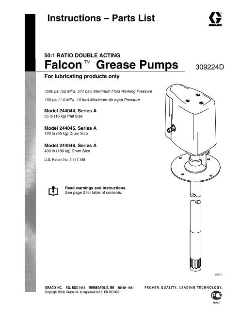
IntroductionWARNINGThese pumps area designed to be used only inpumping non-corrosive and non-abrasive lubricantsand greases. Any other use of the pump can causeunsafe operating conditions and component rupture,which can result in fluid injection or otherserious injury, or fire or explosion.CAUTIONNever run the pump without the muffler installed.NOTE: Be sure that all operators read and understandthis entire manual and any separate manuals suppliedwith components and accessories before using thisequipment.NOTE: Reference numbers and letters used in the textrefer to the callouts in the figures and the parts drawing.N1TermsWARNING: Alerts the user to avoid or correct conditionsthat could cause serious injury.CAUTION: Alerts the user to avoid or correct conditionsthat could cause damage to or destroy equipment.36NOTE: Identifies helpful procedures and information.DISPENSE VALVE: Any fluid dispensing device thatcan be triggered on and off.Component DescriptionThis equipment consists of two major components: theair motor (1) and the displacement pump. See Fig. 1 .The pump is an in-line design, which means that thedisplacement pump screws directly into the motor,without the use of tie rods or couplers. The displacementpump can be placed directly in the fluid beingpumped.The pump is available in three different lengths, basedon the size of the fluid container. Refer to the front coverfor available sizes. The pumps differ only in length;operation and packings are the same. All three pumpsuse the same Air Motor.Make sure the muffler (36) is securely installed in theexhaust port (N) before you operate the pump. SeeFig. 1.Fig. 18757C
InstallationNOTE: Always use Genuine <strong>Graco</strong> Parts and Accessories,available from your <strong>Graco</strong> distributor.GroundingWARNINGFIRE AND EXPLOSION HAZARDBefore operating the pump, ground thesystem as explained below. Also readthe section FIRE OR EXPLOSIONHAZARD on page 4.Air hoses: Use only grounded air hoses.Dispensing Valve: Obtain grounding throughconnection to a properly grounded fluid hose andpump.Fluid supply container: Follow your local code.Air compressor: Follow your local code.To maintain grounding continuity when flushing orrelieving pressure, hold a metal part of the spraygun firmly to the side of a grounded metal pail, thentrigger the gun.Ground all of this equipment:Pump: Remove ground screw (Z) and insertthrough the eye of the ring terminal at the end ofground wire (Y). Fasten ground screw back ontothe pump and tighten securely. Connect the otherend of the wire to a true earth ground. See Fig. 2.Order part number 222011 Grounding Clamp andWire.ZYFluid hoses: Use only grounded fluid hoses.Fig. 2TI1052
InstallationThe Typical Installation shown in Fig. 3 is only a guide for selecting and installing system components andaccessories. Contact your <strong>Graco</strong> distributor for assistance in designing a system to suit your particular needs.If you supply your own accessories, be sure they are adequately sized and pressure-rated to meet the system’srequirements. See the Maximum Working Pressure warning on page 8.KEYA PumpB Bleed-type master air valve (required, Part No. 110224)C Air regulatorD Air hoseE Air line quick disconnectF Air line filterG Bleed-type master air valve (for accessories, Part No. 110224))H Main air lineJ Gun holderK Follow plateL Fluid hoseM Dispense valveY Ground wire (required, Part No. 222011)EAMFGHLDBCYJKThe pump intakeshould be no morethan 1/2 in. (13 mm)off the bottom of thefluid container.Fig. 38758B
InstallationMounting the Pump1. Select a convenient location for the equipment, toensure easy operator access to the pump aircontrols, sufficient room to change supply containers,and a secure mounting platform.2. If using a follow plate (K), remove the fluid containercover. To prevent air from being trapped underthe follow plate, scoop grease from the center ofthe container to the sides, to make the surfaceconcave. Place the follow plate on the grease andpush down on the plate until grease appears at thecenter opening (P). See Fig 4.4. Position the pump (A) so its intake valve is nomore than 1/2 in. (13 mm) from the bottom of thecontainer. Mount the pump to the cover or othersuitable mounting device.WARNINGMount the pump securely so that it cannot movearound during operation. Failure to do so couldresult in personal injury or equipment damage.System AccessoriesWARNINGMaximum Working Pressure23Concave SurfacePush Downon Plate2P3 3KThe maximum working pressure of each componentin your system may not be the same. Toreduce the risk of overpressurizing any part of yoursystem, be sure you know the maximum workingpressure rating of each component. Never exceedthe maximum working pressure of the lowest ratedcomponent connected to a pump. Use the followingtable to limit the air to the pump so that no air lineor fluid line component or accessory is overpressurized.ApproximateAir Inlet Pressure Fluid Outlet Pressurepsi (MPa, bar) psi (MPa, bar)Fig. 4020<strong>50</strong>40 (0.28, 2.8) 2000 (14, 140)60 (0.42, 4.2) 3000 (21, 210)80 (0.56, 5.6) 4000 (28, 280)100 (0.7, 7.0) <strong>50</strong>00 (35, 3<strong>50</strong>)120 (0.84, 8.4) 6000 (42, 420)140 (0.98, 9.8) 7000 (49, 490)1<strong>50</strong> (0.9, 10) 7<strong>50</strong>0 (52, 517)3. Guide the pump intake valve through the coverand follow plate. Secure the cover to the container.
InstallationWARNINGA bleed-type master air valve is required in yoursystem to help reduce the risk of serious injury,including splashing in the eyes or on the skin, andinjury from moving parts if you are adjusting orrepairing the pump.The bleed-type master air valve relieves air trappedbetween this valve and the pump after the air isshut off. Trapped air can cause the pump to cycleunexpectedly. Locate the valve close to the pump.1. Install a bleed-type master air valve (B), to relieveair trapped between the valve and the motor. Seethe WARNING above).2. Install an air regulator (C), to control the pumpspeed and pressure.3. Install an air line filter (F) to remove harmful dirtand moisture from the compressed air supply.4. Install a second bleed-type master air valve (G)upstream from all other accessories, to isolate theaccessories for servicing.5. Connect the fluid hose (L) to the dispensevalve (M). Use a gun holder (J) to hold the dispensevalve when not in use.6. For ease in connecting the air line to the pump,use an air line quick disconnect (E) at the pump airinlet.7. Connect the air (D) and fluid hoses (L) to the pump(A). Use only grounded fluid and air hoses. Besure all hoses are properly sized and pressureratedfor your system.NOTE: Additional air line lubrication is not required toextend the <strong>Falcon</strong> grease pump air motor life. Theair motor is prelubed at the factory and should notrequire additional lubrication between maintenanceschedules. No accessory air line lubricator should beinstalled.
OperationPressure Relief ProcedureWARNINGINJECTION HAZARDFluid under high pressure can be injectedthrough the skin and cause seriousinjury. To reduce the risk of an injuryfrom injection, splashing fluid, or moving parts, followthe Pressure Relief Procedure whenever you Are instructed to relieve the pressure Stop dispensing Check or service any of the system equipment Install or clean the spray tips/nozzles1. Close the pump air regulator.2. Close the bleed-type master air valve (required inyour system).3. Hold a metal part of the dispensing valve firmly tothe side of a metal waste container, and trigger thevalve to relieve fluid pressure.If you suspect that the spray tip or hose is completelyclogged, or that pressure has not been fully relievedafter following the steps above, very slowly loosen thetip guard retaining nut or hose end coupling and relievepressure gradually, then loosen completely; then clearthe tip or hose.FlushingThe pump is tested with lightweight oil, which is left into protect the pump parts. If the fluid you are usingmay be contaminated by the oil, flush it out with acompatible solvent before using the pump.WARNINGFor your safety, read the warning sectionFIRE AND EXPLOSION HAZARD onpage 4 before flushing, and follow allthe recommendations given there.
OperationStarting and Adjusting the PumpWARNINGTo reduce the risk of serious injury whenever youare instructed to relieve pressure, always follow thePressure Relief Procedure at left.1. Close the pump regulator and the bleed-typemaster air valve.2. Point the dispense valve into a grounded metalwaste container, making firm metal-to-metal contactbetween the valve and the container. Openthe dispense valve.3. Open the bleed-type master air valve. Open the airregulator slowly, until the pump just starts running.4. Run the pump until it is primed and all air has beenpushed out of the fluid line, then close the dispensevalve. The pump will stall against the pressure.With the pump and lines primed, and withadequate air pressure and volume supplied, thepump will start and stop as the dispensing valve isopened and closed.NOTE: If the pump is difficult to prime, relieve thepressure and remove the hose. Prime the pumpalone, then reconnect the hose and continue toprime your system.5. Use the air regulator to control the pump speedand the fluid pressure. Always use the lowest airpressure necessary to get the desired results.Higher pressures cause premature nozzle andpump wear. Never overpressurize any componentin the system. See the Maximum Working Pressurewarning on page 8.6. Never allow the pump to run dry of the fluid beingpumped.CAUTIONA dry pump quickly accelerates to a high speed,possibly damaging itself. If your pump acceleratesquickly or is running too fast, stop it immediately andcheck the fluid supply. If the supply container isempty and air has been pumped into the lines, refillthe container and prime the pump and the lines withfluid, or flush and leave it filled with a compatiblesolvent. Be sure to eliminate all air from the fluidsystem.7. Read and follow the instructions supplied witheach component in your system.Shutting Down the PumpBefore you shut down the pump, follow all the steps ofthe Pressure Relief Procedure at left.
ServiceRepair Kit 244159Repair Kit 244159 is available to service the displacementpump and air motor. Purchase the kit separately.For the best results, use all new parts in the kit. Partsincluded in the kit are denoted with an asterisk, forexample (3*). The kit also contains one tube of sealant113<strong>50</strong>0. Refer to the text and the notes in the figuresfor sealant application instructions.Required ToolsO-ring pick9/32 in. or 7 mm socket wrench or nut driver3/8 in. or 10 mm box wrench7/16 in. or 11 mm box wrench1/2 in. or 13 mm box wrenchThe following tools are required to service the pump: Vise, with soft jaws Pipe wrench Snap-ring pliers Needle-nose pliers Hammer 3/32 in. punch5/8 in. or 16 mm box wrench1–1/16 in. or 27 mm socket wrench or crow’s footAdjustable wrenchTorque wrenchPhillips screwdriver Thread sealant 113<strong>50</strong>0(included in Repair Kit 244159)
Disconnecting the Air MotorDisplacement Pump ServiceWARNINGTo reduce the risk of serious injury whenever youare instructed to relieve pressure, always follow thePressure Relief Procedure on page 10.1. Relieve the pressure. Disconnect the fluid hosesand remove the pump from its mounting.12. Remove the retaining ring (43) and slide themounting plate (44) off the pump. See Fig. 5.3. Place the pump in a vise with soft jaws, with thejaws on the cylinder (101). Unscrew the intakecylinder (110) from the pump cylinder (101). SeeFig. 6.4. Use a pipe wrench on the lower part of the outlethousing (18) to loosen the air motor (1) from thecylinder (101). See Fig. 5.5. Continue to screw the motor (1) off the cylinder(101) by hand, until the pin (112) joining the displacementrod (17) with the connecting rod (102) isaccessible. Use a punch to drive the pin (112) outof the rods (17 and 102) See Fig. 7.44436. Hold the air motor (1) to prevent it from fallingwhen performing this step. Using a wrench on thenut (109), unscrew the connecting rod (102) formthe displacement rod (17) to release the motor.See Fig. 8.7. To service the displacement pump, refer to pages18 and 19. To service the air motor, including thethroat packings, refer to pages 20 to 25.101110Apply 113<strong>50</strong>0 sealantto threads whenreassembling.Fig. 58763C
Displacement Pump Service10118Fig. 68762CRotate the cylinder (101) 90 degrees so the hole is up.Run a punch through the hole in the cylinder to drive thepin (112) out.10117102112Fig. 78764C
Displacement Pump ServiceReconnecting the Displacement PumpNOTE: Before connecting the displacement pump tothe motor, check that a new copper gasket (39) isinserted in the outlet housing (18).1. Place the displacement pump in a vise, with thejaws on the pump cylinder (101). Position the airmotor (1) so the displacement rod (18) engagesthe threads of the connecting rod (102). Using awrench on the nut (109), screw the connecting rodinto the displacement rod until the pin holes align.See Fig. 8.3. Use a pipe wrench on the lower part of the outlethousing (18) to securely tighten the motor (1) tothe cylinder (101). See Fig. 6.4. Apply thread sealant (113<strong>50</strong>0*) and screw theintake cylinder (110) onto the pump cylinder (101).See Fig. 5.5. Remove the pump from the vise. Reinstall themounting plate (44) and secure with the retainingring (43).6. Mount the pump. Reconnect the air and fluidhoses and return the pump to service.2. Install the pin (112*) in the hole to secure the tworods (17 and 102) together. Make sure the pin isflush or below the surface of the rod (17). Screwthe motor (1) onto the cylinder (101) by hand. SeeFig. 7.109101Check that a new gasket (39) isinserted in the outlet housing (18)before connecting the motor tothe displacement pump.102 1718 1Fig. 88765C
Displacement Pump ServiceDisassembly1. Remove the air motor cover (69)..2. Disconnect the displacement pump from the airmotor (1), as explained on page 15.3. Unscrew the packing retainer (106) from the pumpcylinder (101). Pull the entire pump assembly outof the bottom of the cylinder. See Fig. 9.4. Drive the pin (112) out of the connecting rod (102)and piston (104). Unscrew the piston from the rod.Slide the seal (103) off the piston.5. Drive the pin (112) out of the piston (104) andpriming piston rod (107). Unscrew the rod.6. Slide the intake seal (105) off the rod (107). Thismay be difficult because there is friction betweenthe seal and rod.7. Slide the packing retainer (106) off the rod (107).Remove the o-ring (111) from the packing retainer.8. Examine the o-ring (111) and priming piston (108)for scoring or damage. It is normal for the piston toshow some movement on the rod. If either partsneeds replacement, go to step 9.9. If the rod (107) or the priming piston (108) needsto be replaced, insert a punch in the pin hole at thetop of the rod to hold it steady. Unscrew the nut(109), and remove the priming piston. If 107 or108 do not need to be replaced, leaveassembled.Reassembly1. If the priming piston (108) was removed from thepriming piston rod (107), reinstall it on the bottomthreads of the rod (the end without a pin hole) andsecure with the nut (109). Torque to 35 to 45 in-lb(4.0 to 5.1 N-m). Lubricate the rod. See Fig. 9.2. Lubricate the o-ring (111*) and install it on thepacking retainer (106). Slide the retainer onto therod (107), with the o-ring at the top. Lubricate theintake seal (105*) and slide it onto the rod, with theflat side facing the packing retainer. There shouldbe friction between the seal and the rod. If there isvery little or no friction, replace the rod or the seal.It is not necessary to slide the seal all the waydown to the retainer.3. Screw the piston (104) onto the rod (107) until thepin holes align. Install the pin (112*). Be sure thatthe pin is flush or below the surface of the pistonon both sides.4. Lubricate the seal (103*) and install it on the piston(104), with the large bevel facing the piston.5. Screw the connecting rod (102) onto the piston(104) until the pin holes align. Install the pin (112*).Be sure that the pin is flush or below the surface ofthe connecting rod on both sides.6. Lubricate the inside of the cylinder (101). Slide therod assembly into the bottom of the cylinder. Theremay be a lot of friction, but do not use a hammeror rubber mallet to drive the assembly, to avoiddamaging the parts.7. Screw the packing retainer (106) into the cylinder(101). Using a socket wrench or crow’s footwrench, torque to 15 to 20 ft-lb (20 to 27 N-m).8. Continue to push the rod assembly up as far aspossible. Reconnect the displacement pump to theair motor (1) as explained on page 15.
Displacement Pump Service23456Torque to 35 to 45 in-lb (4.0 to 5.1 N-m).Lubricate.Flat side must face retainer (106).Assemble pin (112*) flush or below surface.Large bevel must face piston (104).Torque to 15 to 20 ft-lb (20 to 27 N-m).7 Lubricate inside diameter.1072102105*23111*271011066107 (REF)2108109102 (REF)5 2 *103112* 4104Fig. 901971
Air Motor ServiceThroat Packing ServiceDisassembly1. Remove the air motor cover (69).2. Disconnect the air motor (1) from the displacementpump, as explained on page 15.3. Remove the three screws (29) holding the outlethousing (18) to the bottom cylinder cap (4). Pullthe housing off the cap, being careful not to damagethe piston rod (17). See Fig. 10.4. Remove the u-cup packing from the cap (4).5. Remove the copper gasket (39) and the u-cuppacking (20) from the outlet housing (18).Reassembly1. Lubricate the u-cup packing (19*) and install it inthe bottom cylinder cap (4), with the lips facing uptoward the air motor (1). See Fig. 10.2. <strong>Grease</strong> and install the u-cup packing (20*) and thecopper gasket (39*) in the outlet housing (18). Thelips of the u-cup must be facing down, toward thepump.3. Install the housing (18) on the cap (4).4. Reconnect the air motor (1) to the displacementpump, as explained on page 15.5. Replace the air motor cover (69).70 Lubricate.2 Lips face up, toward air motor (1).3 Lips face down, toward pump.69141719*2182920* 339*Fig. 108761C
Disassembly1. Disconnect the air motor (1) from the displacementpump, as explained on page 15.2. Remove the six screws (25 and 42) holding thebottom cylinder cap (4) to the cylinder (2). Lift thecylinder off the cap to expose the piston (14). SeeFig. 11.3. Pull the piston (14) and piston rod (18) out of theoutlet housing (18) and bottom cylinder cap (4).Air Motor ServiceCylinder and Piston ServiceReassembly1. <strong>Grease</strong> the large o-ring (22*) and the two smallo-rings (34*) and install them on the top cylindercap (5). Install o–rings (3g), (23) and the pilot plug(68). Repeat for the bottom cylinder cap (4). SeeFig. 11.2. Install the top cap (5) on the cylinder (2). Be surethat the large o-ring (22*) does not roll out of thegroove. Install two M4 screws (25) in the squaresection of the cap and four M5 screws (42) in thetabs. Torque the two M4 screws (25) to 14 to 17in-lb (1.6 to 1.9 N-m) and the four M5 screws (42)to 35 to 45 in-lb (4.0 to 5.1 N-m).4. Remove the piston o-ring (32*). Insert a punch inthe hole at the end of the piston rod (18) to hold itsteady, and unscrew the nut (35) from the rod.Remove the two washers (27), o-ring (32*) andpiston (14).5. Stand the cylinder (2) upright. Remove the sixscrews (25 and 42) and lift off the top cap (5).6. Examine the inner surface of the cylinder forscoring or damage.7. Remove the large o-ring (22*) and two smallo-rings (34*) from the inside of the top cylinder cap(5). Remove o–rings (3g), (23) and the pilot plug(68). Repeat for the bottom cylinder cap (4).3. Install a washer (27), an o-ring (32*), the piston(14), with the chamfer facing down toward theo-ring (3g), and a washer (27) on the piston rod(17). Screw the self-locking nut (35) onto the rod.Install the o-ring (32*) on the piston (14), andlubricate the o-ring.4. <strong>Grease</strong> the piston rod (17) and the inner wall of thecylinder (2).5. Insert the piston rod (17) into the bottom cap (4)and the outlet housing (18), being careful not todamage the u-cup packing (19) inside the cap.6. Install the cylinder (2) down over the piston (14).Be sure that the large o-ring (22*) does not roll outof the groove. Install the screws (25 and 42) in thebottom cap (4), as explained in step 2.7. Reconnect the air motor (1) to the displacementpump, as explained on page 15.
Disassembly1. Remove the air motor cover (69).2. Remove the actuator valve plug (11) from the topcap (5). Inspect the sealing gasket (15*) andspring (16*) in place on the plug. If the gasketneeds replacement, thread it off the plug (11). SeeFig. 11.3. Pull the pin (12*) out of the top cap (5). Removethe two o-rings (23*) from the pin.4. If it is necessary to remove the o-ring (24*) fromthe actuator valve cavity, you must first remove thetop cap. See Cylinder and Piston Service.5. Repeat for the bottom cylinder cap (4).Air Motor ServiceActuator Valve ServiceReassembly1. If the o-ring (24*) was removed, it must beinstalled from the inside of the top cap (5). Lubricatethe o-ring. See Fig. 11. Reinstall the top cap.See Cylinder and Piston Service.2. Install the two o-rings (23*) on the pin (12*).<strong>Grease</strong> the pin and insert it in the top cap (5). Thelong end must point toward the inside of the motor.3. Thread the gasket (15*) onto the plug (11). <strong>Grease</strong>the spring (16*) and install it in the plug. Screw theplug into the top cap (5) and torque to 60 to 80in-lb (6.8 to 9.0 N-m).4. Repeat for the bottom cylinder cap (4).5. Replace the air motor cover (69).
Air Motor Service702Lubricate with grease.Torque to 14 to 17 in-lb (1.6 to 1.9 N-m).69345Torque to 60 to 80 in-lb (6.8 to 9.0 N-m).<strong>Grease</strong> inner wall.Long end of pin must pointtoward inside of motor.35271115*16*23*332*1430* 2722512*4263g681722**345*3423233g22*4A682422518195*1242*2336*15*1617 (REF)311Fig. 118760D
DisassemblyNOTE: Pump Repair Kit 244159 is available. Also,director valve assembly 241357 is available by itself.For the best results, use all the new parts in the kit. Kitparts are marked with an asterisk, for example (3*), inthe Parts Drawing and Parts List on pages 26and 27.1. Remove the air motor cover (69).Air Motor ServiceDirector Valve ServiceReassembly1. Install the valve gasket (13) and plate (8) on thecylinder (2). Be sure the surface of the plate facingout is free of scratches or damage. Install thescrews (28), and torque them oppositely andevenly to 4 to 6 in-lb (0.5 to 0.7 N.m).2. Position the spool in the new director valve as younoted in step 1 at left.1. Remove the screws (25) holding the director valve(3) to the cylinder (2). Be careful not to drop thevalve cup (7) as you remove the housing; the cupcan be easily damaged. Inspect the cup surfacefor scratches. If damaged, replace the cup. SeeFig. 12.NOTE: The surface of the valve cup (7) can berepaired by rubbing it with 300 to 600 grit sandpaperon a flat surface.NOTE: Note the position of the spool inside of thevalve housing.2. Remove the screws (28) holding the valve plate (8)to the cylinder (2). Be very careful not to drop ordamage the plate. Inspect the plate surface forscratches. If damaged, replace the plate.3. Remove the gasket (13) from the face of thecylinder (2).4. Clean and inspect all parts. Replace any that areworn or damaged.3. <strong>Grease</strong> the o-ring grooves in the valve housing(3a), then install the large o-ring (3h) and two smallo-rings (3g). The grease holds the o-rings in placeduring assembly.4. <strong>Grease</strong> the valve cup (7) and the valve plate (8).Orient the cup as shown in Fig. 12. Place the cupon the valve plate so its position corresponds tothe position of the spool, as you noted in step 1 atleft.5. Place the director valve housing (3a) on the cylinder(2). The spool (3b) must engage the valve cup(7), or the valve housing assembly will not fitcorrectly. If necessary, move the cup to engagethe spool.6. Install the screws (25), and torque oppositely andevenly to 14 to 17 in-lb (1.6 to 1.9 N.m). Be surethe o-rings (3h, 3g) do not slip out of the grooveson the housing (3a).7. Replace the air motor cover (69).
Air Motor Service703d*69533e*253a33j3g* 23f* 43h* 27* 2 2823g*822 63c*13*23b*3f*42623c*3j3e*3d*2345Torque to 4 to 6 in-lb (0.5 to 0.7 N-m).Lubricate with grease.<strong>Grease</strong> inside diameter.Clips (3f) must be installed from inside of housing (3a).Torque to 14 to 17 in-lb (1.6 to 1.9 N-m).8759C6 Lips point toward center of spool.Fig. 12
Parts Drawing8756D2547*8401014443109110108107*111*105106104112**103102 (REF)102*11217 (REF)1820*39*4235*32*3g14*2222*111115**15*1616*23**23*1212*19*3613*252625*3434*282517292727107 (REF)42373706968*243g683g*24
Parts ListModel 244044 Pump, Series A35 lb (16 kg) Pail SizeModel 244045 Pump, Series A120 lb (55 kg) Drum SizeModel 244046 Pump, Series A400 lb (180 kg) Drum SizeREFNO. PART NO. DESCRIPTION QTY1 AIR MOTOR;<strong>Inc</strong>ludes items 2 to 44 12 194715 . CYLINDER, motor 13 241357 VALVE, director (<strong>Inc</strong>ludes 3a to 3h)See parts on page 25.3a HOUSING, valve 13b* 276264 SPOOL; acetal 13c* 112181 PACKING, u-cup 23d* 276605 RETAINER, spool; acetal 23e* 108730 O-RING; buna-N 23f* 188583 CLIP 23g* 154741 O-RING; buna-N 53h* 191839 SEAL, housing 13j DAMPENER, foam 24 194718 . CAP, cylinder, bottom 15 194719 . CAP, cylinder, top 17* 188947 . CUP, air; acetal 18 191778 . PLATE, valve; stainless steel 111 188539 . PLUG, actuator; aluminum 212* 194723 . PIN, actuator; stainless steel 213* 191777 . GASKET, plate, valve; Buna–N 114 196872 . PISTON, motor 115* 188582 . GASKET, plug; nylon 216* 113876 . SPRING, compression 217 188399 . ROD, piston, air motor; stainless steel 118 192360 . HOUSING, outlet;zinc-plated ductile iron 119* 112110 . PACKING, u-cup; nitrile 120* 112029 . PACKING, u-cup;polyurethane/Buna–N 122* 112106 . o-ring; Buna–N 223* 112107 . o-ring; polyurethane 524* 112104 . o-ring; polyurethane 225 112111 . SCREW, cap, hex hd; M4 x 0.7;14 mm (0.55 in.) long 1226 112112 . SCREW, set, socket hd; M5 x 0.8;5 mm (0.20 in.) long 427 112717 . WASHER, flat; 38 mm (1.5 in.) 228 112116 . SCREW, machine, pan hd; M3 x 0.5:10 mm (0.40 in.) long 429 112117 . SCREW, cap, hex hd; M6 x 1.0;18 mm (0.71 in.) long 632* 113755 . O-RING; Buna–N 134* 156454 . O–RING; Buna–N 435 112840 . NUT, hex; M8 x 1.25 136 113779 . MUFFLER 137 196854 . LABEL, warning 139* 1<strong>50</strong>694 . GASKET; copper 1REFNO. PART NO. DESCRIPTION QTY40 116343 . SCREW, grounding 142 113945 . SCREW, flange, hex hd; M5 x 0.8;20 mm (0.79 in.) long 843 112086 . RING, retaining 144 188593 . PLATE, mounting; carbon steel 168 194720 . PLUG, pilot 269 244140 . COVER, <strong>Falcon</strong> air motor 170 115139 . SCREW, mach. phillips, flat HD 3101 188516 . CYLINDER, pump; carbon steel;3<strong>50</strong>.8 mm (13.81 in.) long;Used on Model 244044 Displ. Pump 1188385 . CYLINDER, pump; carbon steel;585.7 mm (23.06 in.) long;Used on Model 244045 Displ. Pump 1188517 . CYLINDER, pump; carbon steel;762 mm (30 in.) long;Used on Model 244046 Displ. Pump 1102 188518 . ROD, connecting; carbon steel;146.1 mm (5.75 in.) long;Used on Model 244044 Displ. Pump 1188387 . ROD, connecting; carbon steel;381 mm (15 in.) long;Used on Model 244045 Displ. Pump 1188519 . ROD, connecting; carbon steel;557.3 mm (21.94 in.) long;Used on Model 244046 Displ. Pump 1103* 188389 . SEAL, piston; UHMWPE 1104 188384 . PISTON; carbon steel 1105* 188390 . SEAL, intake; UHMWPE 1106 188383 . RETAINER, packing; carbon steel 1107 188386 . ROD, priming piston; carbon steel 1108 188388 . PISTON, priming; carbon steel 1109 113047 . NUT, hex, self-locking; 1/4–20 1110 188510 . CYLINDER, intake; carbon steel 1111* 112030 . O–RING; polyurethane 1112* 102411 . PIN; 11 mm (0.438 in.) long 3* Replacements for these parts are available in Repair Kit244159. Purchase the kit separately. The kit includes a tubeof sealant 113<strong>50</strong>0. Install the kit as explained in the Servicesection, pages 14 to 25. Replacement Danger and Warning labels, tags and cardsare available at no cost.
Technical DataMaximum fluid working pressure . . . . . . . . . . . . . . . . . . . . . . . . . . . 7<strong>50</strong>0 psi (52 MPa, 517 bar)Maximum air inlet pressure . . . . . . . . . . . . . . . . . . . . . . . . . . . . . . . . . . 1<strong>50</strong> psi (1.0 MPa, 10 bar)<strong>Ratio</strong> . . . . . . . . . . . . . . . . . . . . . . . . . . . . . . . . . . . . . . . . . . . . . . . . . . . . . . . . . . . . . . . . . . . . . . . <strong>50</strong>:1Pump cycles per lb (0.45 kg) . . . . . . . . . . . . . . . . . . . . . . . . . . . . . . . . . . . . . . . . . . . . . . . . . . . . 52Maximum recommended pump speed . . . . . . . . . . . . . . . . . . . . . . . . . . . 115 cycles per minuteRecommended pump speed for continuous operation . . . . . . . . . . . . . . . 95 cycles per minuteMaximum delivery . . . . . . . . . . . . . . . . . . . . . . . . . . 2.2 lb/min (1.0 kg/min) at 115 cycles/minuteStroke length . . . . . . . . . . . . . . . . . . . . . . . . . . . . . . . . . . . . . . . . . . . . . . . . . . . . 3.25 in. (82.5 mm)Maximum pump operating temperature . . . . . . . . . . . . . . . . . . . . . . . . . . . . . . . . . 130F (54C)Air inlet size . . . . . . . . . . . . . . . . . . . . . . . . . . . . . . . . . . . . . . . . . . . . . . . . . . . . . . . . . . . . . 3/8 npt(f)Fluid outlet size . . . . . . . . . . . . . . . . . . . . . . . . . . . . . . . . . . . . . . . . . . . . . . . . . . . . . . . . . . 1/4 npt(f)Wetted parts . . . . . . . . . . . . . . . . . . . . . . . carbon steel; zinc plating; ductile iron; polyurethane;ultra-high molecular weight polyethylene; Buna–NSound pressure level at 70 psi air and 30 cpm . . . . . . . . . . . . . . . . . . . . . . . . . . . . . 72.99 dB(A)* Sound power level at 70 psi air and 30 cpm . . . . . . . . . . . . . . . . . . . . . . . . . . . . . . 85.88 dB(A)Sound pressure level at 1<strong>50</strong> psi air and maximum cycle rate . . . . . . . . . . . . . . . . . 79.36 dB(A)* Sound power level at 70 psi air and maximum cycle rate . . . . . . . . . . . . . . . . . . . 92.25 dB(A)* Sound power levels measured per ISO Standard 9614–2.
DimensionsModel No. A B C D Weight244044 27.369 in.(695 mm)244045 36.619 in.(930 mm)244046 43.559 in.(1106 mm)17.489 in.(444 mm)26.739 in.(679 mm)33.679 in.(855 mm)9.88 in.(251 mm)9.88 in.(251 mm)9.88 in.(251 mm)7.102 in.(180 mm)7.102 in.(180 mm)7.102 in.(180 mm)11 lb(5.0 kg)14 lb(6.4 kg)16 lb(7.3 kg)Port Sizes (All Models)E 3/8 npt(f) Air InletF 1/4 npt(f) Fluid OutletECMounting HoleLayoutFA2.125 in.(54 mm)2.02 in. (51.3 mm)diameterB5.67 in. (144 mm)diameter2.5 in.(63.5 mm)Four 0.281 in. (7.1 mm)diameter holes01973D8757C
Performance Charts<strong>50</strong>:1 <strong>Falcon</strong> <strong>Grease</strong> <strong>Pumps</strong> Fluid Outlet PressureTest Fluid: No. 2 grease (specific gravity: 0.92)(56, 560)Cycles Per Minute*21 42 6384 105 115FLUID OUTLET PRESSURE –– psi (MPa, bar)(49, 490)(42, 420)(35, 3<strong>50</strong>)(28, 280)(21, 210)(14, 140)(7, 70)ABCD 2.2(0.18) (0.36) (0.54) (0.73)(0.91) (1.0)DELIVERY –– lb/min (kg/min)To find Fluid Outlet Pressure (psi/MPa/bar) at aspecific delivery rate (lb/min or kg/min) and operatingair pressure (psi/MPa/bar):1. Locate delivery rate along bottom of chart.2. Follow vertical line up to intersection with selectedfluid outlet pressure curve.3. Follow left to scale to read fluid outlet pressure.*Recommended pump speed for continuous operation: 95 cpmMaximum recommended pump speed: 115 cpmABCDFluid Pressure Curvesat 1<strong>50</strong> psi (0.9 MPa, 10 bar) air pressureat 100 psi (0.7 MPa, 7 bar) air pressureat 70 psi (0.48 MPa, 4.8 bar) air pressureat 40 psi (0.28 MPa, 2.8 bar) air pressure


