

311832D - High-Flo Lowers, Instructions-Parts List ... - Graco Inc.
311832D - High-Flo Lowers, Instructions-Parts List ... - Graco Inc.
311832D - High-Flo Lowers, Instructions-Parts List ... - Graco Inc.

You also want an ePaper? Increase the reach of your titles
YUMPU automatically turns print PDFs into web optimized ePapers that Google loves.
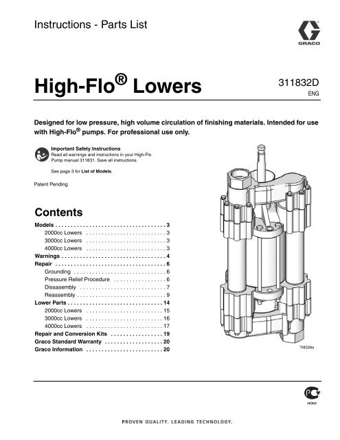
<strong>Instructions</strong> - <strong>Parts</strong> <strong>List</strong><strong>High</strong>-<strong>Flo</strong> ® <strong>Lowers</strong><strong>311832D</strong>ENGDesigned for low pressure, high volume circulation of finishing materials. Intended for usewith <strong>High</strong>-<strong>Flo</strong> ® pumps. For professional use only.Important Safety <strong>Instructions</strong>Read all warnings and instructions in your <strong>High</strong>-<strong>Flo</strong>Pump manual 311831. Save all instructions.See page 3 for <strong>List</strong> of Models.Patent PendingContentsModels . . . . . . . . . . . . . . . . . . . . . . . . . . . . . . . . . . . . 32000cc <strong>Lowers</strong> . . . . . . . . . . . . . . . . . . . . . . . . . . 33000cc <strong>Lowers</strong> . . . . . . . . . . . . . . . . . . . . . . . . . . 34000cc <strong>Lowers</strong> . . . . . . . . . . . . . . . . . . . . . . . . . . 3Warnings . . . . . . . . . . . . . . . . . . . . . . . . . . . . . . . . . . 4Repair . . . . . . . . . . . . . . . . . . . . . . . . . . . . . . . . . . . . 6Grounding . . . . . . . . . . . . . . . . . . . . . . . . . . . . . . 6Pressure Relief Procedure . . . . . . . . . . . . . . . . . 6Dissasembly . . . . . . . . . . . . . . . . . . . . . . . . . . . . 7Reassembly . . . . . . . . . . . . . . . . . . . . . . . . . . . . . 9Lower <strong>Parts</strong> . . . . . . . . . . . . . . . . . . . . . . . . . . . . . . . 142000cc <strong>Lowers</strong> . . . . . . . . . . . . . . . . . . . . . . . . . 153000cc <strong>Lowers</strong> . . . . . . . . . . . . . . . . . . . . . . . . . 164000cc <strong>Lowers</strong> . . . . . . . . . . . . . . . . . . . . . . . . . 17Repair and Conversion Kits . . . . . . . . . . . . . . . . . 19<strong>Graco</strong> Standard Warranty . . . . . . . . . . . . . . . . . . . 20<strong>Graco</strong> Information . . . . . . . . . . . . . . . . . . . . . . . . . 20TI8339a
ModelsModels2000cc <strong>Lowers</strong>Model No. Series Material Size (cc)Maximum PumpWorking Pressurepsi (MPa, bar)RodMaterialCylinderMaterialFittingStyle243731 E CST 2000 500 (3.5, 35) Chromex Chrome NPT 15243734 E SST 2000 500 (3.5, 35) Chromex Chrome BSPP 15243771 E SST 2000 500 (3.5, 35) Chromex Chrome NPT 15<strong>Parts</strong>Page3000cc <strong>Lowers</strong>Model No. Series Material Size (cc)Maximum PumpWorking Pressurepsi (MPa, bar)RodMaterialCylinderMaterialFittingStyle243732 E CST 3000 440 (3.0, 30) Chromex Chrome NPT 16243735 E SST 3000 440 (3.0, 30) Chromex Chrome BSPP 16243772 E SST 3000 440 (3.0, 30) Chromex Chrome NPT 16<strong>Parts</strong>Page4000cc <strong>Lowers</strong>Model No. Series Material Size (cc)Maximum PumpWorking Pressurepsi (MPa, bar)RodMaterialCylinderMaterialFittingStyle243733 E CST 4000 330 (2.3, 23) Chromex Chrome NPT 17243736 E SST 4000 330 (2.3, 23) Chromex Chrome BSPP 17243773 E SST 4000 330 (2.3, 23) Chromex Chrome NPT 17<strong>Parts</strong>Page<strong>311832D</strong> 3
WarningsWARNINGMOVING PARTS HAZARDMoving parts can pinch or amputate fingers and other body parts.• Keep clear of moving parts.• Do not operate equipment with protective guards or covers removed.• Pressurized equipment can start without warning. Before checking, moving, or servicing equipment,follow the Pressure Relief Procedure in this manual. Disconnect power or air supply.TOXIC FLUID OR FUMES HAZARDToxic fluids or fumes can cause serious injury or death if splashed in the eyes or on skin, inhaled, orswallowed.• Read MSDS’s to know the specific hazards of the fluids you are using.• Store hazardous fluid in approved containers, and dispose of it according to applicable guidelines.• Always wear impervious gloves when spraying or cleaning equipment.PERSONAL PROTECTIVE EQUIPMENTYou must wear appropriate protective equipment when operating, servicing, or when in the operatingarea of the equipment to help protect you from serious injury, including eye injury, inhalation of toxicfumes, burns, and hearing loss. This equipment includes but is not limited to:• Protective eyewear• Clothing and respirator as recommended by the fluid and solvent manufacturer• Gloves• Hearing protection<strong>311832D</strong> 5
RepairRepairGroundingThe equipment must be grounded. Grounding reducesthe risk of static and electric shock by providing anescape wire for the electrical current due to static buildup or in the event of a short circuit.Pump: use a ground wire and clamp. Remove the greenground screw (Z) from the bottom of the air motor. Insertthe screw through the loop on the end of the ground wire(Y) and reattach the screw to the air motor. Connect theground clamp to a true earth ground. See FIG. 1.Fluid supply container: follow local code.Object being sprayed: follow local code.Solvent pails used when flushing: follow local code.Use only conductive metal pails, placed on a groundedsurface. Do not place the pail on a nonconductive surface,such as paper or cardboard, which interruptsgrounding continuity.To maintain grounding continuity when flushing orrelieving pressure: hold metal part of the spray gunfirmly to the side of a grounded metal pail, then triggerthe gun.Pressure Relief ProcedureZY1. Engage trigger lock.2. Air-Powered Pumps only: Close the bleed-typemaster air valve.Hydraulic-Powered Pumps only: Close the hydraulicsupply line valve first, then the return line valve.FIG. 1TI8250aAir and fluid hoses: use only electrically conductivehoses with a maximum of 500 ft. (150 m) combinedhose length to ensure grounding continuity. Check theelectrical resistance of hoses. If total resistance toground exceeds 29 megohms, replace hose immediately.Air compressor: follow manufacturer’s recommendations.Hydraulic power supply: follow manufacturer’s recommendations.3. Disengage the trigger lock.4. Hold a metal part of the gun firmly to a groundedmetal pail. Trigger the gun to relieve pressure.5. Engage the trigger lock.6. Open all fluid drain valves in the system, having awaste container ready to catch drainage. Leavedrain valve(s) open until you are ready to sprayagain.7. If you suspect the spray tip or hose is clogged orthat pressure has not been fully relieved after followingthe steps above, VERY SLOWLY loosen tipguard retaining nut or hose end coupling to relieveSurge tank: use a ground wire and clamp.Spray gun: ground through a connection to a properlygrounded fluid hose and pump.6 <strong>311832D</strong>
Repairpressure gradually, then loosen completely. Clearhose or tip obstruction.CAUTIONHydraulic-Powered Pumps only: When shutting downthe hydraulic system, always shut off the hydraulicsupply line shutoff valve first, and then the return lineshutoff valve to prevent overpressurizing the motor orits seals. When starting the hydraulic system, openthe return line shutoff valve first.Disassembly• The following repair procedure can be used forany HIGH FLO model pump. The referencenumbers used in the text and illustrations correspondto all of the displacement pump partsdrawings.• Packing repair kits are available for each pump.<strong>Parts</strong> included in the pump seal repair kit aremarked with an asterisk in the text (for example,16*). <strong>Parts</strong> included in the throat packingkit are marked with a symbol (for example,39†). Conversion kits are also available. Seepage 31. Use all the new parts in the kits for thebest results.• This pump is easiest to repair when left in thePart No. 218742 accessory pump stand anddisassembled as instructed. For repair at aremote location, have another pump standavailable.• When reassembling, apply anti-seize lubricant222955 on the threads of the piston shaft (29)and piston (23).1. Use a 13 mm socket wrench to loosen and removethe twelve capscrews (2) and lockwashers (3) onthe outlet manifold (1). See FIG. 9.2. Lift the manifold (1) off the outlet valve housing (5)and remove the ball guides (14), balls (13), seats(17) and seals (15). Remove the o-ring (16) from theseats (17).Seat Puller Kit 220384 is available to make removalof the seats from the manifolds easier. See FIG. 2.CAUTIONBe careful not to drop or damage the balls (13) orseats (17). A damaged ball or seat cannot seal properlyand the pump will leak. The outlet valve seats(17) can be reversed to provide longer use of the seat.Seat Puller Kit 220384FIG. 2ZScrew bolt (X, Part 108481) into SeatPuller (Y, Part 181630).YPosition Seat Puller (Y) under the seat(Ref. 22 on pages 13, 14, 15) by slippingit through at an angle.Place Seat Puller (Z, Part 181629) ontop of seat. Turn bolt (X) to pull theseat out.3. Remove the nuts (8), lockwashers (7), and six cylindercapscrews (4). Loosen the wet cup (12). Lift offthe outlet valve housing (5). See Manual 311831.XXYS014144. Lift the riser tubes (20) and cylinder (27) off the inletvalve housing (6). The piston assembly may stay in<strong>311832D</strong> 7
Repairthe cylinder. Remove the seals (21 and 28) from theinlet and outlet housings (5, 6). See FIG. 9.Tap on the valve housings with a plastic mallet anduse a slight rocking motion to help loosen andremove the cylinder and tubes.5. Screw out the wet cup (12). Using a small,flat-bladed screw driver pry out the cartridge gland(32) using the groove on the outer surface. Removeremaining packings (31,35) and glands (30, 42)from the nut. See FIG. 3.6. Unscrew and remove the three pump stand bolts(D). See Manual 311831. Lift the inlet valve assemblyoff the stand. Place the inlet valve housing (6)face down on a protected surface.7. Use a 13 mm socket wrench to loosen and removethe twelve capscrews (2) and lockwashers (3) fromthe inlet manifold (1). See FIG. 9.8. Lift the manifold (1) off the inlet valve housing (6)and remove the seats (17 and 22). Remove theo-ring (16) from the seats.CAUTIONIf the pressure relief valve in the inlet seat (22) isclogged or filled with material, soak the inlet seat in acompatible solvent. Make sure all material residue iscleaned from the ball and seat area.If the relief valve cannot be thoroughly cleaned so thatthe ball and spring are free to move, replace the seat(22).9. Inspect the pressure relief valve in the fluid inlet seat(22) to make sure it is not clogged. Press down onthe valve's ball to see if the ball and spring are freeto move. See the detail in FIG. 9.12CAUTIONBe careful not to drop or damage the balls (13) orseats (17 or 22). A damaged ball or seat cannot sealproperly and the pump will leak. One inlet valve seat(17) can be reversed to provide longer use of the seat.However, the fluid inlet seat (22) contains a pressurerelief valve and is not reversible. See the detail in FIG.9 for proper orientation.25313035 2421 3135 132341 Lips of v-packings face down.2 Lips of v-packings face up.FIG. 3TI8393a210. Remove the balls (13), ball guides (14) and seals(15) from the inlet valve housing (6).11. Push the piston assembly through the cylinder justenough to expose the piston (23) flats. Secure thepiston flats in a vise. Use a plastic mallet to tap thecylinder (27) up and off the piston assembly.See FIG. 4 for steps 12-16.12. Loosen the piston nut (26). Use Tool Kit 220385 toremove the piston shaft (29) and piston nut (26).See FIG. 5. Remove the piston nut o-ring (18) ando-ring retainer (43) from the shaft. Remove the plate(25) and the seal (24) from the piston (23). See FIG.4.13. Inspect the piston shaft (29). If it is damaged or thesurface is scored, replace it.8 <strong>311832D</strong>
Repair14. Clean all piston parts and the cylinder thoroughly ina compatible solvent. Inspect the inner surface ofthe cylinder for scoring, and replace it if necessary.A scored cylinder will quickly damage the packings.Tool Kit 220385Tighten the tool on the widest part of the shaft (29).Grip the tool with a wrench and unscrew the shaft.Reassembly15. Lubricate the new piston seal (24*) and install it onthe piston.2916. Install the piston plate (25) with the beveled edgefacing away from the piston seal. See FIG. 4. ®124FIG. 42612344329 2181925TI0219Torque to 270-284 N•m (200-210 ft-lb).Apply Loctite ® 263 or 2760 (red) to threads.Allow to cure at least 12 hours before use.Lubricate.Apply anti-seize lubricant 222955 to the faceof piston nut.24*23 3FIG. 517. Install o-ring retainer (43). Lubricate o-ring (18) andslide it on over the threads of piston shaft. ApplyLoctite 263 or 2760 (red) to the piston nut (26)threads and the piston rod. Screw the nut snuglyagainst the o-ring retainer (43). Allow to cure for atleast 12 hours before use. Apply anti-seize lubricant222955 to the bottom face of the piston nut (26).Assemble o-ring (19) and install in the groove on thepiston nut. Screw rod (29) into piston (23) until snug.Tighten piston nut (26) to 270-284 N•m. (200-210ft-lb).18. Remove the piston assembly from the vise, but donot lay it down on its side; doing so may damagethe seal.See FIG. 6 for step 19.0141319. Carefully and evenly guide the seal and the pistoninto the cylinder. The piston seal and piston mayneed to be tipped at an angle and the exposed,leading lip of the seal tapped into the cylinder with aplastic mallet. After the seal lip has entered the cylinderuse an arbor press or tap the bottom of thepiston assembly lightly with a plastic mallet to slidethe piston assembly into the cylinder. Before pressing,ensure the piston seal lips are started into thecylinder. See FIG. 6.<strong>311832D</strong> 9
Repair20. Clean the remaining pump parts in a compatible solvent.23122429275302 3135 242TI02211 3135 132FIG. 61 Do not damage edges of seal.A34TI8393a21Lips of v-packings face down.See FIG. 7 for steps 21 and 22.2Lips of v-packings face up.FIG. 721. Lubricate three new throat packings (two - 31†) and(one - 35†) and the male gland (30†) with lightgrease. Holding the wet cup (12), drop the gland(30†) into the wet cup so that the lips face up. Alternatelyset the three v-packings with the lips facingup into the wet cup one at a time, starting with 31†,followed by 35†, and ending with 31†. See FIG. 7.22. Lubricate the female gland (42†) well and place it inthe wet cup. Lubricate seven new throat packings(four - 31†) and (three - 35†) with light grease. Alternatelyset the seven v-packings with the lips facingdown into the wet cup one at a time, starting with(31†), followed by (35†), and ending with (31†).Lightly grease gland assembly (32) and press fit intowetcup (12) until you feel the o-ring (A) snap intogroove. Place lubricated o-ring (34) into groove onthe face of the gland assembly (32). See FIG. 7.See FIG. 9 for steps 23-25 unless otherwise indicated.23. Loosely screw the wet cup (12) into the outlet valvehousing (5). See FIG. 9.24. Lubricate and install the new o-rings (16*) aroundeach of the four ball seats (17 and 22).CAUTIONThe orientation of the ball valves in the inlet and outletvalve housings is critical. Install the parts of the ballvalve exactly as instructed and refer to FIG. 9. Ifinstalled incorrectly, the pump will not operate.25. Place the inlet valve housing (6) on a flat surfacewith the ball valve openings facing up. Lubricate theseals (15*) and set them into each side of the inletvalve housing.10 <strong>311832D</strong>
Repair64402412943182326193303135311122524425423313531353135311119632345141528132221171620132824121141401Apply lubricant to all packings.23Apply thread sealant.Torque to 200-210 ft-lbs (270-285 N•m).TI8338a4Torque to18-20 ft-lbs (24-27 N•m).5Torque to 60-65 ft-lbs (81-88 N•m).6Torque to 50 ft-lbs (67 N•m), then back offand re-torque to 20-25 ft-lbs (27-34 N•m).FIG. 912 <strong>311832D</strong>
Repair29124, 7, 8141314151751628211718261625TI8393a22024431962321141315221611517162, 3FIG. 10TI8393a<strong>311832D</strong> 13
Lower <strong>Parts</strong>Lower <strong>Parts</strong>2000cc Lower parts list, see page 153000cc Lower parts list, see page 164000cc Lower parts list, see page 173031353140231124129431826192524423135313531353142311963234528211714151322162028132214140TI8338a14 <strong>311832D</strong>
Lower <strong>Parts</strong>3000cc <strong>Lowers</strong>Part No. 243732, Series E, Carbon SteelPart No. 243735, Series E, Stainless SteelPart No. 243772, Series E, Stainless SteelLowerRef. Description 243732 243735 243772 Qty1 MANIFOLD 180520 2MANIFOLD 193203 193203 22 CAPSCREW, hex hd; M8 x 1.25; sst 107554 107554 107554 243 WASHER, flat; 8.4 mm; sst 111003 111003 111003 244 CAPSCREW, hex hd; M12 x 1.25; sst 107553 107553 107553 65 HOUSING, outlet; cst 180522 1HOUSING, outlet; sst 180524 180524 16 HOUSING, inlet; cst 180521 1HOUSING, inlet; sst 180523 180523 17 WASHER, lock 108792 108792 108792 68 NUT, M8 x 1.25; sst 107538 107538 107538 69 SCREW, drive 103972 103972 103972 412 CUP, wet, ass’y 254966 254966 254966 113 BALL, intake; 2 in. (51 mm) dia.; sst 110294 110294 110294 414 GUIDE, ball; sst 180509 180509 180509 415 SEAL, UHMWPE 180761 180761 180761 416 PACKING, o-ring; PTFE 107545 107545 107545 417 SEAT, valve, sst 180529 180529 180529 318 PACKING, o-ring; PTFE encapsulated 115929 115929 115929 1fluoroselastomer19 PACKING, o-ring; PTFE 115930 115930 115930 120 TUBE, riser 180530 180530 180530 221 SEAL, UHMWPE 180760 180760 180760 422 SEAT, valve; relief 237572 237572 237572 123 PISTON, pump 196263 196263 196263 124 SEAL, piston; UHMWPE 196233 196233 196233 125 PLATE, retaining 196264 196264 196264 126 NUT, jam 196243 196243 196243 127 CYLINDER, pump 180498 180498 180498 128 SEAL, UHMWPE 180758 180758 180758 229 SHAFT, piston 16A677 16A677 16A677 130 GLAND, packing, male 198360 198360 198360 131 V-PACKING, UHMWPE 180641 180641 180641 632 GLAND, cartridge 243839 243839 243839 133▲ TAG, warning 196685 196685 196685 134 O-RING, PTFE 109213 109213 109213 135 V-PACKING, leather 15J057 15J057 15J057 440 FITTING, 2 in. npt, 2 in. bspp 196321 241 SEAL, PTFE 193424 242 GLAND, packing, female 196216 196216 196216 1▲ Replacement Danger and Warning labels, tags, and cards are available at no cost.* <strong>Parts</strong> included in Seal Repair Kit (purchase separately). See page 18.† <strong>Parts</strong> included in Throat Packing Repair Kit (purchase separately). See page 18.16 <strong>311832D</strong>
Lower <strong>Parts</strong>18 <strong>311832D</strong>
Repair and Conversion KitsRepair and Conversion KitsUse Only Genuine <strong>Graco</strong> <strong>Parts</strong> and AccessoriesPiston Seal Repair Kit 243727For Displacement Pumps 243731 & 243734.Ref. Part No. Description Qty15 180761 SEAL; UHMWPE 416 107545 O-RING; PTFE 418 115929 PACKING, O–RING 119 115930 PACKING, O–RING 121 180760 SEAL; UHMWPE 424 196232 SEAL, piston; UHMWPE 128 180759 SEAL; UHMWPE 2Piston Seal Repair Kit 243728For Displacement Pump 243732 & 243735.Ref. Part No. Description Qty15 180761 SEAL; UHMWPE 416 107545 O-RING; PTFE 418 115929 PACKING, O–RING 119 115930 PACKING, O–RING 121 180760 SEAL; UHMWPE 424 196233 SEAL, piston; UHMWPE 128 180758 SEAL; UHMWPE 2Piston Seal Repair Kit 243729For Displacement Pumps 243733 & 243736.Ref. Part No. Description Qty15 180761 SEAL; UHMWPE 416 107545 O-RING; PTFE 4 418 115929 PACKING, O–RING 119 115930 PACKING, O–RING 121 180760 SEAL; UHMWPE 424 196234 SEAL, piston; UHMWPE 128 180757 SEAL; UHMWPE 2UHMWPE/Leather Throat PackingRepair Kit 243671.For all pumps.Ref. Part No. Description Qty30 198360 GLAND, packing, male 131 180641 V–PACKING, UHMWPE 632 243839 GLAND, packing male 134 109213 O–RING, PTFE 135 15J057 V-PACKING, leather 442 196216 GLAND, packing female 1Coupling Jaw Kit 273026.For all pumps.Ref. Part No. Description Qty184129 COLLAR, coupling 2186925 NUT, coupling 129 16A677 SHAFT, piston 1PTFE/Leather Throat Packing Repair Kit 243672.For all pumps.Ref. Part No. Description Qty30 198360 GLAND, packing, male 131 190298 V–PACKING, PTFE 632 243839 GLAND, packing, male 134 109213 O–RING, PTFE 135 15J057 V-PACKING, leather 442 196216 GLAND, packing, female 1Triple Lip_ Throat Conversion Kit 243673.For all pumps.Part No. Description Qty115906 O–RING 1196240 BEARING 1243674 SEAL, Throat 1Piston Seal Conversion Kit 235855For Displacement Pump 243732 & 243735.Ref. Part No. Description Qty15 180761 SEAL; UHMWPE 416 107545 O–RING; PTFE 418 115929 PACKING, O–RING 119 115930 PACKING, O–RING 121 180760 SEAL; UHMWPE 424 112037 SEAL; unfilled PTFE 128 180758 SEAL; UHMWPE 2Piston Seal Conversion Kit 235856For Displacement Pumps 243731 & 243734.Ref. Part No. Description Qty15 180761 SEAL; UHMWPE 416 107545 O-RING; PTFE 418 115929 PACKING, O–RING 119 115930 PACKING, O–RING 121 180760 SEAL; UHMWPE 424 112038 SEAL; unfilled PTFE 128 180759 SEAL; UHMWPE 2Piston Seal Conversion Kit 235854For Displacement Pumps 243733 & 243736.Ref. Part No. Description Qty15 180761 SEAL; UHMWPE 416 107545 O-RING; PTFE 418 115929 PACKING, O–RING 119 115930 PACKING, O–RING 121 180760 SEAL; UHMWPE 424 112036 SEAL; unfilled PTFE 128 180757 SEAL; UHMWPE 2<strong>311832D</strong> 19
<strong>Graco</strong> Standard Warranty<strong>Graco</strong> warrants all equipment referenced in this document which is manufactured by <strong>Graco</strong> and bearing its name to be free from defects inmaterial and workmanship on the date of sale to the original purchaser for use. With the exception of any special, extended, or limited warrantypublished by <strong>Graco</strong>, <strong>Graco</strong> will, for a period of twelve months from the date of sale, repair or replace any part of the equipment determined by<strong>Graco</strong> to be defective. This warranty applies only when the equipment is installed, operated and maintained in accordance with <strong>Graco</strong>’s writtenrecommendations.This warranty does not cover, and <strong>Graco</strong> shall not be liable for general wear and tear, or any malfunction, damage or wear caused by faultyinstallation, misapplication, abrasion, corrosion, inadequate or improper maintenance, negligence, accident, tampering, or substitution ofnon-<strong>Graco</strong> component parts. Nor shall <strong>Graco</strong> be liable for malfunction, damage or wear caused by the incompatibility of <strong>Graco</strong> equipment withstructures, accessories, equipment or materials not supplied by <strong>Graco</strong>, or the improper design, manufacture, installation, operation ormaintenance of structures, accessories, equipment or materials not supplied by <strong>Graco</strong>.This warranty is conditioned upon the prepaid return of the equipment claimed to be defective to an authorized <strong>Graco</strong> distributor for verification ofthe claimed defect. If the claimed defect is verified, <strong>Graco</strong> will repair or replace free of charge any defective parts. The equipment will be returnedto the original purchaser transportation prepaid. If inspection of the equipment does not disclose any defect in material or workmanship, repairs willbe made at a reasonable charge, which charges may include the costs of parts, labor, and transportation.THIS WARRANTY IS EXCLUSIVE, AND IS IN LIEU OF ANY OTHER WARRANTIES, EXPRESS OR IMPLIED, INCLUDING BUT NOT LIMITEDTO WARRANTY OF MERCHANTABILITY OR WARRANTY OF FITNESS FOR A PARTICULAR PURPOSE.<strong>Graco</strong>’s sole obligation and buyer’s sole remedy for any breach of warranty shall be as set forth above. The buyer agrees that no other remedy(including, but not limited to, incidental or consequential damages for lost profits, lost sales, injury to person or property, or any other incidental orconsequential loss) shall be available. Any action for breach of warranty must be brought within two (2) years of the date of sale.GRACO MAKES NO WARRANTY, AND DISCLAIMS ALL IMPLIED WARRANTIES OF MERCHANTABILITY AND FITNESS FOR APARTICULAR PURPOSE, IN CONNECTION WITH ACCESSORIES, EQUIPMENT, MATERIALS OR COMPONENTS SOLD BUT NOTMANUFACTURED BY GRACO. These items sold, but not manufactured by <strong>Graco</strong> (such as electric motors, switches, hose, etc.), are subject tothe warranty, if any, of their manufacturer. <strong>Graco</strong> will provide purchaser with reasonable assistance in making any claim for breach of thesewarranties.In no event will <strong>Graco</strong> be liable for indirect, incidental, special or consequential damages resulting from <strong>Graco</strong> supplying equipment hereunder, orthe furnishing, performance, or use of any products or other goods sold hereto, whether due to a breach of contract, breach of warranty, thenegligence of <strong>Graco</strong>, or otherwise.FOR GRACO CANADA CUSTOMERSThe Parties acknowledge that they have required that the present document, as well as all documents, notices and legal proceedings entered into,given or instituted pursuant hereto or relating directly or indirectly hereto, be drawn up in English. Les parties reconnaissent avoir convenu que larédaction du présente document sera en Anglais, ainsi que tous documents, avis et procédures judiciaires exécutés, donnés ou intentés, à la suitede ou en rapport, directement ou indirectement, avec les procédures concernées.<strong>Graco</strong> InformationFor the latest information about <strong>Graco</strong> products, visit www.graco.com.TO PLACE AN ORDER, contact your <strong>Graco</strong> distributor or call to identify the nearest distributor.Phone: 612-623-6921 or Toll Free: 1-800-328-0211 Fax: 612-378-3505All written and visual data contained in this document reflects the latest product information available at the time of publication.<strong>Graco</strong> reserves the right to make changes at any time without notice.Original instructions. This manual contains English. MM 311832<strong>Graco</strong> Headquarters: MinneapolisInternational Offices: Belgium, China, Japan, KoreaGRACO INC. P.O. BOX 1441 MINNEAPOLIS, MN 55440-1441Copyright 2006, <strong>Graco</strong> <strong>Inc</strong>. is registered to ISO 9001www.graco.comRevised 02/2011


