332312A - E4-5 Meter-Mix Dispense System, Operation ... - Graco Inc.
332312A - E4-5 Meter-Mix Dispense System, Operation ... - Graco Inc.
332312A - E4-5 Meter-Mix Dispense System, Operation ... - Graco Inc.
Create successful ePaper yourself
Turn your PDF publications into a flip-book with our unique Google optimized e-Paper software.
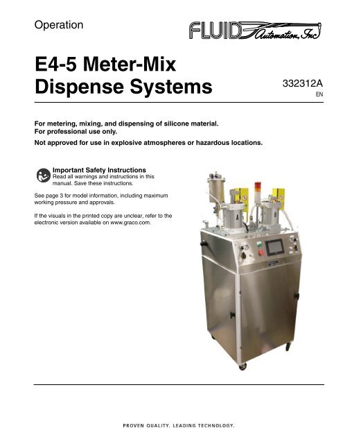
<strong>Operation</strong><strong>E4</strong>-5 <strong>Meter</strong>-<strong>Mix</strong><strong>Dispense</strong> <strong>System</strong>s<strong>332312A</strong>ENFor metering, mixing, and dispensing of silicone material.For professional use only.Not approved for use in explosive atmospheres or hazardous locations.Important Safety InstructionsRead all warnings and instructions in thismanual. Save these instructions.See page 3 for model information, including maximumworking pressure and approvals.If the visuals in the printed copy are unclear, refer to theelectronic version available on www.graco.com.
ContentsContentsContents . . . . . . . . . . . . . . . . . . . . . . . . . . . . . . . . . . 2Related Manuals . . . . . . . . . . . . . . . . . . . . . . . . . . . 2Models . . . . . . . . . . . . . . . . . . . . . . . . . . . . . . . . . . . 3Warnings . . . . . . . . . . . . . . . . . . . . . . . . . . . . . . . . . 4Component Identification . . . . . . . . . . . . . . . . . . . . 7General Information . . . . . . . . . . . . . . . . . . . . . . . . 8Pressure Settings . . . . . . . . . . . . . . . . . . . . . . . . 8Low Level Proximity Switches . . . . . . . . . . . . . . . 9Platen - Colorant Tank (Optional) . . . . . . . . . . . . 9Solvents . . . . . . . . . . . . . . . . . . . . . . . . . . . . . . . 9Screen Navigation . . . . . . . . . . . . . . . . . . . . . . . . . 10Screen Identification . . . . . . . . . . . . . . . . . . . . . . . 14Installation . . . . . . . . . . . . . . . . . . . . . . . . . . . . . . . 25Setup . . . . . . . . . . . . . . . . . . . . . . . . . . . . . . . . . . . . 28Startup . . . . . . . . . . . . . . . . . . . . . . . . . . . . . . . . . . 31Shutdown . . . . . . . . . . . . . . . . . . . . . . . . . . . . . . . . 32Pressure Relief Procedure . . . . . . . . . . . . . . . . . . 33<strong>Dispense</strong> Head Solenoid . . . . . . . . . . . . . . . . . . 33Bleed Ball Valves . . . . . . . . . . . . . . . . . . . . . . . . 33<strong>Operation</strong> . . . . . . . . . . . . . . . . . . . . . . . . . . . . . . . . 34Pail Change-Over . . . . . . . . . . . . . . . . . . . . . . . 34Testing Procedures . . . . . . . . . . . . . . . . . . . . . . . . 36Pump Testing . . . . . . . . . . . . . . . . . . . . . . . . . . . 36Ratio Testing . . . . . . . . . . . . . . . . . . . . . . . . . . . 36Troubleshooting . . . . . . . . . . . . . . . . . . . . . . . . . . . 38Common Problems . . . . . . . . . . . . . . . . . . . . . . 38String Pot Calibration . . . . . . . . . . . . . . . . . . . . . 40Schematics . . . . . . . . . . . . . . . . . . . . . . . . . . . . . . . 41Dimensions . . . . . . . . . . . . . . . . . . . . . . . . . . . . . . . 46Technical Data . . . . . . . . . . . . . . . . . . . . . . . . . . . . 47<strong>Graco</strong> Standard Warranty . . . . . . . . . . . . . . . . . . . 48Related ManualsManual332313Description<strong>E4</strong>-5 <strong>Meter</strong>-<strong>Mix</strong> <strong>Dispense</strong> <strong>System</strong>s,Instructions-Parts2 <strong>332312A</strong>
ModelsModelsPart No.<strong>E4</strong>-5MMaximum WorkingPressuresRefer to TechnicalData, page 47DescriptionPLC Encoder Controlled, 1:1 to 2:1 Variable Ratio, 5-Gallon <strong>Meter</strong> <strong>Mix</strong>Machine. Machine uses B443M Base Pumps with check assemblies forenhanced control. Machine has 3 in. (7.6 cm) ram air cylinders andEnclosed Cabinet Frame with Casters.<strong>332312A</strong> 3
WarningsWarningsThe following warnings are for the setup, use, grounding, maintenance, and repair of this equipment. The exclamationpoint symbol alerts you to a general warning and the hazard symbols refer to procedure-specific risks. Whenthese symbols appear in the body of this manual or on warning labels, refer back to these Warnings. Product-specifichazard symbols and warnings not covered in this section may appear throughout the body of this manual whereapplicable.WARNINGELECTRIC SHOCK HAZARDThis equipment must be grounded. Improper grounding, setup, or usage of the system can cause electricshock.• Turn off and disconnect power cord before servicing equipment.• Connect only to grounded electrical outlets.• Use only 3-wire extension cords.• Ensure ground prongs are intact on power and extension cords.• Do not expose to rain. Store indoorsTOXIC FLUID OR FUMES HAZARDToxic fluids or fumes can cause serious injury or death if splashed in the eyes or on skin, inhaled, or swallowed.• Read MSDSs to know the specific hazards of the fluids you are using.• Store hazardous fluid in approved containers, and dispose of it according to applicable guidelines.• Always wear chemically impermeable gloves when spraying, dispensing, or cleaning equipment.PERSONAL PROTECTIVE EQUIPMENTWear appropriate protective equipment when in the work area to help prevent serious injury, includingeye injury, hearing loss, inhalation of toxic fumes, and burns. This protective equipment includes but is notlimited to:• Protective eyewear, and hearing protection.• Respirators, protective clothing, and gloves as recommended by the fluid and solvent manufacturerSKIN INJECTION HAZARDHigh-pressure fluid from dispensing device, hose leaks, or ruptured components will pierce skin. Thismay look like just a cut, but it is a serious injury that can result in amputation. Get immediate surgicaltreatment.• Engage trigger lock when not dispensing.• Do not point dispensing device at anyone or at any part of the body.• Do not put your hand over the fluid outlet.• Do not stop or deflect leaks with your hand, body, glove, or rag.• Follow the Pressure Relief Procedure when you stop dispensing and before cleaning, checking, orservicing equipment.• Tighten all fluid connections before operating the equipment.• Check hoses and couplings daily. Replace worn or damaged parts immediately4 <strong>332312A</strong>
WarningsWARNINGFIRE AND EXPLOSION HAZARDFlammable fumes, such as solvent and paint fumes, in work area can ignite or explode. To help preventfire and explosion:• Use equipment only in well ventilated area.• Eliminate all ignition sources; such as pilot lights, cigarettes, portable electric lamps, and plastic dropcloths (potential static arc).• Keep work area free of debris, including solvent, rags and gasoline.• Do not plug or unplug power cords, or turn power or light switches on or off when flammable fumesare present.• Ground all equipment in the work area. See Grounding instructions.• Use only grounded hoses.• Hold gun firmly to side of grounded pail when triggering into pail. Do not use pail liners unless theyare antistatic or conductive.• Stop operation immediately if static sparking occurs or you feel a shock. Do not use equipmentuntil you identify and correct the problem.• Keep a working fire extinguisher in the work area.EQUIPMENT MISUSE HAZARDMisuse can cause death or serious injury.• Do not operate the unit when fatigued or under the influence of drugs or alcohol.• Do not exceed the maximum working pressure or temperature rating of the lowest rated system component.See Technical Data in all equipment manuals.• Use fluids and solvents that are compatible with equipment wetted parts. See Technical Data in allequipment manuals. Read fluid and solvent manufacturer’s warnings. For complete information aboutyour material, request MSDS from distributor or retailer.• Turn off all equipment and follow the Pressure Relief Procedure when equipment is not in use.• Check equipment daily. Repair or replace worn or damaged parts immediately with genuine manufacturer’sreplacement parts only.• Do not alter or modify equipment. Alterations or modifications may void agency approvals and createsafety hazards.• Make sure all equipment is rated and approved for the environment in which you are using it.• Use equipment only for its intended purpose. Call your distributor for information.• Route hoses and cables away from traffic areas, sharp edges, moving parts, and hot surfaces.• Do not kink or over bend hoses or use hoses to pull equipment.• Keep children and animals away from work area.• Comply with all applicable safety regulations.<strong>332312A</strong> 5
WarningsWARNINGMOVING PARTS HAZARDMoving parts can pinch, cut or amputate fingers and other body parts.• Keep clear of moving parts.• Do not operate equipment with protective guards or covers removed.• Pressurized equipment can start without warning. Before checking, moving, or servicing equipment,follow the Pressure Relief Procedure and disconnect all power sources.SPLATTER HAZARDHot or toxic fluid can cause serious injury if splashed in the eyes or on skin. During blow off of platen,splatter may occur.• Use minimum air pressure when removing platen from drum.6 <strong>332312A</strong>
Component IdentificationComponent IdentificationABCDEFGHJStack Light Indicator(Red = Fault, Amber = Pump Started)Main Air Regulator and GaugeOperator Interface PanelRam Air Regulator and GaugeRam Control ValveDrum Blow-off Control ValvePail ShelfBase Pump(B443M Standard)Pump EncoderKLMNPRSTBleed Ball ValveMaterial Ball ValveColorant TankLow Level Proximity SensorString Pot Sensor (Optional)Pump Bleed ValveControl Power ButtonStop ButtonMJALDBEPRFCSTNHKGFIG. 1: <strong>E4</strong>-5<strong>332312A</strong> 7
General InformationGeneral InformationPressure SettingsRam AirFor low durometer material (
General InformationLow Level Proximity SwitchesThe adjustable low level proximity switches aredesigned to stop the metering pump when the materialin either pail runs low. The proximity switches are to preventthe machine from pumping air into the materiallines. When the ram is lowered and the fault cleared, thepump can be restarted.Platen - Colorant Tank (Optional)The platen is recommended for materials that are notpourable or self leveling. There is a small plastic platenshipped with each colorant tank. If the colorant is inpaste form, the platen is placed on top of the colorantand should be removed BEFORE filling the tank. If thecolorant that is being used flows easily the platen shouldnot be used because it will sink and block the tank outlet.SolventsThese are rarely used with modern 1:1 silicones. Forcleaning, methylene chloride or white spirits solvent areused. Methylene chloride is recommended because it isnon-flammable.To avoid serious injury, do not use flammablesolvents for cleaning.<strong>332312A</strong> 9
Screen NavigationScreen Navigation10 <strong>332312A</strong>
Screen Navigation<strong>332312A</strong> 11
Screen Navigation12 <strong>332312A</strong>
Screen Navigation<strong>332312A</strong> 13
Screen IdentificationScreen IdentificationMode Select ScreenThe “Mode Select” Screen is the default screen on startup. It can be used to select an operating mode, control colorinjection, and navigate to other screens for setup and operation.The different modes can be used to:• <strong>Dispense</strong> material while monitoring the ratio• Take a sample ratio• Prime the pumps• Purge Material• Transfer material to another unit• Bring the pumps to their home positionNOTE: Refer to Schematics, page 41, for customer signal information.IconDescriptionExplains how to use the Mode Selections and the Color Injectors on the screen.Brings the pumps back to their home position. Pressing the “Start Pump” button on themonitor screen turns the pumps on. The machine will alert the user when in the eventthat it needs to be “rehomed.”Main dispensing mode. It will dispense material at a specified ratio as long as the “ScrewRotate Signal” is active. Pressing the “Start Pump” button on the monitor screen willallow the machine to look for that signal. The “ready” signal will activate in this modewhen the start pump is pressed.This mode will vary the ratio by a maximum of 5% to get the pails to empty out at thesame time. It is not attempting to maintain a 1:1 ratio. It will dispense material at a rationear 1:1 as long as the “Screw Rotate Signal” is active. Pressing the “Start Pump” buttonon the monitor screen will allow the machine to look for that signal. The “ready” signal willactivate in this mode when the start pump is pressed. Always check with the materialsupplier to verify material tolerances prior to using this mode.Purge Mode operates only one pump at a time. The button purges the injection and manifold/mixerassemblies with a single component of material. Contact your material supplierto determine which material is best for purging. Press the “Start Pump” button onthe monitor screen to allow the machine to operate. It will purge as long as the “ScrewRotate Signal” is active.14 <strong>332312A</strong>
Screen IdentificationIconDescriptionBefore starting to prime, decrease the regulated air pressure to 20 psi (140 kPa, 1.4 bar)- Reducing the pressure prevents pump cavitation. <strong>Inc</strong>rease as needed. Refer to Purgeand Prime the Pump, page 28, for details on purging the machine. The pump will startoperating as soon as the “Start Pump” button is pressed on the monitor screen once themode is allowed.Intended to check the ratio of the machine. The outlet valves will not open and faults willnot be generated. To check the ratio, refer to Ratio Testing, page 36. The pumps willactuate as soon as the “Start Pump” button is pressed on the monitor screen.Transfer Mode allows both pumps to operate independently. Typical applications for themode are for filling small cartridges individually or feeding the 600 series metering units.The pumps are active as soon as the “Start Pump” button is pressed on the monitorscreen.Navigates to the “Monitor Screen”.Navigates to the “Main Screen”.Navigates to view the alarm history of the machine.Toggles the color injector for the corresponding machine (1 or 2) on or off. The injectorworks with the “<strong>System</strong> Ready Bit”, and operates under the parameters on the PresetScreen.This is a banner that tells the user what mode the machine is in.This is a button that goes to a screen showing the software part numbers and revisions.<strong>332312A</strong> 15
Screen IdentificationMonitor ScreenThe “Monitor Screen” will be used most for dispensing material. Most of the fields on here are for feedback only. Thebottom row of buttons are used to navigate to other screens, while the buttons on the right side are used to controlthe pump.IconDescriptionDepending on what mode the machine is in, the button will either start the pump immediatelyor allow the pump to run and look for a “Screw Rotate Signal” to start pumping.Stop the pump from operating.Navigates to the “Main Screen”.Navigates to the “Mode Select Screen”.<strong>Meter</strong> Mode:The amount of travel for a pump can be regulated from 50-100% of its potential travel. Forexample: One pump may travel at 50% of its full capability while the other pump is traveling at100% capability. The system would be operating in a 1:2 ratio. This shows the preset percentageand the actual percentage of pump travel.Closed-Loop Mode:The actual percentage may vary from the preset by +/- 5%, which is always a 1:1 ratio.Always check the material supplier to verify material tolerances prior to using this mode.Some materials (self-bonding or self-bleeding grades) should not use this mode since atighter tolerance is needed.This field shows the position of each pump, and if they are moving in the up or down direction.This shows if the injector is on or off, and what percentage of colorant is making up the totalmixed material volume.This shows how many kilograms of material are left in the container.16 <strong>332312A</strong>
Screen IdentificationMain ScreenThe top row of buttons requires a password, the bottom row is accessible without a password. To enter a password,simply touch the blue box, and a keypad will appear. The default password is 0. Refer to the Presets Screen screen,page 20, for information on how to change the password.IconDescriptionThis screen allows the user to set how far the pumps are allowed to deviate from each other beforean alarm is set off. It also allows the user to set how many seconds the alarm sounds for, as well asto change the password.The system preset screen allows for configuring the HMI panel, and setting the communicationbaud rate.The preset screen gives access to the color injection properties, mixed material specific gravity,machine ratio, material container size, and pail monitor settings.The mode screen select gives control of the color injection system, and allows the user to changemodes of the machine.Navigates to the “Monitor Screen”.The I/O Table screen shows the user what inputs and what outputs on the PLC are active.<strong>332312A</strong> 17
Screen IdentificationFault Presets ScreenThe Fault Preset screen allows the user to:• Configure when errors are generated• Configure how long the alarm sounds for• Access to change the passwordThe Upstroke and Downstroke values are represented by encoder counts. The larger the number, the greater thespacing allowed before a fault will occur. For example, there are 30,000 counts in the 4.5 in. (11 cm) pump stroke, sothe default tolerance is a 0.45 in. (1 cm) difference. The default value is 3000.Each pump has its own presets to generate alarms. For example, when both pumps are traveling down, the A sidecan travel faster the B side by X amount, and the B side can travel faster the A side by Y amount. The same conceptapplies to traveling up.IconDescriptionExplains what the Pump Stroke Fault Presets represent and how to use them.Measured in encoder counts. This is how much further a specified pump may be travelingahead of the other pump in the up direction. For example, “A” Upstroke is how far the A pumpcan be ahead of the B pump when traveling up. The default is 3000.Measured in encoder counts. This is how much further a specified pump may be travelingahead of the other pump in the down direction. For example, “A” Downstroke is how far the Apump can be ahead of the B pump when traveling down. The default is 3000.This is how many seconds the alarm will sound when a fault is detected.Entering a password in this field changes the password for accessing protected screens.“On” disables any faults related to the color injector frequency from being generated.“Off” monitors the color injector for too few shots (uneven color) or too many shots per secondwhere the color injector will not be able to refill properly.18 <strong>332312A</strong>
Screen Identification<strong>System</strong> ScreenThe <strong>System</strong> Preset Screen allows the user to change the baud rate of the HMI communication. This adjustmentwould be needed if a replacement HMI was being installed on legacy equipment.IconDescriptionGives access to the HMI panel configuration. It is rare that normal machine operation will requireaccess to this.The PLC communication baud rate. The default is 19200, legacy PLCs communicate at 9600.<strong>332312A</strong> 19
Screen IdentificationPresets ScreenThe Preset Screen allows the user to make adjustments to settings directly related to dispensing material:• Color Injector Percent• Color Injector Shot Size• <strong>Mix</strong>ed Material Specific Gravity• Machine Ratio• Pail Monitor SettingsIcon DescriptionPercent of color to be injected with the amount of material being dispensed. There are separateeditable boxes for colors 1 and 2. If the entered value is too small, the field will turn yellow.Size of the shot being dispensed by each color injector. The shot size is adjustable mechanically,so test the shot size of each color individually. Refer to Adjust the Colorant InjectorShot Size, page 30.The Specific Gravity of the mixed material. Refer to the material data sheet supplied by thematerial manufacturer.How far the pump will move out of its total capacity. For example 50% A and 100% B wouldtranslate roughly to a 1:2 ratio.Set to a 5 gallon machine configuration. It changes how the machine interprets how muchmaterial is left and should only need to be set once.The K-Factor describes how the string pot behaves when it reads the platen's position. Theunits are millivolts/volt/inch and is listed on each device.The offset applies to the pressure transducer and string pots. To calculate an offset, performString Pot Calibration, page 40.Observable field only. It is showing the sensor value after the calibration calculations havebeen performed.20 <strong>332312A</strong>
Screen IdentificationAlarm History ScreenShows a history of the alarms generated by the machine.<strong>System</strong> IO ScreenShows what inputs and outputs are active on the machine.Information ScreenShows the PLC and HMI program numbers.<strong>332312A</strong> 21
Screen IdentificationWarning ScreensA warning alerts the user that the machine may need adjustments to produce better results. The following are potentialwarning screens that may appear:If equipped with a material level sensor on the color reservoir, the warning will indicate that the material level is low. Ifthe warning has never been generated before the machine runs out of colorant, the low level sensor may need to berecalibrated.Recalibration: With the material empty, press the “Empty” switch on the low level sensor. Refer to the low level sensormanual that was provided with the machine to ensure the correct switch is pressed.This warning is generated if the percentage is too low, causing a shot spacing that is greater than 13 grams afterpressing the start pump button. Refer to Adjust the Colorant Injector Shot Size, page 30. After the shot size hasbeen changed, the new shot size will need to be determined and entered on the “Preset Screen.” This will cause themachine to take more shots to achieve the same color %. Another option is to increase the color % so the machineinjects more frequently. Rate is determined by “A” and “B” flow rate.22 <strong>332312A</strong>
Screen IdentificationFault ScreensA fault is a type of error that stops the machine from operating. The following are potential fault screens that mayappear:These screens indicate that a material low level condition has occurred. This usually indicates that the material pailsneed to be changed. The low level indicators are adjustable to ensure as little waste as possible. Refer to PailChange-Over, page 34, for material changeover procedures. If the fault condition still exists after the “AcknowledgeFault” key is pressed, the alarm and fault screen will activate again. This will prevent an accidental reset withoutchanging the pails.The color injector is designed to dispense the entire contents in about 0.2 seconds. This depends on the air pressuresupplied to the color injector. The refill time is approximately the same as the dispense time. It also relies upon the airpressure supplied to the unit. The message will be generated when a shot size is too small. Refer to Adjust the ColorantInjector Shot Size, page 30.The pump listed in the screen title has traveled past the other pump by X amount of encoder counts in the downwarddirection, as defined on the Fault Preset Screen. This fault indicates that there is a problem with the pneumatic circuitthat allowed the pump to relax. When the pump is waiting for the activation signal from the injection mold machine, allof the valves are in the locked-center position, locking pressure inside the pumps for the next cycle.<strong>332312A</strong> 23
Screen IdentificationIn the event that the machine needs the pumps to be rehomed, this screen will appear. Navigate to the Mode Selectscreen and select Rehome Mode to place the pump in the home position. The rehome sequence will not begin untilthe pumps have been activated on the Monitor Screen.24 <strong>332312A</strong>
InstallationInstallation1. Locate and Secure the Machine3. Ground the <strong>System</strong>.a. Move the machine to a desired location.b. Lock the casters using the built in brake.The equipment must be grounded to reduce the riskof static sparking. Static sparking can cause fumesto ignite or explode. Grounding provides an escapewire for the electric current.a. <strong>E4</strong>-5: grounded through power cord. Themachine is shipped with a North American style,3 prong, 120 VAC plug.b. <strong>Dispense</strong> Valve: follow your local code.2. Connect the Air Sourcea. Connect air to the air assembly.c. Fluid Supply Containers: follow your local code.d. Dispensing target/container: follow your localcode.e. To maintain grounding continuity when flushingor relieving pressure, hold a grounded metal pailfirmly to a metal part of the dispense valve, theninitiate dispense.<strong>332312A</strong> 25
Installation4. Fill the Colorant Tank and Primethe Color Injector (Optional)a. Reduce the air pressure supplied to the ColorantTank by turning the regulator on top of thetank in a counter-clockwise direction. Continueto turn the regulator until the Tank Pressuregauge indicates 0 psi.b. Lift the pressure relief ring at the top of the tankbefore removing four screws or unscrewing theclamps that hold the Tank Cover in place.i. Adjust the Colorant Tank Regulator to thedesired pressure. For 2000 centipoise colorant,50 psi (345 kPa, 3.4 bar) should be sufficient.To avoid machine damage and serious injury, do notallow the colorant tank pressure to exceed 110 psi(0.8 MPa, 8 bar).j. Attach the color line to the color injector usingthe quick disconnect. The disconnect has checkmechanisms on both sides to prevent colorantfor pouring out when not attached.c. Lift the cover off and lubricate or glue (usingRTV) the o-ring located in the groove on the bottomof the cover.d. Lift the colorant platen out of the tank if it isinstalled. In some applications it might not beused. (See Platen - Colorant Tank (Optional),page 9).k. Press and turn the manual actuator on the colorinjector solenoid to move the piston inside theinjector to the inject position. Any air bubblesthat may be trapped inside the color injector tothe bleed port will be forced out.e. Stir the pigment to the manufacturer requirements.f. Pour or scoop the colorant into the ColorantTank, filling it to the desired level. When fillingthe tank, leave room for the platen if being used.g. Place the platen, if needed, on top of the colorantwith the head of the screw facing up.h. Place the Colorant Tank Cover back on the tank.Be sure to seat the o-ring into the groove beforetightening the screws or clamps.l. Place a clear, 1/4 x 12 in. (0.6 x 31 cm) tubeover the bleed valve to allow a visual of thepurging process.m. Open the bleed valve and purge any air from theinjector when the color injector bleed valve is26 <strong>332312A</strong>
Installationfacing sideways or even slightly up to remove allthe trapped air.Bleed Valvee. Load the new pail into the machine, paying specialattention to put the “A” material on the “A”side.NOTICETo avoid cavitation and component interference, installthe pail on the pail shelf so that the handle of the pailwill not interfere with the ram during normal machineoperation.NOTE: Apply lubricant to the platen seal to aid theinstallation. Use material if a lubricant is not available.n. Close the bleed valve when it appears that all ofthe air has been purged.f. Open the Bleed Ball Valve on the platen hub toallow air to escape.o. Unlock the manual actuator on the color injectorsolenoid to return the injector to the properstate.NOTICEFailure to unlock the manual actuator will cause theinjector not to refill and color will not be dispensed.p. Cycle the injector.5. Load Material Pailsa. If a pail is not installed, proceed to the next step.If a pail is installed, refer to Pail Change-Over,page 34.b. Lower the pail shelf to its minimum height byturning the Ram Control Valve to the DOWNposition and applying downward pressure onthe pail shelf.c. Wipe the bottom of the platen with a clean ragto remove any foreign objects that might contaminatethe mixture.d. Remove the covers of both pails, paying closeattention not to drop dirt or other foreign objectsinto the new silicone. If the material did not settle,flatten the material out to ensure properpurging will occur.g. Set the Ram Air Regulator to 5 psi (35 kPa,0.3 bar).h. Turn the Ram Control Valve to the UP positionto raise the Pail Shelf to the platen.i. Slowly increase the Ram Air Regulator to theoperating pressure.NOTE: If your pails have liners, use special care not topush them down into the pail with the platen.NOTICETo avoid cavitation and machine damage, the RamControl Valve should be left in the UP position whilepumping.NOTE: Once the platen enters the pail, air shouldexhaust out of the Bleed Ball Valve.j. Allow enough material to escape to ensure all ofthe air is forced out from under the platen.<strong>332312A</strong> 27
Setupk. Close the Bleed Ball Valve when it appears thatall of the air bubbles have disappeared from thestream of silicone.l. Repeat the steps above to load the material pailfor the other side.m. If the machine is equipped with the color option,refer to Fill the Colorant Tank and Prime theColor Injector (Optional), page 26, before performingthe purging process.Setup1. Purge and Prime the Pumpa. Turn the Main Air Regulator until the Main Airgauge reads 5 psi (35 kPa, 0.3 bar) to preventcavitation of the pump material. Be sure theRam Control Valves are in the UP position andthe Ram Air Regulators are set to 50 psi (345kPa, 3.4 bar) or more.b. Select “A-Prime” or “B-Prime” on the “SetupScreen”, depending on the pump to prime.c. Place a container under the Bleed Ball Valves tocatch the waste material, then open the pumpball valves located at the top of the meteringpump.d. Press the “Start Pump” key to begin pumping.The Air Cylinder will begin to move in eitherdirection. If not, slowly increase the air pressureon the Main Air Regulator. Material will begin toflow from the selected pumps Bleed Ball Valve.NOTICETo avoid machine damage, do not exceed 20 psi(140 kPa, 1.4 bar) of the Main Air Regulator.e. Continue purging until it appears that all of theair has been purged from the pumps. When thestream of material is free of bubbles, close theBleed Ball Valve and repeat the process for theother side.2. Set the Material Specific Gravitya. Navigate to the “Calibration Screen” from the“Main Screen”.b. Using the specific gravity data from the materialmanufacturer, enter the data in the columnlabeled “S.G.”.28 <strong>332312A</strong>
Setup3. Prime the Material Line ConnectionsAfter the pumps have been primed, open the MaterialBall Valves located on top of the machine and follow oneof these two procedures.Purging through each hose individually.a. Perform Pressure Relief Procedure, page 33.b. Disconnect the line from the shutoff valve at themanifold and place the end in a waste containerto catch any material that will be dispensed outof the hose.NOTE: Failure to do the above step will result in airentrapment in the material and will produce bad products.Purging through the Manifold and <strong>Mix</strong>er Assembly.a. Verify the screw rotate signal is in the low state.b. Select “Ratio Sample” on the “Mode SelectScreen” and then press the “Start Pump” buttonon the “Monitor Screen”.c. Manually open the outlet valves by pushing theoverride and turning the override clockwise untilit locks.NOTICETo avoid machine damage, do not cycle the screwwithout any lubrication. Refer to press manufacturerprocedures for more detail.d. Remove the cleanout plug on the SA92X-G isolatorgauge.c. If the automatic air pressure regulator is notinstalled, set the Main Air Regulator to 5 psi (35kPa, 0.3 bar).d. Select “A-Prime” or “B-Prime” on the operatorinterface panel.e. Press the “Start Pump” button on the “MonitorScreen” and the material should begin to flow.Adjust the Main Air Regulator to increase ordecrease the flow.f. Press the “Stop Pump” button on the “MonitorScreen” when all the air is purged.e. Continue pumping material through the system.Verify material cures properly prior to injectingthe material into the mold.f. Press the “Stop Pump” key.g. Install the cleanout plug on the SA92X-G isolatorgauge.h. Manually close the outlet valves by pushing theoverride and turning the override counter-clockwiseuntil it unlocks.g. Reattach and tighten the hose to prevent leakingand repeat the procedure for the other side.<strong>332312A</strong> 29
Setup4. Adjust the Colorant Injector ShotSizeTo properly deliver the correct percentage of colorant tothe “A” and “B” material streams, the color injector mustbe set correctly. Use these procedures to correctly setthe “Color Injector Shot Size” on the “Preset Screen”.a. Perform Pressure Relief Procedure, page 33.b. Disconnect the color injector from the manifoldassembly.f. Collect a sample of 20 cycles into a tareweighed cup using the manual actuator on thecolor injector solenoid valve.To avoid serious injury and machine damage, thecolor injector control valve should not be set beyond100 psi (0.7 MPA, 7 bar).c. Set the desired stroke length on the injectorusing the following information:• Color Injector Maximum Shot Size - 0.226 cc’s• Volume per turn of the adj. Screw - 0.01884 cc’s• Number of turns maximum - 12g. Weigh the cup and subtract the tare weight.h. Divide the sample by the number of times theactuator was pressed.i. Enter the actual value of the shot volume intothe “Color Injector Shot Size” variable on the“Preset Screen”.j. Connect the color injector to the manifoldassembly.Screw Adjustmentd. Set the shot as large as possible to prevent airfrom interfering with the injectors performance.NOTE: No material will flow until about 3/4 to 1 turn ofthe screw because of the check mechanism inside theinjector.e. Prime the injector.k. Prime the injector.30 <strong>332312A</strong>
StartupStartupMoving parts can pinch or amputate fingers. Whenthe pump is operating and when raising or loweringthe pail shelf, keep fingers and hands away from thepump intake, platen, pail shelf, and lip of the pail.Once the Setup procedures have been accomplished,the machine is ready to run. Make certain that all materiallines are connected, fittings are tight to prevent leaking,and all manual overrides are in the unlockedposition.To start the machine:1. Make sure the ram controls are in the “up” position.2. Reset the Stop Button if it had been pressed.3. Press the control power button.4. Select the desired mode.NOTE: Typical operation is “<strong>Meter</strong> Mode”. If theclosed-loop option is installed, the typical operation is“Closed Loop Mode.”5. Press the “Start Pump” key on the monitor screen.NOTE: To increase outlet pressure turn the Main AirRegulator in the clockwise direction or change the presetfor “air psi for production” on the “Preset” screen ifthat option is installed.<strong>332312A</strong> 31
ShutdownShutdownBase Purging1. Select “A-Purge Mode” or “B-Purge Mode” on theoperator interface depending on the desired materialto purge. Refer to the material supplier to determinewhich material is best for purging. Usually theywill recommend the “B” material to flood the mixerwith inhibitor.2. Press the “Start Pump” key on the monitor screen.3. Activate the “Screw Rotate” signal on the press tostart the pumping system.Shutdown1. Perform Base Purging procedure.2. Perform Pressure Relief Procedure, page 33.3. Press the “Stop Pump” button on the “MonitorScreen.”4. Rotate the ram control valve to the “LOCK” positionas shown.4. Pump enough material to fill the static mixer andbarrel assemblies.NOTE: If a color injector is installed, color will not flowduring a purge cycle. A visual indication will occur whenthe single component begins to flow out the nozzle.5. Purge material on the outside of the mold. Continueto purge until the material does not cure.NOTE: If the machine will be shutdown for a period longerthan the pot life of the material, remove all assembliesthat contain mixed material and clean thosecomponents.NOTE: If the ram control valve is set to either the “UP” or“DOWN” position, the pail shelf will fall downward.5. Press the stop button on the front of the machine.32 <strong>332312A</strong>
Pressure Relief ProcedurePressure Relief ProcedureThis equipment stays pressurized until pressure ismanually relieved. To help prevent serious injury frompressurized fluid, such as skin injection, splashingfluid and moving parts, follow the Pressure ReliefProcedure when you stop spraying and beforecleaning, checking, or servicing the equipment.There are two ways to relieve pressure of the system.<strong>Dispense</strong> Head SolenoidPerform the procedure if the dispense head can flowmaterial freely.1. Press the “Stop Pump” button the “Monitor Screen”while the machine is energized and the controlpower button is illuminated.Bleed Ball ValvesPerform the procedure if the dispense head is pluggedor there is no air to actuate the dispense head solenoid.1. Press the stop button on the front of the machine.2. Place a waste container below each Bleed BallValve.3. Open both Material Ball Valves.2. Open both Material Ball Valves.3. Press and hold the solenoid override button to openthe dispense valve for the “A” material side.4. Release the solenoid override button once the analogpressure gauge reads 0 psi.5. Repeat steps 3 through 4 for the “B” material side.“A” SolenoidOverride“B” SolenoidOverrideIn the following step, any pressure in the lines will beinstantly relieved if no obstructions are within thelines. This may lead to material spraying out of thevalve and splashing in the bucket. Use appropriateprotective wear to prevent contact with materials.4. Open the “A” Bleed Ball Valve. Residual pressurewill be relieved in the fluid lines between the pumpand the check valve.5. Verify the analog pressure gauge reads 0 psi.“A” MaterialPressure Gauge“B” MaterialPressure Gauge“A” MaterialPressure Gauge“B” MaterialPressure Gauge6. Repeat for the “B” Pump Bleed Valve.<strong>332312A</strong> 33
<strong>Operation</strong><strong>Operation</strong>Pail Change-OverExcessive Ram air pressure in the material pail couldcause the pail to rupture, causing serious injury.Ensure that the pressure settings are set to the recommendedair pressure. Refer to Pressure Settings,page 8.1. If the machine is equipped with the color option,refer to Fill the Colorant Tank and Prime theColor Injector (Optional), page 26.2. Calibrate the string pots if required. Refer to StringPot Calibration, page 40.3. Turn the Ram Control Valve to the DOWN positionand let the air escape from the Ram Air Cylinders ifa pail is installed.5. Lower the Pail Shelf to its minimum height.6. Clean the bottom of the platen with a flat, non-metalscraper.7. Load the new pail into the machine, paying specialattention to put the “A” material on the “A” side.NOTICEFailure to separate chemical components will result inthe curing of material in the pumps and hoses.NOTICETo avoid cavitation and component interference, installthe pail on the pail shelf so that the handle of the pailwill not interfere with the ram during normal machineoperation.8. Apply a small amount of lubricant to the platen sealto aid the installation. Use a small amount of materialif a lubricant is not available.9. Open the Bleed Ball Valve on the platen hub.Activating the blow-off button prior to reaching 30 psi(210 kPa, 2.1 bar) of Ram air pressure may result inserious injury. Activate the blow-off button only whenthe pressure reaches 30 psi (210 kPa, 2.1 bar) orbelow.4. Press the blow-off button to push the pail and shelfoff the platen.34 <strong>332312A</strong>
<strong>Operation</strong>10. Set the Ram Air Regulator to 5 psi (35 kPa, 0.3 bar).11. Turn the Ram Control Valve to the UP position toraise the Pail Shelf to the platen.12. Slowly increase the Ram Air Regulator to the operatingpressure.NOTE: If your pails have liners, use special care not topush them down into the pail with the platen.NOTICETo avoid cavitation and machine damage, the RamControl Valve should be left in the UP position whilepumping.NOTE: Once the platen enters the pail, air and materialwill exhaust out the ball valve on the platen hub. Allowthe silicone to flow until it is free of bubbles then closethe ball valve.13. Repeat the Pail Change-Over procedure to loadthe material pail for the other side.<strong>332312A</strong> 35
Testing ProceduresTesting ProceduresPump TestingIf the machine is suspected of pumping inaccurately, followthese procedures to check each pump.At normal operating pressure, test if the pump is leakinginside, which will cause one pump to run faster than theother. Follow these steps.1. Close the both Material Ball Valves on the top of theunit.2. Select “A-Prime” to test the “A” pump.3. Press the “Start Pump” button on the monitorscreen to begin pumping.Ratio TestingNOTE: Run at least three samples to ensure a goodrepresentation of the pumps output and have collectedsamples from both the up and down strokes of thepumps. Take the average of these weights before calculatingthe actual ratio.1. Turn on the Main Air supply and press the controlpower button.2. Set the Ram Air Regulator to 20 psi (140 kPa,1.4 bar)3. Verify the Pump Bleed Valves and the Material BallValves are closed on both the “A” and “B” pumps.NOTE: Pressure inside the pump should build up causingthe pump to stop moving.4. Test the pump in both directions using the BleedBall Valve on the metering pump as an outlet.NOTE: If the pump continues to move in either directionand all the outlet valves are closed, the pump may beleaking internally.5. Refer to Troubleshooting, page 38, for possiblesolutions to pump leakage.6. Repeat steps 2 through 5 for pump “B” using“B-Prime” mode.Pump BleedValve4. Navigate to the “Preset” screen. Verify both pumpsare set to 100% of stroke.5. Navigate to the “Mode Select” screen and select“Ratio Sample”.6. Navigate to the “Monitor” screen and select the“Start Pump” button which will activate the pump.36 <strong>332312A</strong>
Testing ProceduresNOTE: Other modes require the “Screw Rotate Signal”from the injection molding machine to activate the pump.Ratio Test Mode does not require this signal and thepump will ignore most of the fault conditions to allow theuser to test the system. The material outlet valves willremain closed to ensure the entire sample is being dispensedout through the ratio sample valves.7. Open the Pump Bleed Valves located at the top ofthe pump and collect material until the air has exitedthe valves using two waste cups. Close the valveswhen finished.8. Weigh two empty cups and record the weight andmaterial side on the cup for easy access to thisdata.9. Open the ratio sample valves at the same time andcollect all of the material being pumped out for atleast two full pump cycles using the cups weighed inthe previous step.NOTE: The larger the sample taken, the more accuratethe sample will be.10. Close both of the ratio sample valves at the sametime once the sample has been collected.11. Weigh both cups and subtract out their originalweight. This remainder is the weight of material thathas been dispensed.12. Substitute the weights into the following formula toget the ratio in the form of A:B.A:B(Calculated Ratio = B Weight):1A Weight13. Adjust “percent of stroke” on the “Preset” screen asneeded to achieve the desired ratio.14. Repeat steps 7 through 11 to verify the ratio is correct.<strong>332312A</strong> 37
TroubleshootingTroubleshootingBefore performing any troubleshooting procedure:1. Perform Pressure Relief Procedure on page 33.2. Press the Stop Button.3. Remove air supply.4. Allow the press equipment to cool.Try the recommended solutions in the order given foreach problem to avoid unnecessary repairs. Also, determinethat all circuit breakers, switches, and controls areproperly set and wiring is correct.Common ProblemsProblem Cause SolutionUp-StrokeIf the pump continues tomove in the up direction afterall of the outlets have beenclosed, check the followingareas.Air in the MaterialAir is the most common cause of up and down-strokeerrors. Therefore, the Pump Testing procedure,page 36, should be performed a couple of times toensure the pump is void of air. An indication of air inthe pump can be seen when the pump changes directionsfrom the up-stroke to the down-stroke. If air ispresent, the pump will jump or move more rapidly inthe down direction and then begins to move slowlywhen it hits the material. To remove any air from thepump, refer to Purge and Prime the Pump, page 28,and then repeat the test again.Piston Ball CheckThe ball seat at the end of the pump piston may haveforeign material lodged in the seat preventing the ballfrom seating properly. Over time, the pressure ofabrasive silicones can damage the piston seat or pistonball requiring it to either be replaced or repaired.Careful inspection of the piston seat should be takenevery time the pump is disassembled.Piston SealThe Piston Seal prevents material leaking around thePiston during the up-stroke cycle. Piston Seal failurecan be caused by extended use or from a roughPump Cylinder wall.Pump CylinderA worn or galled cylinder wall will allow material toflow by the Piston Seal causing the pump to creep inthe up direction. Prolonged use in this state will causepermanent damage and introduce foreign object intothe chemical.Upper Rod SealThe Upper Rod Seal prevents material leaking aroundthe displacement rod. Upper Rod Seal failure can becaused by extended use or from a rough displacementrod wall.38 <strong>332312A</strong>
TroubleshootingProblem Cause SolutionDown-StrokeIf the pump continues tomove in the down directionafter all of the outlets havebeen closed, check the followingareas.Shovel Rod SealCheck Plunger (B443 Pump)Up-Stroke andDown-StrokeIf the pump fails to dispenseany material in either directioncheck the followingareas.Intake AssemblyShovel AssemblyThe seal separates the cylinder from the shovel platehousing. If it fails, material will be forced into theshovel plate housing during the down-stroke.The check plunger is controlled by a pneumatic valveinstead of material pressure. Shaft wear, plunger failure,or seat/seal damage could allow material to backflow into the pail or out the weep holes on the intakeblock.The device opens on the up-stroke and closes on thedown-stroke. It is controlled by material pressurepushing down on a ball against a seat. If either ofthese devices fail the pump will not work properly. Thesymptoms of an Intake Assembly problem can rangefrom partially cured parts (due to cross contaminationof the system) to no material on either stroke of thepump.The shovel and shovel plate work together to pullmaterial from the pail into the pump. The shovel platerises on the down-stroke so material can flow throughthe holes in the Shovel. On the up-stroke the shovelplate closes forming a seal with the Shovel that forcesmaterial into the pump housing. If either of these componentsare working improperly, the pump would failto load and dispense material.<strong>332312A</strong> 39
TroubleshootingString Pot CalibrationThe string pot may need to be calibrated if a low levelsensor has been activated but the amount of materialshown on the “Monitor” screen shows that there is materialstill in the pail.j. Clean the platen of any debris before installing anew pail.a. Verify the K-factor on the “Preset Screen”matches the K-factor listed on the string pot’slabel. The K-factor on the label is called “PosSens” and has the units mV / V/ <strong>Inc</strong>h.b. Place a 1 in. board between the pail shelf andthe platen for the side being calibrated. Raisethe pail shelf to the platen and board.NOTICETo avoid cross contamination, use a new 1 in.board.c. Disregard the low level sensor warning if it isgenerated.d. Press the Stop Button on the front of themachine to deactivate the low level sensor.e. Enter “0” for the offset.f. Read the “Actual” value on the “CalibrationScreen”.g. Enter the “Actual” value into the “offset” field toobtain a “0” reading for the “Actual” value shownon the screen.h. Lower the pail shelf.i. Repeat for the other component.40 <strong>332312A</strong>
SchematicsSchematics217110841032PB11032 FIL-1 1031 2.5APB210811084CRM1032 L1+POWER SUPPLY24VDC 3.5A21712161TOUCH SCREEN+240VDC2171CABLE2161MACHINE AIR ONINPUTSSHT 2GL1N X21032RS232EM222OUTPUTSSHT 4EM235ANALOGSHT 5120 VACL1 G NLINEFILTERFU19 6PS-1L2X22161POWER ON CIRCUITA1 A2CRMLT1(PB2)GX2CPU224OUTPUTSSHT 3PLC-1EXP-1EM222EXP-2OUTPUTSSHT 4EXP-3SOL1BLU BLUGRN/YEL216121712012022032042052062072082092102112122132142152162172182171(CHASSIS)SOURCINGINPUTS1LI0.0I0.1I0.2I0.3I0.4I0.5I0.6I0.72LI1.0I1.1I1.2I1.3I1.4I1.5M-0VL+-24VDC20812031204120512061207120812091210121112121213121412151LOW A MATERIAL LEVELPRS1LOW B MATERIAL LEVELPRS2A-SIDE HOME SWITCHPRS3B-SIDE HOME SWITCH101PRS4POWER ONCRMENCODER A - INPUT AGRN BLKENCODER A - INPUT BWHTREDCOLOR #1 LOW LEVEL (OPTIONAL)PRS5COLOR #2 LOW LEVEL (OPTIONAL)PRS6ENCODER B - INPUT AGRN BLKENCODER B - INPUT BWHTREDMACHINE 2 SCREW ROTATE SIGNAL CR2MACHINE 1 SCREW ROTATE SIGNAL CR1216121612171-FIG. 2: Electrical - 1102103104105106107108109110111112113114115116117118<strong>332312A</strong> 41
Schematics301302303304NOTE:This machine is wired to accept either a 24vdcinput or a dry contact as the screw rotate signal.For a 24vdc input, attach at terminals A & B ofCR1. For a dry contact signal, attach to theexistingwires at terminals 5 & 8. The same goesfor CR2 for the second machine.305306215121413073086 5 46 5 43093 2 13 2 1310311CR1CR2312 3121 B A 3122 3131 B A 31323139 8 79 8 7314BRN2161RED2161315316CUSTOMER SIGNALCABLE3170 VDC 24 VDC0 VDC24 VDC31824VDC SCREW ROTATE SIGNAL24VDC SCREW ROTATE SIGNAL401402403404405406407408409410411412413414415416417418217140714111PLC-1(CHASSIS)RELAYOUTPUTS1LQ0.0Q0.1Q0.2Q0.32LQ0.4Q0.5Q0.63LQ0.7Q1.0Q1.14031404140514081409141214131FAULT ALARMFAULT LIGHTPUMP ON LIGHTPUMP ONLINE - MACHINE 2INJECTION MACHINE FAULT INPUTINJECTION MACHINE READY INPUTPUMP ONLINE - MACHINE 1BLU BLKINJECTION MACHINE FAULT INPUTGRN WHTINJECTION MACHINE READY INPUTCUSTOMER SIGNAL CABLEAL1LT2LT34071407141114111RA2161FIG. 3: Electrical - 242 <strong>332312A</strong>
Schematics502503504505506507EXP-1(EXPANDER)24VDCOUTPUTS1L501 1084 Q2.01MQ2.1Q2.2Q2.35082L2M509Q2.4510Q2.5511Q2.6512Q2.751351451551651751821615031OPEN INTAKE - A SIDESOL125041CLOSE INTAKE - A SIDESOL135051OPEN INTAKE - B SIDESOL145071 CLOSE INTAKE - B SIDE SOL1521615091AIR MOTOR UP - A SIDESOL55101AIR MOTOR DOWN - A SIDESOL65121AIR MOTOR UP - B SIDESOL75131AIR MOTOR DOWN - B SIDE SOL821616016026036046056066076086096106116126136146156166176181084EXP-2(EXPANDER)24VDCOUTPUTS1L1MQ3.0Q3.1Q3.2Q3.32L2MQ3.4Q3.5Q3.6Q3.72161MACHINE 1 MANIFOLD6031OPEN A SIDE MANIFOLD VALVESOL26041OPEN B SIDE MANIFOLD VALVESOL36061FIRE COLOR INJECTORSOL42161MACHINE 2 MANIFOLD (OPTIONAL)6091 OPEN A SIDE MANIFOLD VALVESOL96101OPEN B SIDE MANIFOLD VALVE SOL106111FIRE COLOR INJECTORSOL112161FIG. 4: Electrical - 3<strong>332312A</strong> 43
Schematics7017027037047057067077087097107117121 2 3 4 5 6RDD+D-VoMoL+L-ANALOG DIPSWITCH SETTINGSCONFIGURE FOR 0-5VDCON -OFF-713714715716EXP-3(EXPANDER)ANALOG4IN/1OUTRAA+A-RBB+B-RCC+C-MT1RAM A POSITION INPUT90619032MT2RAM B POSITION INPUT90919032COLOR INJECTOR PRESSUREINCLUDED WITH OPTIONAL3rd STREAM MONITOR91013-W 1-R103290319032X29032217121612171216121 34ENLARGED VIEWWHTWHTJUMPER INPUT IF NOT INCLUDEDBLKREDBLK717718STRING POT CONTINUOUS LEVEL OPTIONACREDACPROPORTIONAL AIR REG(OPTIONAL FOR <strong>E4</strong>-55M MACHINES ONLY)2171PS-2EXP-3+5COMA+A-B+B-C+C-D+D-FROMPLC &POWERCOLOR WIRE# COLOR90319032RED 9061 RED9033RED 9091 WHTGRN/YEL 9034 NCSHIELD SHIELDTODEVICEB1 3 21 32L1+PS-2POWER SUPPLY5VDC 30WATTBL2-2-BSHIELDCLEARBLKSHIELDJUMPERUNUSEDANALOGIMPUTSRED/BLKRED/WHTGRN/YELBLKN/CCLEARREDWHT21 314234RAM AMT1RAM BMT2HOOK UPFOR 4 PINCONNECTION(PREMOLDED)FIG. 5: Electrical - 444 <strong>332312A</strong>
Schematics<strong>332312A</strong> 45
DimensionsDimensionsABCDimensionsA - HeightB - WidthC - Depth<strong>E4</strong>-5M78 in. (198 cm)32 in. (81 cm)32 in. (81 cm)46 <strong>332312A</strong>
Technical DataTechnical Data.<strong>E4</strong>-5 <strong>Meter</strong>-<strong>Mix</strong> <strong>Dispense</strong> <strong>System</strong>sUSMetricMaximum Fluid Working Pressure 3000 psi 21 MPa, 207 barRatio Range 1:1 to 2:1Flow Rate Range* Up to 5 lb/min Up to 2.3 kg/minViscosity Range50,000 to 3,000,000 centipoisePigment Ratio Range 0.2% to 6%Power Requirements100-120 VAC, 1PH, 50/60 HzAMPS 2.5Operating Temperature Ambient to 120°F Ambient to 48°CAir Requirements 10 ft 3 /min@ 100 psi 0.3 m 3 /min @ 0.7 MPa (7 bar)Colorant TankMaximum Air Pressure 100 psi .7 MPa, 7 barRamMaximum Air Pressure 100 psi .7 MPa, 7 barMaterials of ConstructionWetted materials on all models303, 304, 316 Stainless Steel, Hard Chrome Carbon Steel,CarbideWeightAll models 1100 lb 499 kgNotes* Flow rates and viscosities are general estimates. Flow rates drop as viscosity increases. Fluids areexpected to shear under pressure. New applications or fluids should always be tested to determine properline sizes and equipment selections. See your <strong>Graco</strong> authorized distributor for other capabilities.<strong>332312A</strong> 47
<strong>Graco</strong> Standard Warranty<strong>Graco</strong> warrants all equipment referenced in this document which is manufactured by <strong>Graco</strong> and bearing its name to be free from defects inmaterial and workmanship on the date of sale to the original purchaser for use. With the exception of any special, extended, or limited warrantypublished by <strong>Graco</strong>, <strong>Graco</strong> will, for a period of twelve months from the date of sale, repair or replace any part of the equipment determined by<strong>Graco</strong> to be defective. This warranty applies only when the equipment is installed, operated and maintained in accordance with <strong>Graco</strong>’s writtenrecommendations.This warranty does not cover, and <strong>Graco</strong> shall not be liable for general wear and tear, or any malfunction, damage or wear caused by faultyinstallation, misapplication, abrasion, corrosion, inadequate or improper maintenance, negligence, accident, tampering, or substitution ofnon-<strong>Graco</strong> component parts. Nor shall <strong>Graco</strong> be liable for malfunction, damage or wear caused by the incompatibility of <strong>Graco</strong> equipment withstructures, accessories, equipment or materials not supplied by <strong>Graco</strong>, or the improper design, manufacture, installation, operation ormaintenance of structures, accessories, equipment or materials not supplied by <strong>Graco</strong>.This warranty is conditioned upon the prepaid return of the equipment claimed to be defective to an authorized <strong>Graco</strong> distributor for verification ofthe claimed defect. If the claimed defect is verified, <strong>Graco</strong> will repair or replace free of charge any defective parts. The equipment will be returnedto the original purchaser transportation prepaid. If inspection of the equipment does not disclose any defect in material or workmanship, repairs willbe made at a reasonable charge, which charges may include the costs of parts, labor, and transportation.THIS WARRANTY IS EXCLUSIVE, AND IS IN LIEU OF ANY OTHER WARRANTIES, EXPRESS OR IMPLIED, INCLUDING BUT NOT LIMITEDTO WARRANTY OF MERCHANTABILITY OR WARRANTY OF FITNESS FOR A PARTICULAR PURPOSE.<strong>Graco</strong>’s sole obligation and buyer’s sole remedy for any breach of warranty shall be as set forth above. The buyer agrees that no other remedy(including, but not limited to, incidental or consequential damages for lost profits, lost sales, injury to person or property, or any other incidental orconsequential loss) shall be available. Any action for breach of warranty must be brought within two (2) years of the date of sale.GRACO MAKES NO WARRANTY, AND DISCLAIMS ALL IMPLIED WARRANTIES OF MERCHANTABILITY AND FITNESS FOR APARTICULAR PURPOSE, IN CONNECTION WITH ACCESSORIES, EQUIPMENT, MATERIALS OR COMPONENTS SOLD BUT NOTMANUFACTURED BY GRACO. These items sold, but not manufactured by <strong>Graco</strong> (such as electric motors, switches, hose, etc.), are subject tothe warranty, if any, of their manufacturer. <strong>Graco</strong> will provide purchaser with reasonable assistance in making any claim for breach of thesewarranties.In no event will <strong>Graco</strong> be liable for indirect, incidental, special or consequential damages resulting from <strong>Graco</strong> supplying equipment hereunder, orthe furnishing, performance, or use of any products or other goods sold hereto, whether due to a breach of contract, breach of warranty, thenegligence of <strong>Graco</strong>, or otherwise.FOR GRACO CANADA CUSTOMERSThe Parties acknowledge that they have required that the present document, as well as all documents, notices and legal proceedings entered into,given or instituted pursuant hereto or relating directly or indirectly hereto, be drawn up in English. Les parties reconnaissent avoir convenu que larédaction du présente document sera en Anglais, ainsi que tous documents, avis et procédures judiciaires exécutés, donnés ou intentés, à la suitede ou en rapport, directement ou indirectement, avec les procédures concernées.<strong>Graco</strong> InformationFor the latest information about <strong>Graco</strong> products, visit www.graco.com.TO PLACE AN ORDER, contact your <strong>Graco</strong> distributor or call to identify the nearest distributor.Phone: 612-623-6921 or Toll Free: 1-800-746-1334 Fax: 330-966-3006All written and visual data contained in this document reflects the latest product information available at the time of publication.<strong>Graco</strong> reserves the right to make changes at any time without notice.For patent information, see www.graco.com/patents.Original instructions. This manual contains English. MM 332312<strong>Graco</strong> Headquarters: MinneapolisInternational Offices: Belgium, China, Japan, KoreaGRACO INC. AND SUBSIDIARIES • P.O. BOX 1441 • MINNEAPOLIS MN 55440-1441 • USACopyright 2013, <strong>Graco</strong> <strong>Inc</strong>. All <strong>Graco</strong> manufacturing locations are registered to ISO 9001.www.graco.com


