

332312A - E4-5 Meter-Mix Dispense System, Operation ... - Graco Inc.
332312A - E4-5 Meter-Mix Dispense System, Operation ... - Graco Inc.
332312A - E4-5 Meter-Mix Dispense System, Operation ... - Graco Inc.

Create successful ePaper yourself
Turn your PDF publications into a flip-book with our unique Google optimized e-Paper software.
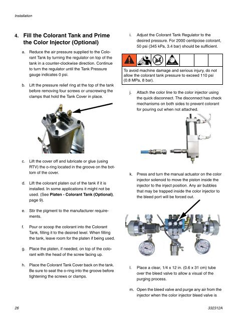
Installation4. Fill the Colorant Tank and Primethe Color Injector (Optional)a. Reduce the air pressure supplied to the ColorantTank by turning the regulator on top of thetank in a counter-clockwise direction. Continueto turn the regulator until the Tank Pressuregauge indicates 0 psi.b. Lift the pressure relief ring at the top of the tankbefore removing four screws or unscrewing theclamps that hold the Tank Cover in place.i. Adjust the Colorant Tank Regulator to thedesired pressure. For 2000 centipoise colorant,50 psi (345 kPa, 3.4 bar) should be sufficient.To avoid machine damage and serious injury, do notallow the colorant tank pressure to exceed 110 psi(0.8 MPa, 8 bar).j. Attach the color line to the color injector usingthe quick disconnect. The disconnect has checkmechanisms on both sides to prevent colorantfor pouring out when not attached.c. Lift the cover off and lubricate or glue (usingRTV) the o-ring located in the groove on the bottomof the cover.d. Lift the colorant platen out of the tank if it isinstalled. In some applications it might not beused. (See Platen - Colorant Tank (Optional),page 9).k. Press and turn the manual actuator on the colorinjector solenoid to move the piston inside theinjector to the inject position. Any air bubblesthat may be trapped inside the color injector tothe bleed port will be forced out.e. Stir the pigment to the manufacturer requirements.f. Pour or scoop the colorant into the ColorantTank, filling it to the desired level. When fillingthe tank, leave room for the platen if being used.g. Place the platen, if needed, on top of the colorantwith the head of the screw facing up.h. Place the Colorant Tank Cover back on the tank.Be sure to seat the o-ring into the groove beforetightening the screws or clamps.l. Place a clear, 1/4 x 12 in. (0.6 x 31 cm) tubeover the bleed valve to allow a visual of thepurging process.m. Open the bleed valve and purge any air from theinjector when the color injector bleed valve is26 <strong>332312A</strong>


