
You also want an ePaper? Increase the reach of your titles
YUMPU automatically turns print PDFs into web optimized ePapers that Google loves.
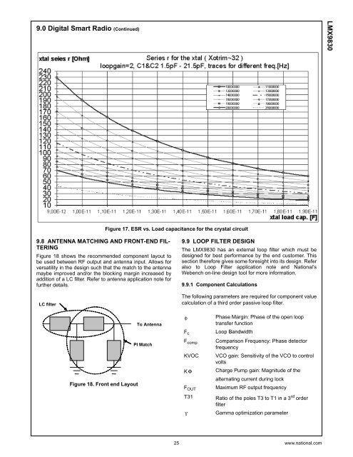
9.0 Digital Smart Radio (Continued)<strong>LMX9830</strong>Figure 17. ESR vs. Load capacitance for the crystal circuit9.8 ANTENNA MATCHING AND FRONT-END FIL-TERINGFigure 18 shows the recommended component layout tobe used between RF output and antenna input. Allows forversatility in the design such that the match to the antennamaybe improved and/or the blocking margin increased byaddition of a LC filter. Refer to antenna application note forfurther details.LC filter9.9 LOOP FILTER DESIGNThe <strong>LMX9830</strong> has an external loop filter which must bedesigned for best performance by the end customer. Thissection therefore gives some foresight into its design. Referalso to Loop Filter application note and National’sWebench on-line design tool for more information.9.9.1 Component CalculationsThe following parameters are required for component valuecalculation of a third order passive loop filter.Figure 18. Front end LayoutTo AntennaPI MatchφF cF compKVOCKΦF OUTT31ϒPhase Margin: Phase of the open looptransfer functionLoop BandwidthComparison Frequency: Phase detectorfrequencyVCO gain: Sensitivity of the VCO to controlvoltsCharge Pump gain: Magnitude of thealternating current during lockMaximum RF output frequencyRatio of the poles T3 to T1 in a 3 rd orderfilterGamma optimization parameter25 www.national.com