C-13872 Instruction E44 Owner's Manual.pdf - Enviro
C-13872 Instruction E44 Owner's Manual.pdf - Enviro
C-13872 Instruction E44 Owner's Manual.pdf - Enviro

You also want an ePaper? Increase the reach of your titles
YUMPU automatically turns print PDFs into web optimized ePapers that Google loves.
Venting fiRepLace inseRts:<br />
Initial Installation<br />
QUALIFIED INSTALLERS ONLY<br />
The ENVIRO <strong>E44</strong> may be installed and vented into any solid fuel fireplace that has been installed in<br />
accordance with the National, Provincial/State and local building codes and has been constructed of noncombustible<br />
materials. Before starting, refer to InItIal InstallatIon - preparIng your e44 For InstallatIon.<br />
Please reference the information in Table 4 and Figures 25, and 27.<br />
An approved chimney liner and rain cap must be used. A throat connector or flashing must be installed to<br />
ensure a tight seal, top performance, safety and efficiency. Carefully follow the manufacturer’s instructions<br />
that accompany the chimney liner kit. Use double walled aluminum flex vent (3” flex conversion piece and<br />
4”x 6 5/8” cap) from any of the following approved products; Simpson Dura-Vent (Direct Vent GS) or (ICC<br />
Excel Direct). If necessary, remove the vent collar plate from the top of the insert and connect it securely<br />
to the liner with sheet metal screws.<br />
Check for any tears in the liner at this point. IMPORTANT: The screws that hold the vent collar plate in its<br />
approved position must be installed.<br />
NOTE: If the <strong>E44</strong> unit is pulled out of its installation, and the vent-air intake system is disconnected<br />
for any reason, ensure that the vent-air intake pipes are re-sealed with high-temperature sealant and<br />
reconnected with three (3) sheet metal screws evenly spaced.<br />
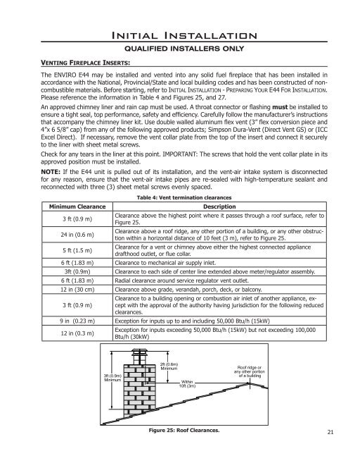
Table 4: Vent termination clearances<br />
Minimum Clearance Description<br />
3 ft (0.9 m)<br />
Clearance above the highest point where it passes through a roof surface, refer to<br />
Figure 25.<br />
24 in (0.6 m)<br />
Clearance above a roof ridge, any other portion of a building, or any other obstruction<br />
within a horizontal distance of 10 feet (3 m), refer to Figure 25.<br />
5 ft (1.5 m)<br />
Clearance for a vent or chimney above either the highest connected appliance<br />
drafthood outlet, or flue collar.<br />
6 ft (1.83 m) Clearance to mechanical air supply inlet.<br />
3ft (0.9m) Clearance to each side of center line extended above meter/regulator assembly.<br />
6 ft (1.83 m) Radial clearance around service regulator vent outlet.<br />
12 in (30 cm) Clearance above grade, verandah, porch, deck, or balcony.<br />
Clearance to a building opening or combustion air inlet of another appliance, ex-<br />
3 ft (0.9 m) cept with the approval of the authority having jurisdiction for the following reduced<br />
clearances.<br />
9 in (0.23 m) Exception for inputs up to and including 50,000 Btu/h (15kW)<br />
12 in (0.3 m)<br />
Exception for inputs exceeding 50,000 Btu/h (15kW) but not exceeding 100,000<br />
Btu/h (30kW)<br />
3ft (0.9m)<br />
Minimum<br />
2ft (0.6m)<br />
Minimum<br />
Within<br />
10ft (3m)<br />
Figure 25: Roof Clearances.<br />
Roof ridge or<br />
any other portion<br />
of a building<br />
21