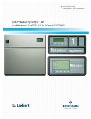
Liebert PPC Precision Power Center
Liebert® PPC™ Precision Power Center - DCES
Liebert® PPC™ Precision Power Center - DCES
- No tags were found...
You also want an ePaper? Increase the reach of your titles
YUMPU automatically turns print PDFs into web optimized ePapers that Google loves.
Operating Instructions3.2 <strong>Power</strong> Monitor PanelMonitored Parameters - A 4-20 character LCD display is provided to indicate the input voltages(line-to-line), output voltages (line-to-line and line-to-neutral), output currents (each phase, neutraland ground), output voltage THD, output current THD, crest factor, K-factor, output kVA, kW,kW-Hours, power factor, percent load and output frequency. Press the Scan button to activate theAutoscan mode where all monitored parameters are sequentially displayed automatically. Momentarilypress the Hold/Sequence button to interrupt the Autoscan mode. Press the Hold/Sequencebutton to allow manual selection of the sequentially displayed stage of overtemperature sensing.After correction of the alarm condition, the alarm will automatically reset.Alarms - When any of the following alarms occurs, an alarm message appears on the LCD, the audiblealarm is activated and the Alarm Present/Silence button is illuminated. Press the Alarm Present/Silencebutton to silence the audible alarm. After the alarm condition is corrected, press theAlarm Present/Silence button to reset the alarm when prompted by a message on the LCD or byany central monitoring system.• Output Overvoltage - Indicates one or more of the output phase voltages has exceeded the presetlimit (normally +6% of nominal). The high output voltage should be verified and correctiveaction taken. In the absence of other procedures, a normal (orderly) system shutdown should beperformed to prevent load equipment damage.• Output Undervoltage - Indicates one or more of the output phase voltages has exceeded thepreset limit (normally 13% of nominal). The low output voltage should be verified and correctiveaction taken. In the absence of other procedures, a normal (orderly) system shutdown should beperformed to prevent load equipment damage.• Output Voltage THD - Indicates that the voltage distortion on one or more of the output phaseshas exceeded the preset limit (normally 10% THD). The cause of the high output voltage distortionshould be investigated and corrective action (if any) taken.• Transformer Overtemp - Indicates a unit transformer overtemperature condition. The cause ofthe overtemperature condition should be investigated and corrected. Possible causes are unitoverload, excessive non-linear loading, inadequate ventilation, high or low input voltage and amonitoring malfunction. Failure to correct the overtemperature condition may result in an automaticsystem shutdown due to the second stage of overtemperature sensing.• Output Overcurrent - Indicates one or more of the output phase currents has exceeded the presetlimit (normally 95% of the unit’s full load amp rating). The overcurrent condition should beverified and corrective action taken. In the absence of other procedures, some of the output loadsshould be turned off to reduce unit loading. If unbalanced phase currents exist, some of the loadsshould be shifted from higher loaded phases to lower loaded phases.• Neutral Overcurrent - Indicates that the neutral current has exceeded the preset limit (normally95% of the unit’s full load amp rating). The overcurrent condition should be verified andinvestigated to see if corrective action is required. In some cases, high neutral current indicatesphase current unbalance which should be corrected. Where high neutral currents are the result ofharmonic load currents, all affected components (including output wiring) should be verified to besuitable for the current.22


