Liebert PPC Precision Power Center
Liebert® PPC™ Precision Power Center - DCES
Liebert® PPC™ Precision Power Center - DCES
- No tags were found...
You also want an ePaper? Increase the reach of your titles
YUMPU automatically turns print PDFs into web optimized ePapers that Google loves.
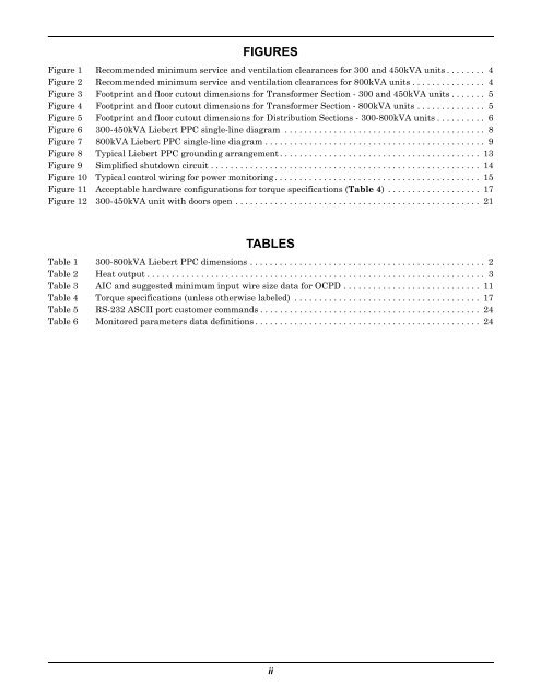
FIGURESFigure 1 Recommended minimum service and ventilation clearances for 300 and 450kVA units . . . . . . . . 4Figure 2 Recommended minimum service and ventilation clearances for 800kVA units . . . . . . . . . . . . . . . 4Figure 3 Footprint and floor cutout dimensions for Transformer Section - 300 and 450kVA units . . . . . . . 5Figure 4 Footprint and floor cutout dimensions for Transformer Section - 800kVA units . . . . . . . . . . . . . . 5Figure 5 Footprint and floor cutout dimensions for Distribution Sections - 300-800kVA units . . . . . . . . . . 6Figure 6 300-450kVA <strong>Liebert</strong> <strong>PPC</strong> single-line diagram . . . . . . . . . . . . . . . . . . . . . . . . . . . . . . . . . . . . . . . . . 8Figure 7 800kVA <strong>Liebert</strong> <strong>PPC</strong> single-line diagram . . . . . . . . . . . . . . . . . . . . . . . . . . . . . . . . . . . . . . . . . . . . . 9Figure 8 Typical <strong>Liebert</strong> <strong>PPC</strong> grounding arrangement . . . . . . . . . . . . . . . . . . . . . . . . . . . . . . . . . . . . . . . . . 13Figure 9 Simplified shutdown circuit . . . . . . . . . . . . . . . . . . . . . . . . . . . . . . . . . . . . . . . . . . . . . . . . . . . . . . . 14Figure 10 Typical control wiring for power monitoring . . . . . . . . . . . . . . . . . . . . . . . . . . . . . . . . . . . . . . . . . . 15Figure 11 Acceptable hardware configurations for torque specifications (Table 4) . . . . . . . . . . . . . . . . . . . 17Figure 12 300-450kVA unit with doors open . . . . . . . . . . . . . . . . . . . . . . . . . . . . . . . . . . . . . . . . . . . . . . . . . . 21TABLESTable 1 300-800kVA <strong>Liebert</strong> <strong>PPC</strong> dimensions . . . . . . . . . . . . . . . . . . . . . . . . . . . . . . . . . . . . . . . . . . . . . . . . 2Table 2 Heat output . . . . . . . . . . . . . . . . . . . . . . . . . . . . . . . . . . . . . . . . . . . . . . . . . . . . . . . . . . . . . . . . . . . . . 3Table 3 AIC and suggested minimum input wire size data for OCPD . . . . . . . . . . . . . . . . . . . . . . . . . . . . 11Table 4 Torque specifications (unless otherwise labeled) . . . . . . . . . . . . . . . . . . . . . . . . . . . . . . . . . . . . . . 17Table 5 RS-232 ASCII port customer commands . . . . . . . . . . . . . . . . . . . . . . . . . . . . . . . . . . . . . . . . . . . . . 24Table 6 Monitored parameters data definitions . . . . . . . . . . . . . . . . . . . . . . . . . . . . . . . . . . . . . . . . . . . . . . 24ii


