Marvell ARMADA 16x Applications Processor Family
7 Marvell ® ARMADA 16x Applications Processor Family ...
7 Marvell ® ARMADA 16x Applications Processor Family ...
- No tags were found...

Create successful ePaper yourself
Turn your PDF publications into a flip-book with our unique Google optimized e-Paper software.
<strong>Marvell</strong> ® <strong>ARMADA</strong> <strong>16x</strong> <strong>Applications</strong> <strong>Processor</strong> <strong>Family</strong><br />
Version 3.2.x Boot ROM Reference Manual<br />
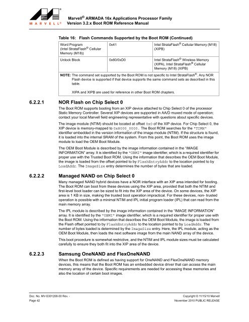
Table 16:<br />
6.2.2.1 NOR Flash on Chip Select 0<br />
Flash Commands Supported by the Boot ROM (Continued)<br />
Word Program<br />
(Intel StrataFlash ® Cellular<br />
Memory (M18))<br />
0x41<br />
The Boot ROM supports booting from an XIP device attached to Chip Select 0 of the processor<br />
Static Memory Controller. Several XIP devices are supported in AA/D muxed mode of operation;<br />
contact your local <strong>Marvell</strong> field engineering representative with questions about specific devices.<br />
The image module (NTIM) should be located at offset 0x0 of the XIP device. For Chip Select 0, the<br />
XIP device is memory-mapped to 0x8000_0000. The Boot ROM searches for the "TIMH"<br />
identifier embedded in the version information of the image module (NTIM). If the structure is found,<br />
it is loaded into the internal SRAM of the system. From this point, the Boot ROM uses the image<br />
module to load the OEM Boot Module.<br />
The OEM Boot Module is described by the image information contained in the “IMAGE<br />
INFORMATION” array. It is identified by the "OBMI" image identifier, which is a required identifier for<br />
proper use with the Trusted Boot ROM. Using the information that describes the OEM Boot Module,<br />
the image is loaded from the offset pointed to by FlashEntryAddr to the location pointed to by<br />
LoadAddr. The ImageSize entry determines the number of bytes that are loaded.<br />
6.2.2.2 Managed NAND on Chip Select 0<br />
Many managed NAND hybrid devices have a NOR interface with an XIP area intended for booting.<br />
The Boot ROM can boot from these devices using the XIP area, provided that both the NTIM and<br />
first-level boot loader can be sized to fit into the XIP area of the device. On some devices, the XIP<br />
area is 1 KB in size, making the trusted boot operation impractical. For these devices, non- trusted<br />
operation is possible with a minimal NTIM and IPL initial program loader (IPL) that can read from the<br />
main memory array.<br />
The IPL module is described by the image information contained in the “IMAGE INFORMATION”<br />
array. It is identified by the "OBMI" image identifier, which is a required identifier for proper use with<br />
the Boot ROM. Using the information that describes the OEM Boot Module, the image is loaded from<br />
the Flash offset pointed to by FlashEntryAddr to the location pointed to by LoadAddr. The<br />
number of bytes loaded is determined by the ImageSize entry. Here, the IPL module, acting as the<br />
OEM Boot Module, then loads the next software image from the main NAND array of the device.<br />
This boot procedure is somewhat restrictive, and the NTIM and IPL module sizes must be calculated<br />
carefully to ensure they both fit into the XIP area of the device.<br />
6.2.2.3 Samsung OneNAND and FlexOneNAND<br />
Intel StrataFlash ® Cellular Memory (M18)<br />
(XIPB)<br />
Unlock Block 0x60/0xD0 Intel StrataFlash ® Wireless Memory<br />
(XIPA), Intel StrataFlash ® Cellular<br />
Memory (M18) (XIPB)<br />
NOTE: The command set supported by the Boot ROM is not specific to Intel StrataFlash ® . Any NOR<br />
Flash device is supported if that device supports the same command sets as described in this<br />
table.<br />
XIPA and XIPB are used for reference in other Boot ROM chapters.<br />
When the Boot ROM is defined as having support for OneNAND and FlexOneNAND memory<br />
devices, this means that the Boot ROM has an embedded device driver that can access the main<br />
memory array of the device. Specific requirements are needed for accessing these memories and<br />
also the location of certain boot images.<br />
1<br />
2<br />
3<br />
4<br />
5<br />
6<br />
7<br />
8<br />
9<br />
10<br />
11<br />
12<br />
13<br />
14<br />
15<br />
16<br />
17<br />
18<br />
19<br />
20<br />
21<br />
22<br />
23<br />
24<br />
25<br />
26<br />
27<br />
28<br />
29<br />
30<br />
31<br />
32<br />
33<br />
34<br />
35<br />
36<br />
37<br />
38<br />
39<br />
40<br />
41<br />
42<br />
43<br />
44<br />
45<br />
46<br />
47<br />
48<br />
49<br />
50<br />
51<br />
52<br />
53<br />
54<br />
55<br />
56<br />
57<br />
58<br />
Doc. No. MV-S301208-00 Rev. - Copyright © 11/15/10 <strong>Marvell</strong><br />
Page 42<br />
November 2010 PUBLIC RELEASE