Marvell ARMADA 16x Applications Processor Family
7 Marvell ® ARMADA 16x Applications Processor Family ...
7 Marvell ® ARMADA 16x Applications Processor Family ...
- No tags were found...

Create successful ePaper yourself
Turn your PDF publications into a flip-book with our unique Google optimized e-Paper software.
<strong>Marvell</strong> ® <strong>ARMADA</strong> <strong>16x</strong> <strong>Applications</strong> <strong>Processor</strong> <strong>Family</strong><br />
Version 3.2.x Boot ROM Reference Manual<br />
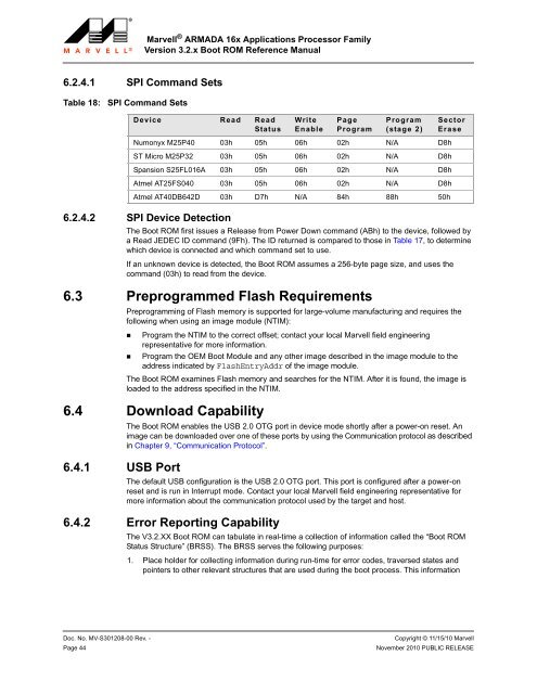
6.2.4.1 SPI Command Sets<br />
Table 18:<br />
SPI Command Sets<br />
6.2.4.2 SPI Device Detection<br />
The Boot ROM first issues a Release from Power Down command (ABh) to the device, followed by<br />
a Read JEDEC ID command (9Fh). The ID returned is compared to those in Table 17, to determine<br />
which device is connected and which command set to use.<br />
If an unknown device is detected, the Boot ROM assumes a 256-byte page size, and uses the<br />
command (03h) to read from the device.<br />
6.3 Preprogrammed Flash Requirements<br />
Preprogramming of Flash memory is supported for large-volume manufacturing and requires the<br />
following when using an image module (NTIM):<br />
• Program the NTIM to the correct offset; contact your local <strong>Marvell</strong> field engineering<br />
representative for more information.<br />
• Program the OEM Boot Module and any other image described in the image module to the<br />
address indicated by FlashEntryAddr of the image module.<br />
The Boot ROM examines Flash memory and searches for the NTIM. After it is found, the image is<br />
loaded to the address specified in the NTIM.<br />
6.4 Download Capability<br />
6.4.1 USB Port<br />
Device Read Read<br />
Status<br />
The Boot ROM enables the USB 2.0 OTG port in device mode shortly after a power-on reset. An<br />
image can be downloaded over one of these ports by using the Communication protocol as described<br />
in Chapter 9, “Communication Protocol”.<br />
The default USB configuration is the USB 2.0 OTG port. This port is configured after a power-on<br />
reset and is run in Interrupt mode. Contact your local <strong>Marvell</strong> field engineering representative for<br />
more information about the communication protocol used by the target and host.<br />
6.4.2 Error Reporting Capability<br />
Write<br />
Enable<br />
Page<br />
Program<br />
Program<br />
(stage 2)<br />
Sector<br />
Erase<br />
Numonyx M25P40 03h 05h 06h 02h N/A D8h<br />
ST Micro M25P32 03h 05h 06h 02h N/A D8h<br />
Spansion S25FL016A 03h 05h 06h 02h N/A D8h<br />
Atmel AT25FS040 03h 05h 06h 02h N/A D8h<br />
Atmel AT40DB642D 03h D7h N/A 84h 88h 50h<br />
The V3.2.XX Boot ROM can tabulate in real-time a collection of information called the “Boot ROM<br />
Status Structure” (BRSS). The BRSS serves the following purposes:<br />
1. Place holder for collecting information during run-time for error codes, traversed states and<br />
pointers to other relevant structures that are used during the boot process. This information<br />
1<br />
2<br />
3<br />
4<br />
5<br />
6<br />
7<br />
8<br />
9<br />
10<br />
11<br />
12<br />
13<br />
14<br />
15<br />
16<br />
17<br />
18<br />
19<br />
20<br />
21<br />
22<br />
23<br />
24<br />
25<br />
26<br />
27<br />
28<br />
29<br />
30<br />
31<br />
32<br />
33<br />
34<br />
35<br />
36<br />
37<br />
38<br />
39<br />
40<br />
41<br />
42<br />
43<br />
44<br />
45<br />
46<br />
47<br />
48<br />
49<br />
50<br />
51<br />
52<br />
53<br />
54<br />
55<br />
56<br />
57<br />
58<br />
Doc. No. MV-S301208-00 Rev. - Copyright © 11/15/10 <strong>Marvell</strong><br />
Page 44<br />
November 2010 PUBLIC RELEASE