INSTALLATION & SERVICING MANUAL BENSON PV TUBULAR CABINET HEATER
Benson PV Range OandM 3366161 Nov2011 issue14 - AmbiRad
Benson PV Range OandM 3366161 Nov2011 issue14 - AmbiRad
- No tags were found...

Create successful ePaper yourself
Turn your PDF publications into a flip-book with our unique Google optimized e-Paper software.
installed without the positive connection of<br />
combustion ductwork within a heated space<br />
and where that heated space has a design<br />
air change of less than 0.5 air changes per<br />
hour and that the installer prefers to<br />
mechanically ventilate the heated space<br />
rather than provide ventilation openings then<br />
The heated space needs to be<br />
mechanically ventilated so that the<br />
design air change is 0.5 air changes<br />
per hour or greater.<br />
<br />
<br />
<br />
It is a requirement that the mechanical<br />
ventilation shall be of the !input! Type<br />
with either natural or mechanical<br />
extraction.<br />
Systems of mechanical extraction with<br />
a natural inlet shall not be used.<br />
It is necessary to provide an automatic<br />
means to safely inhibit heater(s)<br />
operation should mechanical air<br />
supply fail for any reason<br />
2.3.2 Heaters Installed within a Plant<br />
Room or Enclosure.<br />
A plant room means a room housing the<br />
heater plant and probably other items of<br />
building service plant and would generally<br />
have generous space for maintenance.<br />
An enclosure is where the heater is installed<br />
within a compartment or confined area<br />
where space is limited.<br />
Where heaters are installed within a plant<br />
room or enclosure then provision for both<br />
combustion air and / or air for general<br />
ventilation will be required by means of high<br />
and low level ventilation openings (sections<br />
2.3.2.1 and 2.3.2.2 refer to plant room<br />
applications and sections 2.3.2.3 and<br />
2.3.2.4 refer to enclosure applications).<br />
Alternatively the plant room or enclosure<br />
may be mechanically ventilated (section<br />
2.3.2.5 refers)<br />
2.3.2.1 Natural Ventilation Openings<br />
to Plant Rooms for Room Sealed<br />
Heaters<br />
For plant room applications the minimum<br />
free area of ventilation opening will depend<br />
upon whether the heater(s) is installed in<br />
room sealed mode (ie with a positive<br />
connection to atmosphere of both flue and<br />
combustion air).<br />
Or with flue only (ie without the positive<br />
connection to atmosphere of a combustion<br />
air duct)<br />
Where the heater(s) is installed in a plant<br />
room and in room sealed mode (ie with a<br />
positive connection to atmosphere of both<br />
flue and combustion air ) the minimum free<br />
area of ventilation opening needs to be<br />
At high level 5 cm 2 for each kW of<br />
rated heat input.<br />
<br />
At low level 5 cm 2 for each kW of rated<br />
heat input<br />
The high level ventilation opening should be<br />
sited on an external wall and positioned as<br />
high as is practical and always within the top<br />
15% of the wall height.<br />
The low level natural ventilation opening<br />
should be situated on an external wall and<br />
be within 1000 mm of floor level for natural<br />
gas and ideally at floor level for l.p.g gas<br />
installations but in any event no higher than<br />
250 mm.<br />
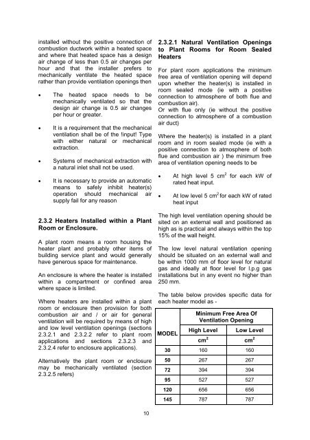
The table below provides specific data for<br />
each heater model as -<br />
MODEL<br />
Minimum Free Area Of<br />
Ventilation Opening<br />
High Level<br />
Low Level<br />
cm 2 cm 2<br />
30 160 160<br />
50 267 267<br />
72 394 394<br />
95 527 527<br />
120 656 656<br />
145 787 787<br />
10