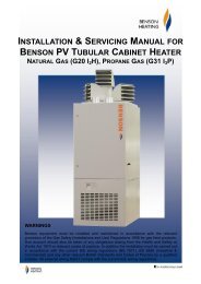
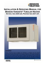
INSTALLATION & SERVICING MANUAL BENSON PV TUBULAR CABINET HEATER
Benson PV Range OandM 3366161 Nov2011 issue14 - AmbiRad
Benson PV Range OandM 3366161 Nov2011 issue14 - AmbiRad
- No tags were found...
You also want an ePaper? Increase the reach of your titles
YUMPU automatically turns print PDFs into web optimized ePapers that Google loves.
2.3.2.2 Natural Ventilation Openings<br />
to Plant Rooms for Flued Heaters<br />
Where the heater(s) is installed in a plant<br />
room and in flue mode (ie without a positive<br />
connection to atmosphere of combustion air<br />
ductwork ) the minimum free area of<br />
ventilation opening needs to be<br />
At high level 2 cm 2 for each kW of<br />
rated heat input.<br />
<br />
At low level 4 cm 2 for each kW of rated<br />
heat input.<br />
The high level ventilation opening should be<br />
sited on an external wall and positioned as<br />
high as is practical and always within the top<br />
15% of the wall height<br />
The low level natural ventilation opening<br />
should be situated on an external wall and<br />
be within 1000 mm of floor level for natural<br />
gas and ideally at floor level for l.p.g gas<br />
installations but in any event no higher than<br />
250 mm.<br />
The table below provides specific data for<br />
each heater model as -<br />
MODEL<br />
Minimum Free Area Of<br />
Ventilation Opening<br />
High Level<br />
Low Level<br />
cm 2 cm 2<br />
30 64 128<br />
50 107 214<br />
72 158 316<br />
95 211 422<br />
120 263 525<br />
145 315 630<br />
2.3.2.3 Natural Ventilation Openings<br />
to Enclosures for Room Sealed<br />
Heaters<br />
For enclosure applications the minimum free<br />
area of ventilation opening will also depend<br />
upon whether the heater(s) is installed in<br />
room sealed mode (ie with a positive<br />
connection to atmosphere of both flue and<br />
combustion air).<br />
11<br />
Or with flue only (ie without the positive<br />
connection to atmosphere of a combustion<br />
air duct)<br />
Where the heater(s) is installed in a plant<br />
room and in room sealed mode (ie with a<br />
positive connection to atmosphere of both<br />
flue and combustion air ) the minimum free<br />
area of ventilation opening needs to be.<br />
At high level 5 cm 2 for each kW of<br />
rated heat input.<br />
<br />
At low level 5 cm 2 for each kW of rated<br />
heat input.<br />
The high level ventilation opening should be<br />
sited on an external wall and positioned as<br />
high as is practical and always within the top<br />
15% of the wall height.<br />
The low level natural ventilation opening<br />
should be situated on an external wall and<br />
be within 1000 mm of floor level for natural<br />
gas and ideally at floor level for l.p.g gas<br />
installations but in any event no higher than<br />
250 mm.<br />
The table below provides specific data for<br />
each heater model as -<br />
MODEL<br />
Minimum Free Area Of<br />
Ventilation Opening<br />
High Level<br />
Low Level<br />
cm 2 cm 2<br />
30 160 160<br />
50 267 267<br />
72 394 394<br />
95 527 527<br />
120 656 656<br />
145 787 787<br />
2.3.2.4 Natural Ventilation Openings<br />
to Enclosures for Flued Heaters<br />
Where the heater(s) is in an enclosure and<br />
in flue only mode (ie without a positive<br />
connection to atmosphere of combustion air<br />
ductwork ) the minimum free area of<br />
ventilation opening needs to be:


