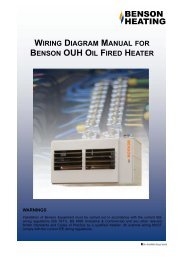
INSTALLATION & SERVICING MANUAL BENSON PV TUBULAR CABINET HEATER
Benson PV Range OandM 3366161 Nov2011 issue14 - AmbiRad
Benson PV Range OandM 3366161 Nov2011 issue14 - AmbiRad
- No tags were found...

You also want an ePaper? Increase the reach of your titles
YUMPU automatically turns print PDFs into web optimized ePapers that Google loves.
4.0 Servicing<br />
Warning<br />
It is a requirement that only qualified<br />
personnel are allowed to carry out<br />
installation commissioning or servicing.<br />
In addition only spare parts recommended<br />
by the manufacturer may be fitted, and the<br />
installer should provide a list of<br />
recommended spare parts that are available<br />
through the manufacturer or his agent (see<br />
section 8).<br />
Before commencing any maintenance or<br />
servicing work the heater must be shut<br />
down and allowed to cool, and have the gas<br />
and electric supplies to it turned off at the<br />
supply cock and isolator respectively.<br />
Always test for gas soundness after<br />
completing any service work particularly<br />
if this has necessitated the removal and /<br />
or replacement of gas carrying<br />
components.<br />
It is advisable that routine inspections are<br />
carried out on a frequent basis, servicing<br />
must also be carried out regularly, and in<br />
accordance with the manufacturers<br />
recommendations i.e. at a maximum interval<br />
of one year. In certain applications the<br />
frequency of servicing will have to be<br />
increased, this to a large extent is governed<br />
by the working environment, and both the<br />
manufacturer and the installer will be able to<br />
offer further advice.<br />
Clean all accessible surfaces including the<br />
outside of the tubular heat exchanger by<br />
removal of the rear panel.<br />
Check for panel damage and that all<br />
fasteners are present and secure.<br />
Visually check all electrical wiring for signs<br />
of damage, possibly through contact with<br />
hot surfaces, check conduit for signs of<br />
chaffing and for security . Check all<br />
terminals are secure and free from<br />
escaped / stray conductor strands.<br />
4.1 Servicing procedure - major<br />
component parts<br />
Heat exchanger<br />
Remove rear panel and carry out visual<br />
inspection of the tubular heat exchanger<br />
using an inspection lamp and mirror.<br />
Check seams and joints for perforations.<br />
Check for severe corrosion and splits in the<br />
heat exchanger.<br />
Check that there are no blockages and that<br />
there is not an excessive build up of soot<br />
within the heat exchanger tubes.<br />
If required remove the burner manifold<br />
allowing access for cleaning, with a flexible<br />
flue brush and vacuum cleaner.<br />
Warning If the heat exchanger is found to<br />
be perforated the heater must not be fired<br />
until a replacement heat exchanger has<br />
been fitted<br />
Injectors and Manifold<br />
Undo the gas pipe connection.<br />
Remove the manifold fixing screws.<br />
Remove the manifold and injector assembly<br />
from the right hand side of the heater.<br />
Check that the manifold is straight, the<br />
injectors are correctly aligned, and that they<br />
are clean, and that there are no<br />
contaminates restricting the orifices, if<br />
necessary clean carefully with compressed<br />
air and or lint free cloth and acetone.<br />
Caution<br />
The injector orifice is precision machined to<br />
fine tolerances, do not clean with hard sharp<br />
or abrasive instruments. If the injectors have<br />
been removed from the manifold, when they<br />
are replaced, and care should be taken not<br />
to over tighten.<br />
Ensure all joints are gas tight.<br />
Fan and Limit Thermostats<br />
Open the front door, so as to gain access.<br />
Remove securing screw from cover, remove<br />
23