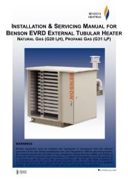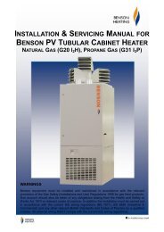
INSTALLATION & SERVICING MANUAL BENSON PV TUBULAR CABINET HEATER
Benson PV Range OandM 3366161 Nov2011 issue14 - AmbiRad
Benson PV Range OandM 3366161 Nov2011 issue14 - AmbiRad
- No tags were found...

Create successful ePaper yourself
Turn your PDF publications into a flip-book with our unique Google optimized e-Paper software.
Failure to do so may invalidate or reduce<br />
guarantee cover.<br />
Plant Room Siting<br />
Provided certain criteria are met it is<br />
possible to install <strong>PV</strong> heaters within a plant<br />
room heaters installed in plant rooms should<br />
only be configured for use in room sealed<br />
mode and provision should be made for the<br />
positive connection of flues , combustion air<br />
pipes, warm air discharge and return<br />
ductwork where such a siting is a<br />
requirement it is recommended that you<br />
consult Benson Technical prior to<br />
installation.<br />
Additionally the maximum temperature<br />
within the plant room should not exceed<br />
32 0 C<br />
etc) it is considered favourable if the heater<br />
is positioned so as the discharge towards or<br />
across the cold air source from a distance<br />
from 1.5m - 6m dependent upon the size of<br />
the entrance and the air throw<br />
characteristics of the heater. On exposed<br />
walls heaters should be positioned so as to<br />
discharge towards, or along the length of the<br />
exposed wall.<br />
In areas where it is proposed that more than<br />
one heater is to be installed, a general<br />
scheme of circulation should be drawn up<br />
and maintained, thereby offering the best<br />
heat distribution. Air pressure within the<br />
area heated and the outside air pressure<br />
must remain the same, factors influencing<br />
this would be the presence of extraction<br />
systems, ventilation systems, and various<br />
types of process plant.<br />
2.0 Installation<br />
The location chosen for the heater must<br />
allow for the fitting of an effective flue<br />
system.<br />
The location must also allow for adequate<br />
clearance for the air supply, return air<br />
circulation, gas supply, electrical supply,<br />
whilst also providing good and safe working<br />
access.<br />
The heater must be installed on a flat and<br />
level surface made from non-combustible<br />
material, which is sufficiently robust to<br />
withstand the weight of the heater and any<br />
ancillary equipment.<br />
Any combustible material adjacent to the<br />
heater or flue system must be so placed or<br />
shielded so that its surface temperature<br />
does not exceed 65 0 C.<br />
<strong>PV</strong> free blowing heaters are at their most<br />
effective when located as close to the<br />
working area as possible. However care<br />
should be exercised to avoid directing the<br />
discharged air directly onto the occupants of<br />
the area to be heated.<br />
Where the passage of cold air causes<br />
problems (e.g. by entrances, loading bays<br />
2.1 Installation Clearances<br />
The Heater must be installed within the<br />
clearances indicated below in mm’s<br />
Model Front Rear Lhs Rhs<br />
30/50 700 400 150 150<br />
72/95 840 400 150 150<br />
120/145 840 400 150 150<br />
2.2 Warm Air Circulation<br />
The air heater should be positioned to<br />
enable maximum circulation of discharged<br />
warm air within the area to be heated, whilst<br />
taking account of personnel within the area,<br />
sources of cold air ingress, and<br />
obstructions.<br />
The air temperature rise on passing the heat<br />
exchanger is typically around 33 0 C<br />
A full and unobstructed return air path to the<br />
air heater must be provided<br />
(see 2.4 Air Supply).<br />
Where the heater is positioned to deliver<br />
blown air through an opening in a wall,<br />
return air intakes should be located so that<br />
8