
Create successful ePaper yourself
Turn your PDF publications into a flip-book with our unique Google optimized e-Paper software.
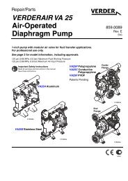
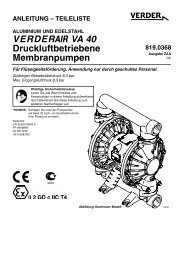
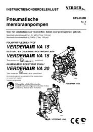
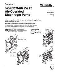
INSTRUCTIONS–PARTS LIST<br />
<strong>VERDER</strong> <strong>VA</strong> <strong>10</strong><br />
<strong>Air</strong>-<strong>Operated</strong><br />
<strong>Diaphragm</strong> <strong>Pumps</strong><br />
819.0154<br />
Rev. Z<br />
<br />
For fluid transfer applications. For professional use only.<br />
Only pumps with acetal fluid sections are approved for use in European<br />
explosive atmosphere locations.<br />
7 bar Maximum Fluid Working Pressure<br />
7 bar Maximum <strong>Air</strong> Input Pressure<br />
INSTRUCTIONS<br />
This manual contains important<br />
warnings and information.<br />
READ AND RETAIN FOR REFERENCE<br />
*NOTE: Refer to the Pump Listing on page 20 to find Model No. of your pump.<br />
*<br />
1428<br />
* Only applies to pumps with Acetal fluid sections.
Table of Contents<br />
Safety Warnings . . . . . . . . . . . . . . . . . . . . . . . . . . . . . . . . . . . . . 2<br />
Installation . . . . . . . . . . . . . . . . . . . . . . . . . . . . . . . . . . . . . . . . . . 4<br />
Operation . . . . . . . . . . . . . . . . . . . . . . . . . . . . . . . . . . . . . . . . . <strong>10</strong><br />
Maintenance . . . . . . . . . . . . . . . . . . . . . . . . . . . . . . . . . . . . . . . 11<br />
Troubleshooting . . . . . . . . . . . . . . . . . . . . . . . . . . . . . . . . . . . . 12<br />
Service<br />
Replacing the <strong>Air</strong> Valve . . . . . . . . . . . . . . . . . . . . . . . . . . . 13<br />
Repairing the <strong>Air</strong> Valve . . . . . . . . . . . . . . . . . . . . . . . . . . . 15<br />
Ball Check Valves . . . . . . . . . . . . . . . . . . . . . . . . . . . . . . . 17<br />
<strong>Diaphragm</strong> Repair . . . . . . . . . . . . . . . . . . . . . . . . . . . . . . . 18<br />
Pump Listing . . . . . . . . . . . . . . . . . . . . . . . . . . . . . . . . . . . . . . . 20<br />
Repair Kit Listing . . . . . . . . . . . . . . . . . . . . . . . . . . . . . . . . . . . 21<br />
Parts . . . . . . . . . . . . . . . . . . . . . . . . . . . . . . . . . . . . . . . . . . . . . 22<br />
Torque Sequence . . . . . . . . . . . . . . . . . . . . . . . . . . . . . . . . . . . 25<br />
Dimensions . . . . . . . . . . . . . . . . . . . . . . . . . . . . . . . . . . . . . . . . 26<br />
Mounting Hole Layouts . . . . . . . . . . . . . . . . . . . . . . . . . . . . . . 26<br />
Technical Data and Performance Charts . . . . . . . . . . . . . . . 27<br />
Customer Services/Guarantee . . . . . . . . . . . . . . . . . . . . . . . . 29<br />
Symbols<br />
Warning Symbol<br />
Warning<br />
This symbol alerts you to the possibility of serious injury or<br />
death if you do not follow the instructions.<br />
Caution Symbol<br />
Caution<br />
This symbol alerts you to the possibility of damage to or destruction<br />
of equipment if you do not follow the instructions.<br />
Warning<br />
EQUIPMENT MISUSE HAZARD<br />
INSTRUCTIONS<br />
Equipment misuse can cause the equipment to rupture or malfunction and result in serious injury.<br />
<br />
This equipment is for professional use only.<br />
<br />
<br />
<br />
<br />
<br />
<br />
<br />
<br />
<br />
<br />
Read all instruction manuals, tags, and labels before operating the equipment.<br />
Use the equipment only for its intended purpose. If you are not sure, call <strong>VERDER</strong> After Sales Service.<br />
Do not alter or modify this equipment.<br />
Check equipment daily. Repair or replace worn or damaged parts immediately.<br />
Do not exceed the maximum working pressure of the lowest rated component in your system. This equipment<br />
has a 7 bar maximum working pressure at 7 bar maximum incoming air pressure.<br />
Use fluids and solvents which are compatible with the equipment wetted parts. Refer to the Technical Data<br />
section of all equipment manuals. Read the fluid and solvent manufacturer’s warnings.<br />
Do not use hoses to pull equipment.<br />
Route hoses away from traffic areas, sharp edges, moving parts, and hot surfaces. Do not expose <strong>VERDER</strong><br />
hoses to temperatures above 82C or below -40C.<br />
Do not lift pressurized equipment.<br />
Comply with all applicable local, state, and national fire, electrical, and safety regulations.<br />
2 819.0154
Warning<br />
TOXIC FLUID HAZARD<br />
Hazardous fluid or toxic fumes can cause serious injury or death if splashed in the eyes or on the skin, inhaled,<br />
or swallowed.<br />
<br />
<br />
<br />
<br />
<br />
Know the specific hazards of the fluid you are using.<br />
Store hazardous fluid in an approved container. Dispose of hazardous fluid according to all local, state and<br />
national guidelines.<br />
Always wear protective eyewear, gloves, clothing and respirator as recommended by the fluid and solvent<br />
manufacturer.<br />
Pipe and dispose of the exhaust air safely, away from people, animals, and food handling areas. If the<br />
diaphragm fails, the fluid is exhausted along with the air. See <strong>Air</strong> Exhaust Ventilation on page 9.<br />
To pump acids, always use a polypropylene pump. Take precautions to avoid acid or acid fumes from<br />
contacting the pump housing exterior. Stainless steel parts can be damaged by exposure to acid spills and<br />
fumes. Never use an acetal pump to pump acids.<br />
FIRE AND EXPLOSION HAZARD<br />
Improper grounding, poor ventilation, open flames or sparks can cause a hazardous condition and result in a fire<br />
or explosion and serious injury.<br />
Ground the equipment. Refer to Grounding on page 5.<br />
<br />
<br />
<br />
<br />
<br />
<br />
<br />
<br />
<br />
<br />
Never us a polypropylene pump with non-conductive flammable fluids as specified by your local fire protection<br />
code. Refer to Grounding on page 5 for additional information. Consult your fluid supplier to determine<br />
the conductivity or resistivity of your fluid.<br />
If there is any static sparking or you feel an electric shock while using this equipment, stop pumping immediately.<br />
Do not use the equipment until you identify and correct the problem.<br />
Provide fresh air ventilation to avoid the buildup of flammable fumes from solvents or the fluid being pumped.<br />
Pipe and dispose of the exhaust air safely, away from all sources of ignition. If the diaphragm fails, the fluid is<br />
exhausted along with the air. See <strong>Air</strong> Exhaust Ventilation on page 9.<br />
Keep the work area free of debris, including solvent, rags, and gasoline.<br />
Electrically disconnect all equipment in the work area.<br />
Extinguish all open flames or pilot lights in the work area.<br />
Do not smoke in the work area.<br />
Do not turn on or off any light switch in the work area while operating or if fumes are present.<br />
Do not operate a gasoline engine in the work area.<br />
819.0154 3
Installation<br />
General Information<br />
1. The Typical Installations in Figs. 2–3 are only guides for<br />
selecting and installing system components. Contact<br />
your <strong>VERDER</strong> Customer Service for assistance in planning<br />
a system to suit your needs.<br />
2. Always use Genuine <strong>VERDER</strong> Parts and Accessories.<br />
Refer to the Product Data Sheets. If you supply your own<br />
accessories, be sure they are adequately sized and<br />
pressure rated for your system.<br />
3. Use a compatible, liquid thread sealant or PTFE tape on<br />
all male threads. Tighten all connections firmly to avoid<br />
air or fluid leaks. Do not overtighten plastic threads.<br />
4. Reference numbers and letters in parentheses refer to<br />
the callouts in the Figures and the parts lists on pages<br />
22 to 24.<br />
Tightening Screws Before First Use<br />
Before using the pump for the first time, check and retorque<br />
all external fasteners. See Torque Sequence, page 25. After<br />
the first day of operation, retorque the fasteners. Although<br />
pump use varies, a general guideline is to retorque fasteners<br />
every two months.<br />
Warning<br />
TOXIC FLUID HAZARD<br />
Hazardous fluid or toxic fumes can cause<br />
serious injury or death if splashed in the eyes<br />
or on the skin, inhaled, or swallowed.<br />
1. Read TOXIC FLUID HAZARD on page 3.<br />
2. Use fluids and solvents which are compatible with the<br />
equipment wetted parts. Refer to the Technical Data<br />
section of all equipment manuals. Read the fluid and<br />
solvent manufacturer’s Warnings.<br />
Safe Operating Temperature<br />
Minimum: 4.4C; Maximum: 66C.<br />
Operating outside these temperature limits will adversely<br />
affect the strength of the pump housing. Certain chemicals<br />
may further reduce the operating temperature range. Consult<br />
engineering guides for chemical compatibilities and<br />
temperature limits, or contact <strong>VERDER</strong> After Sales Service.<br />
Mountings<br />
Caution<br />
1. Be sure the mounting can support the weight of the<br />
pump, hoses, and accessories, as well as the stress<br />
caused during operation.<br />
2. The <strong>VERDER</strong>AIR <strong>VA</strong> <strong>10</strong> Pump can be used in a variety<br />
of installations, some of which are shown in Figs. 4–3.<br />
Kits are available to adapt your pump to your system.<br />
Refer to the Product Data Sheets.<br />
3. For all other mountings, be sure the pump is adequately<br />
secured.<br />
Dual Manifolds<br />
Dual manifold kits are available to enable you to pump two<br />
fluids simultaneously, or to mix two fluids in the pump. Order<br />
Part No. 819.0155 for acetal pumps and Part No. 819.0156<br />
for polypropylene pumps.<br />
4 819.0154
Installation<br />
Grounding<br />
Warning<br />
FIRE AND EXPLOSION HAZARD<br />
This pump must be grounded. Before operating<br />
the pump, ground the system as explained<br />
at right. Also read the section FIRE<br />
AND EXPLOSION HAZARD on page 3.<br />
The acetal pump contains stainless steel<br />
fibers that make the wetted parts conductive.<br />
Attaching the ground wire to the<br />
grounding strip grounds the air motor and the wetted<br />
parts. The polypropylene pump is not conductive.<br />
When pumping conductive flammable fluids, always<br />
ground the fluid system by making sure the fluid has an<br />
electrical path to a true earth ground. See Fig. 2 and 3.<br />
Never use a polypropylene pump with non-conductive<br />
flammable fluids as specified by your local fire protection<br />
code. U.S. Code (NFPA 77 Static Electricity) recommends<br />
a conductivity greater than 50 x <strong>10</strong> –12 Siemans/meter<br />
(mhos/meter) over your operating temperature range to<br />
reduce the hazard of fire. Consult your fluid supplier to<br />
determine the conductivity or resistivity of your fluid. The<br />
resistivity must be less than 2 x <strong>10</strong> 12 ohm-centimeters.<br />
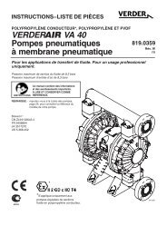
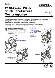
Ground all of this equipment:<br />
<br />
Pump: Attach a ground wire (Y) to the grounding<br />
strip (112) with the screw (28), lockwashers (29) and<br />
nut (27), as shown in Fig. 1. Connect the clamp end of the<br />
ground wire to a true earth ground. Order Part<br />
No. 819.0157 Ground Wire and Clamp.<br />
NOTE: When pumping conductive flammable fluids with a<br />
polypropylene or a PVDF pump, always ground the entire<br />
fluid system. See the WARNING left.<br />
Fig. 1<br />
<br />
<br />
27<br />
29<br />
112<br />
28<br />
<strong>Air</strong> and fluid hoses: Use only electrically conductive<br />
hoses.<br />
Y<br />
01432B<br />
<strong>Air</strong> compressor: Follow the manufacturer’s recommendations.<br />
To reduce the risk of static sparking, ground the pump and all<br />
other equipment used or located in the pumping area. Check<br />
your local electrical code for detailed grounding instructions<br />
for your area and type of equipment.<br />
<br />
<br />
Solvent pails used when flushing: Follow your local code.<br />
Use only metal pails, which are conductive. Do not place<br />
the pail on a non-conductive surface, such as paper or<br />
cardboard, which interrupts the grounding continuity.<br />
Fluid supply container: Follow your local code.<br />
819.0154 5
Installation<br />
<strong>Air</strong> Line<br />
Warning<br />
A bleed-type master air valve (B) is required in your system<br />
to relieve air trapped between this valve and the pump. See<br />
Figs. 2–3. Trapped air can cause the pump to cycle unexpectedly,<br />
which could result in serious injury, including<br />
splashing in the eyes or on the skin, injury from moving<br />
parts, or contamination from hazardous fluids.<br />
Caution<br />
The pump exhaust air may contain contaminants. Ventilate<br />
to a remote area if the contaminants could affect your fluid<br />
supply. See <strong>Air</strong> Exhaust Ventilation on page 9.<br />
1. Install the air line accessories as shown in Figs. 2–3.<br />
Mount these accessories on the wall or on a bracket. Be<br />
sure the air line supplying the accessories is grounded.<br />
a. The fluid pressure can be controlled. To control it on<br />
the air side, install an air regulator (H).<br />
b. Locate one bleed-type master air valve (B) close to<br />
the pump and use it to relieve trapped air. See the<br />
Warning above. Locate the other master air<br />
valve (E) upstream from all air line accessories and<br />
use it to isolate them during cleaning and repair.<br />
c. The air line filter (F) removes harmful dirt and moisture<br />
from the compressed air supply.<br />
2. Install an electrically conductive, flexible air hose (C)<br />
between the accessories and the 1/4 npt(f) pump air inlet<br />
(see Fig. 4). Use a minimum 6.3 mm ID air hose. Screw<br />
an air line quick disconnect coupler (D) onto the end of<br />
the air hose (C), and screw the mating fitting into the<br />
pump air inlet snugly. Do not connect the coupler (D) to<br />
the fitting yet.<br />
Fluid Suction Line<br />
1. If using a conductive (Acetal) pump, use conductive<br />
hoses. If using a non-conductive pump, ground the fluid<br />
system. See Grounding on page 5. The pump fluid<br />
inlet is 3/8 bspt. See Fig. 4. Screw the fluid fitting into the<br />
pump inlet snugly.<br />
2. At inlet fluid pressures greater than 1.05 bar, diaphragm<br />
life will be shortened.<br />
3. See the Technical Data on pages 27 and 28 for maximum<br />
suction lift and flow rate loss at various lift distances.<br />
Fluid Outlet Line<br />
Warning<br />
A fluid drain valve (J) is required in your system to relieve<br />
pressure in the hose if it is plugged. See Figs. 2–3. The<br />
drain valve reduces the risk of serious injury, including<br />
splashing in the eyes or on the skin, or contamination from<br />
hazardous fluids when relieving pressure. Install the valve<br />
close to the pump fluid outlet.<br />
1. Use electrically conductive fluid hoses (N). Depending<br />
on your model, the pump fluid outlet is 3/8 bspt or 3/8<br />
npt(f). See Fig. 4. Screw the fluid fitting into the pump<br />
outlet snugly.<br />
2. Install a fluid drain valve (J) near the fluid outlet. See the<br />
Warning above.<br />
6 819.0154
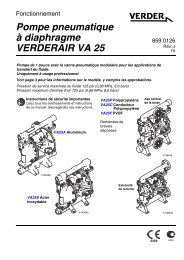
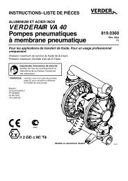
Installation<br />
BUNG-MOUNT TRANSFER INSTALLATION<br />
WALL-MOUNT TRANSFER INSTALLATION<br />
KEY<br />
KEY<br />
A<br />
B<br />
C<br />
D<br />
E<br />
F<br />
H<br />
J<br />
L<br />
M<br />
N<br />
Y<br />
<strong>VERDER</strong>AIR <strong>VA</strong> <strong>10</strong> Pump<br />
Bleed-Type Master <strong>Air</strong> Valve<br />
(required for pump)<br />
<strong>Air</strong> Supply Line<br />
<strong>Air</strong> Line Quick Disconnect<br />
Master <strong>Air</strong> Valve (for accessories)<br />
<strong>Air</strong> Line Filter<br />
Pump <strong>Air</strong> Regulator<br />
Fluid Drain Valve (required)<br />
Fluid Suction Line<br />
Fluid Inlet Filter<br />
Fluid Supply Hose<br />
Ground Wire (required; see page5<br />
for installation instructions)<br />
A <strong>VERDER</strong>AIR <strong>VA</strong> <strong>10</strong> Pump<br />
B Bleed-Type Master <strong>Air</strong> Valve<br />
(required for pump)<br />
C <strong>Air</strong> Supply Line<br />
D <strong>Air</strong> Line Quick Disconnect<br />
E Master <strong>Air</strong> Valve (for accessories)<br />
F <strong>Air</strong> Line Filter<br />
H Pump <strong>Air</strong> Regulator<br />
J Fluid Drain Valve (required)<br />
L Fluid Suction Line<br />
N Fluid Supply Hose<br />
S Wall Bracket<br />
T Bung Adapter<br />
Y Ground Wire (required; see page 5<br />
for installation instructions)<br />
E<br />
F H B<br />
C<br />
E<br />
F H B<br />
C<br />
N<br />
M<br />
A<br />
D<br />
N<br />
J<br />
A<br />
D<br />
J<br />
Y<br />
T<br />
Y<br />
S<br />
L<br />
L<br />
01444<br />
Fig. 2<br />
01457<br />
Fig. 3<br />
819.0154 7
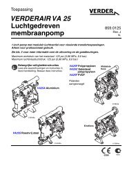
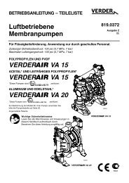
Installation<br />
Changing the Orientation of the Fluid Inlet and<br />
Outlet Ports<br />
The pump is shipped with the fluid inlet and outlet ports facing<br />
the same direction. See Fig. 4. If desired, the direction of<br />
one or both ports can be changed. Remove the manifold(s)<br />
from the pump as explained in steps 1–2 and 4 on page 17.<br />
Reattach with the port facing the desired direction. See<br />
Torque Sequence, page 25. Do not over-torque.<br />
Acetal Pump Shown<br />
1<br />
Apply thread lube and torque to 5.6–6.8 Nm. Do not<br />
over-torque. See Torque Sequence, page 25.<br />
2 1/4 npt(f) <strong>Air</strong> Inlet<br />
Fluid Pressure Relief Valve<br />
Caution<br />
Some systems may require installation of a pressure relief<br />
valve at the pump outlet to prevent overpressurization and<br />
rupture of the pump or hose. See Fig. 5.<br />
Thermal expansion of fluid in the outlet line can cause overpressurization.<br />
This can occur when using long fluid lines<br />
exposed to sunlight or ambient heat, or when pumping from<br />
a cool to a warm area (for example, from an underground<br />
tank).<br />
Overpressurization can also occur if the <strong>VERDER</strong>AIR pump<br />
is being used to feed fluid to a piston pump, and the intake<br />
valve of the piston pump does not close, causing fluid to<br />
back up in the outlet line.<br />
3 3/8 bspt or 3/8 npt(f) Fluid Inlet Port<br />
4 3/8 bspt or 3/8 npt(f) Fluid Outlet Port<br />
5 3/8 npt(f) <strong>Air</strong> Exhaust Port<br />
2<br />
1<br />
4<br />
KEY<br />
A 3/8 bspt or 3/8 npt(f) Fluid Inlet Port<br />
B 3/8 bspt or 3/8 npt(f) Fluid Outlet Port<br />
C Pressure Relief Valve<br />
Part No. 819.0159 (Stainless Steel)<br />
1<br />
Install valve between fluid inlet and outlet ports.<br />
2 Connect fluid inlet line here.<br />
3<br />
Connect fluid outlet line here.<br />
B 3<br />
C 1<br />
3<br />
1<br />
5<br />
01459<br />
Fig. 4<br />
Fig. 5<br />
A<br />
2<br />
01539<br />
8 819.0154
Installation<br />
<strong>Air</strong> Exhaust Ventilation<br />
Warning<br />
FIRE AND EXPLOSION HAZARD<br />
Be sure to read FIRE OR EXPLOSION<br />
HAZARD and TOXIC FLUID HAZARD on<br />
page 3, before operating this pump.<br />
Be sure the system is properly ventilated for<br />
your type of installation. You must vent the<br />
exhaust to a safe place, away from people,<br />
animals, food handling areas, and all sources<br />
of ignition when pumping flammable or hazardous<br />
fluids.<br />
<strong>Diaphragm</strong> failure will cause the fluid being<br />
pumped to exhaust with the air. Place an appropriate container<br />
at the end of the air exhaust line to catch the fluid.<br />
See Fig. 6.<br />
The air exhaust port is 3/8 npt(f). Do not restrict the air exhaust<br />
port. Excessive exhaust restriction can cause erratic<br />
pump operation.<br />
To exhaust to a remote location:<br />
1. Remove the muffler (11) from the pump air exhaust port.<br />
Warning<br />
PRESSURIZED EQUIPMENT HAZARD<br />
To reduce the risk of serious eye injury<br />
from ice particles, never operate the pump<br />
with the air exhaust port open. Ice may<br />
form during pump operation, and ice particles<br />
will be ejected from the port along with the exhaust<br />
air. If the muffler (11) is removed, always connect an air<br />
exhaust hose to the exhaust port.<br />
2. Install an electrically conductive air exhaust hose (X) and<br />
connect the muffler to the other end of the hose. The<br />
minimum size for the air exhaust hose is <strong>10</strong> mm ID. If a<br />
hose longer than 4.57 m is required, use a larger diameter<br />
hose. Avoid sharp bends or kinks in the hose.<br />
3. Place a container (Z) at the end of the air exhaust line to<br />
catch fluid in case a diaphragm ruptures. If the fluid is<br />
flammable, ground the container. See Fig. 6.<br />
VENTING EXHAUST AIR (Submerged Installation Shown)<br />
In a submerged installation (as shown), all wetted and non-wetted pump parts must be<br />
compatible with the fluid being pumped.<br />
Z<br />
11<br />
Fig. 6<br />
X<br />
01445A<br />
819.0154 9
Operation<br />
Pressure Relief Procedure<br />
PRESSURIZED EQUIPMENT HAZARD<br />
The system pressure must be manually relieved to prevent<br />
the system from starting or spraying accidentally. To reduce<br />
the risk of an injury from accidental spray from the gun,<br />
splashing fluid, or moving parts, follow the Pressure Relief<br />
Procedure whenever you:<br />
are instructed to relieve the pressure,<br />
stop spraying,<br />
check or service any of the system equipment,<br />
or install or clean the spray tips.<br />
1. Shut off the air to the pump.<br />
Warning<br />
2. Open the dispensing valve, if used.<br />
3. Open the fluid drain valve to relieve all fluid pressure,<br />
having a container ready to catch the drainage.<br />
Flush the Pump Before First Use<br />
The pump was tested with lightweight oil, which is left<br />
in the fluid passages to protect parts. To avoid contaminating<br />
your fluid with oil, flush the pump with a compatible<br />
solvent before using the equipment. Follow the<br />
steps under Starting and Adjusting the Pump.<br />
Starting and Adjusting the Pump<br />
Warning<br />
TOXIC FLUID HAZARD<br />
Hazardous fluid or toxic fumes can cause<br />
serious injury or death if splashed in the eyes<br />
or on the skin, inhaled, or swallowed. Do not<br />
lift a pump under pressure. If dropped, the<br />
fluid section may rupture. Always follow the Pressure Relief<br />
Procedure above before lifting the pump.<br />
1. Be sure the pump is properly grounded. Read FIRE OR<br />
EXPLOSION HAZARD on page 3.<br />
2. Check all fittings to be sure they are tight. Be sure to use<br />
a compatible liquid thread sealant or PTFE tape on all<br />
male threads. Tighten the fluid inlet and outlet fittings<br />
snugly. Do not overtighten the fittings into the pump.<br />
3. Place the suction tube (if used) in the fluid to be pumped.<br />
4. Place the end of the fluid hose (N) into an appropriate<br />
container. Close the fluid drain valve (J).<br />
5. With the pump air regulator (H) closed, open all bleedtype<br />
master air valves (B, E).<br />
6. If the fluid hose has a dispensing device, hold it open<br />
while continuing with the following step. Slowly open the<br />
air regulator (H) until the pump starts to cycle. Allow the<br />
pump to cycle slowly until all air is pushed out of the lines<br />
and the pump is primed.<br />
If you are flushing, run the pump long enough to thoroughly<br />
clean the pump and hoses. Close the air regulator.<br />
Remove the suction tube from the flushing fluid and<br />
place it in the fluid to be pumped.<br />
Pump Shutdown<br />
Warning<br />
To reduce the risk of serious injury whenever you are<br />
instructed to relieve pressure, always follow the Pressure<br />
Relief Procedure at left.<br />
At the end of the work shift, relieve the pressure.<br />
<strong>10</strong> 819.0154
Maintenance<br />
Lubrication<br />
The air valve is designed to operate unlubricated, however if<br />
lubrication is desired, every 500 hours of operation (or monthly)<br />
remove the hose from the pump air inlet and add two<br />
drops of machine oil to the air inlet.<br />
Caution<br />
Do not over-lubricate the pump. Oil is exhausted through<br />
the muffler, which could contaminate your fluid supply or<br />
other equipment. Excessive lubrication can also cause the<br />
pump to malfunction.<br />
Flushing and Storage<br />
Warning<br />
To reduce the risk of serious injury whenever you are<br />
instructed to relieve pressure, always follow the Pressure<br />
Relief Procedure on page <strong>10</strong>.<br />
Tightening the Clamps<br />
When tightening the clamps (111), apply thread lubricant to<br />
the bolts and be sure to torque the nuts (113) to 5.6–6.8<br />
Nm. See Fig. 7. See Torque Sequence, page 25.<br />
1<br />
Apply thread lube and torque nuts to 5.6–6.8 Nm.<br />
See Torque Sequence, page 25.<br />
111<br />
Flush the pump when necessary to prevent the fluid you are<br />
pumping from drying or freezing in the pump and damaging it.<br />
Use a compatible fluid.<br />
Before storing the pump, always flush the pump and relieve<br />
the pressure.<br />
Tightening Threaded Connections<br />
Before each use, check all hoses for wear or damage, and<br />
replace as necessary. Check to be sure all threaded connections<br />
are tight and leak free.<br />
Fig. 7<br />
Preventive Maintenance Schedule<br />
113<br />
1<br />
01446<br />
Check fasteners. Tighten or retorque as necessary. Although<br />
pump use varies, a general guideline is to retorque<br />
fasteners every two months. See Torque Sequence, page<br />
25.<br />
Establish a preventive maintenance schedule, based on the<br />
pump’s service history. This is especially important for prevention<br />
of spills or leakage due to diaphragm failure.<br />
819.0154 11
Troubleshooting<br />
Warning<br />
To reduce the risk of serious injury whenever you are<br />
instructed to relieve pressure, always follow the Pressure<br />
Relief Procedure on page <strong>10</strong>.<br />
1. Relieve the pressure before checking or servicing the<br />
equipment.<br />
2. Check all possible problems and causes before disassembling<br />
the pump.<br />
PROBLEM CAUSE SOLUTION<br />
The pump will not cycle, or cycles<br />
once and stops.<br />
The pump cycles at stall or fails to<br />
hold pressure at stall.<br />
There is excessive air leakage from<br />
the exhaust port.<br />
The air valve is stuck or dirty. Turn the reset shaft (21).<br />
Disassemble and clean the air valve.<br />
See pages 15, 16.<br />
Use filtered air.<br />
The detent link (22) is worn or broken. Replace the detent link (22) and ball (8).<br />
See pages 15, 16.<br />
The springs (3, 6) and/or valve cup (5) and<br />
plate (13) are broken or damaged.<br />
Replace these parts. See pages 15, 16.<br />
The check valves or o-rings (<strong>10</strong>8) are leaking. Replace these parts. See page 17.<br />
The check balls (301) or seat (201) are worn. Replace these parts. See page 17.<br />
The check ball (301) is wedged in the seat<br />
(201).<br />
Replace the ball. See page 17.<br />
The air valve cup (5) or plate (13) is worn. Replace these parts. See pages 15, 16.<br />
The shaft seals (30) are worn. Replace the seals. See page 18.<br />
The pump operates erratically. The suction line is clogged. Inspect; clear the line.<br />
The check valve balls (301) are sticking or<br />
leaking.<br />
Clean or replace the balls. See page 17.<br />
The diaphragm (401) is ruptured. Replace the diaphragm. See page 18.<br />
There are air bubbles in the fluid. The suction line is loose. Tighten the suction line.<br />
The diaphragm (401) is ruptured. Replace the diaphragm. See page 18.<br />
The manifolds (<strong>10</strong>2) are loose or the<br />
o-rings (<strong>10</strong>8) are damaged.<br />
Tighten the manifold bolts (<strong>10</strong>4) or<br />
nuts (<strong>10</strong>6); replace the o-rings (<strong>10</strong>8).<br />
See page 17.<br />
The outer diaphragm plates (<strong>10</strong>3) are loose. Tighten the plates. See page 18.<br />
There is fluid in the exhaust air. The diaphragm (401*) is ruptured. Replace the diaphragm. See page 18.<br />
The outer diaphragm plates (<strong>10</strong>3) are loose. Tighten the plates. See page 18.<br />
The pump exhausts air at stall. The air valve cup (5) or plate (13) is worn. Replace these parts. See pages 15, 16.<br />
The pump exhausts air from the<br />
clamps.<br />
The pump exhausts air near the air<br />
valve.<br />
The pump leaks fluid from the check<br />
valves.<br />
The shaft seals (31) are worn. Replace the seals. See page 18.<br />
The clamps (111) are loose. Tighten the clamp nuts (113).<br />
See page 11.<br />
The air valve screws (15) are loose. Tighten the screws. See page 13.<br />
The air valve o-ring (19) is damaged.<br />
The o-rings (<strong>10</strong>8) are worn or damaged.<br />
Inspect; replace the o-ring. See<br />
pages 15, 16.<br />
Inspect; replace the o-rings. See page<br />
17.<br />
12 819.0154
Service<br />
Tools Required<br />
<br />
<br />
<br />
Torque wrench<br />
Phillips screwdriver<br />
O-ring pick<br />
Replacing the <strong>Air</strong> Valve<br />
NOTE: <strong>Air</strong> Valve Kit 819.6864 is available. Parts included in<br />
the kit are marked with a dagger, for example (2).<br />
A tube of general purpose grease (26) is supplied in<br />
the kit. Install the kit as follows.<br />
Warning<br />
To reduce the risk of serious injury whenever you are<br />
instructed to relieve pressure, always follow the Pressure<br />
Relief Procedure on page <strong>10</strong>.<br />
1. Relieve the pressure.<br />
2. Unscrew the six mounting screws (15) and remove the<br />
air valve (A) from the pump. See Fig. 8.<br />
3. Refer to the Valve Plate Detail in Fig. 8. Remove the two<br />
screws (<strong>10</strong>) holding the valve plate (13) to the pump.<br />
Use an o-ring pick to remove the valve plate, seal (12),<br />
and bearing (9).<br />
4. Apply grease (26) to the bearing (9). Install the bearing<br />
and the seal (12) in the pump housing (1). Install the<br />
valve plate (13) and secure with the two screws (<strong>10</strong>), as<br />
shown. Torque the screws to 0.6–0.8 Nm.<br />
5. Make certain the o-ring (19) is in place on the air valve<br />
cover (2).<br />
6. Apply grease (26) where shown in Fig. 8.<br />
7. Align the new air valve assembly so the reset shaft (21)<br />
is at the top. Install the valve on the pump, making sure<br />
the valve saddle (14) engages the recessed area on<br />
the diaphragm shaft (23). Install the six screws (15) and<br />
torque oppositely and evenly, to 0.9–1.6 Nm.<br />
819.0154 13
Service<br />
<strong>VA</strong>LVE PLATE DETAIL<br />
19<br />
12<br />
21<br />
13<br />
4<br />
A<br />
2<br />
<strong>10</strong><br />
1<br />
9<br />
3<br />
01458<br />
GREASE APPLICATION<br />
1<br />
15<br />
3<br />
14<br />
21<br />
3<br />
01436<br />
4<br />
112<br />
3<br />
19<br />
1<br />
Torque oppositely and evenly to 0.9–1.6 Nm.<br />
2<br />
3<br />
Torque to 0.6–0.8 Nm.<br />
Apply grease (26).<br />
3<br />
2<br />
Fig. 8<br />
03412A<br />
14 819.0154
Service<br />
Tools Required<br />
1. Relieve the pressure.<br />
<br />
Torque wrench<br />
2. Remove the air valve from the pump (see page 13).<br />
<br />
<br />
<br />
Phillips screwdriver<br />
O-ring pick<br />
Rubber mallet<br />
Repairing the <strong>Air</strong> Valve<br />
Disassembly<br />
Warning<br />
To reduce the risk of serious injury whenever you are<br />
instructed to relieve pressure, always follow the Pressure<br />
Relief Procedure on page <strong>10</strong>.<br />
3. Remove the screw (15) and shift saddle (14). See Fig. 9.<br />
4. Disassemble the link assembly, consisting of the actuator<br />
link (16), spacer (17), detent link (22), spring (3),<br />
stop (4), and valve cup (5).<br />
5. Remove the detent ball (8) and spring (6). The detent<br />
collar (7) is a press-fit and should not need removal; if it<br />
does require replacement, you should also replace the<br />
cover (2).<br />
6. Remove the reset shaft (21), o-ring (20) and<br />
washer (18).<br />
7. Clean all parts and inspect for wear or damage. Replace<br />
as needed. See Reassembly, page 16.<br />
NOTE: ALL PARTS SHOWN ARE INCLUDED IN AIR <strong>VA</strong>LVE KIT 819.6864.<br />
20<br />
2<br />
21<br />
18<br />
22<br />
17<br />
16<br />
14<br />
7<br />
15<br />
8<br />
6<br />
19<br />
5<br />
Fig. 9<br />
3<br />
4<br />
01431A<br />
819.0154 15
Service<br />
Reassembly<br />
1. If the detent collar (7) was removed, carefully install a<br />
new collar in a new cover (2), using a rubber mallet.<br />
See Fig. <strong>10</strong>.<br />
2. Grease the spring (6) and place it in the collar (7).<br />
Grease the ball (8) and set it on the spring.<br />
3. Grease the o-ring (20) and install it in the hole (H) in the<br />
cover (2). See Fig. <strong>10</strong>. Slide the washer (18) onto the<br />
blunt end of the reset shaft (21). Insert the shaft through<br />
the cover (2) until it seats.<br />
1 Apply grease (26).<br />
2 Bumps face up.<br />
3 Reset shaft square must engage with square hole.<br />
2<br />
2<br />
5<br />
16<br />
1 17<br />
1 22<br />
4<br />
1<br />
8<br />
4. Grease the spring (3). Place the link stop (4) inside the<br />
spring.<br />
3<br />
1<br />
3<br />
1<br />
2<br />
1<br />
Apply grease (26).<br />
Press fit with rubber mallet.<br />
21<br />
1<br />
8<br />
6<br />
7<br />
1<br />
2<br />
Fig. 11<br />
2<br />
7505A<br />
1<br />
18<br />
20<br />
8. Grease the inside surfaces of the shift saddle (14) and<br />
install it as shown in Fig. 12. Hold the link assembly firmly<br />
in place and install the screw (15). Torque to 0.8 to<br />
1.0 Nm. Install the o-ring (19) on the cover (2).<br />
9. Reinstall the air valve as explained on page 13.<br />
H<br />
1<br />
Apply grease (26).<br />
Fig. <strong>10</strong><br />
2<br />
01437<br />
2<br />
Torque to 0.8 to 1.0 Nm.<br />
1 14<br />
15<br />
2<br />
5. Grease the detent link (22) and link spacer (17). Assemble<br />
the detent link, link spacer, and actuator link (16)<br />
as shown in Fig. 11. The raised bumps on the links (22<br />
and 16) must face up.<br />
1 5<br />
1 22<br />
19<br />
6. Squeeze the spring (3) and install it and the stop (4) in<br />
the link assembly. The spring tension will hold all these<br />
parts together. Grease the valve cup (5) and install it in<br />
the link assembly as shown.<br />
21<br />
1<br />
7. Install the link assembly on the cover (2) so the pointed<br />
end of the reset shaft (21) fits through the holes in the<br />
links and the square part of the shaft engages the<br />
square hole. Make certain the bumps on the detent<br />
link (22) engage the ball (8).<br />
Fig. 12<br />
2<br />
7506A<br />
16 819.0154
Service<br />
Tools Required<br />
<br />
<br />
<br />
Torque wrench<br />
13 mm socket wrench<br />
O-ring pick<br />
Ball Check Valves<br />
NOTE: A Fluid Section Repair Kit is available. See page 21<br />
for the correct kit. Parts included in the kit are marked<br />
with an asterisk, for example (301*). Use all the parts<br />
in the kit for the best results. Always replace the<br />
o-rings (<strong>10</strong>8) with new ones whenever the old ones<br />
are removed.<br />
Warning<br />
<strong>10</strong>. Reassemble the outlet ball checks in the top of the<br />
pump, following all notes in Fig. 13. Be sure the ball<br />
checks are assembled exactly as shown. To avoid<br />
pump leakage, run your finger over the o-rings (<strong>10</strong>8) and<br />
ensure that they are seated properly.<br />
11. Install the top manifold (<strong>10</strong>2) and four nuts (<strong>10</strong>6). Torque<br />
to 5.6–6.8 Nm. Do not over-torque. See Torque Sequence,<br />
page 25.<br />
<strong>10</strong>6<br />
4 5<br />
<strong>10</strong>4<br />
1<br />
<strong>10</strong>2<br />
6<br />
To reduce the risk of serious injury whenever you are<br />
instructed to relieve pressure, always follow the Pressure<br />
Relief Procedure on page <strong>10</strong>.<br />
1. Relieve the pressure. Disconnect all hoses. Remove<br />
the pump from its mounting.<br />
2. Using a 1/2” socket wrench, remove the nuts (<strong>10</strong>6) holding<br />
the top manifold (<strong>10</strong>2) to the covers (<strong>10</strong>1). Lift the<br />
manifold off the pump. See Fig. 13.<br />
3. Remove the outer o-ring (<strong>10</strong>8), ball guide (202),<br />
ball (301), seat (201), and inner o-ring (<strong>10</strong>8) from each of<br />
the covers.<br />
<strong>10</strong>8*<br />
202*<br />
301*<br />
201*<br />
<strong>10</strong>8*<br />
<strong>10</strong>1<br />
3<br />
2<br />
4. Turn the pump over. Pull the tie rods (<strong>10</strong>4) out of the<br />
pump, leaving the four nuts (<strong>10</strong>6) on the rods. Remove<br />
the feet (<strong>10</strong>7) and lower manifold (<strong>10</strong>2).<br />
5. Remove the outer o-ring (<strong>10</strong>8), seat (201), ball (301), ball<br />
guide (202), and inner o-ring (<strong>10</strong>8) from each of the<br />
covers (<strong>10</strong>1).<br />
6. Clean all parts and inspect for wear or damage. Replace<br />
parts as needed.<br />
7. Reassemble the intake ball checks in the bottom of the<br />
pump, following all notes in Fig. 13. Be sure the ball<br />
checks are assembled exactly as shown.<br />
8. Set the lower manifold (<strong>10</strong>2) and feet (<strong>10</strong>7) in place on<br />
the bottom of the pump.<br />
9. Insert the long threads of each rod (<strong>10</strong>4) through the feet<br />
and lower manifold. Push the rods up through the<br />
covers (<strong>10</strong>1) until the nut (<strong>10</strong>6) on the end of the rods<br />
bottoms on the foot. Make sure the rods are pushed all<br />
the way through. Turn the pump upright (the rods are a<br />
slight interference fit and will hold the pump parts securely<br />
in place).<br />
1<br />
2<br />
3<br />
4<br />
5<br />
Fig. 13<br />
Apply thread lubricant.<br />
Flat side faces ball.<br />
Beveled end up.<br />
Torque to 5.6–6.8 Nm. See<br />
Torque Sequence, page 25.<br />
Do not over-torque.<br />
6 Long threads at top.<br />
<strong>10</strong>8*<br />
202* 3<br />
301*<br />
201* 2<br />
<strong>10</strong>8*<br />
<strong>10</strong>2<br />
<strong>10</strong>7<br />
<strong>10</strong>6<br />
4 5<br />
02457B<br />
819.0154 17
Service<br />
Tools Required<br />
<br />
<br />
<br />
<br />
<br />
<br />
<br />
Torque wrench<br />
One 11 mm and two 13 mm<br />
socket wrenches<br />
Phillips screwdriver<br />
O-ring pick<br />
13/32” EZY-OUT bearing extractor<br />
Rubber mallet<br />
Vise with soft jaws<br />
<strong>Diaphragm</strong> Repair<br />
Disassembly<br />
NOTE: A Fluid Section Repair Kit is available. See page 21<br />
for the correct kit. Parts included in the kit are marked<br />
with an asterisk, for example (401*). Use all the parts<br />
in the kit for the best results.<br />
Warning<br />
To reduce the risk of serious injury whenever you are<br />
instructed to relieve pressure, always follow the Pressure<br />
Relief Procedure on page <strong>10</strong>.<br />
1. Relieve the pressure. Disconnect all hoses.<br />
2. Remove the air valve from the pump (see page 13).<br />
3. Remove the manifolds (<strong>10</strong>2) and disassemble the ball<br />
check valves as explained on page 17. Always replace<br />
the o-rings (<strong>10</strong>8) with new ones.<br />
4. Using a 7/16” socket wrench, remove the clamp<br />
nuts (113) and the grounding strip (112). Loosen the<br />
clamps (111) and slip them over the housing (1). Pull the<br />
covers (<strong>10</strong>1) off the pump, then remove the clamps from<br />
the housing. See the Detail in Fig. 14.<br />
5. Using a 1/2” socket wrench on both outer diaphragm<br />
plates (<strong>10</strong>3), unscrew one plate from the diaphragm<br />
shaft (23). Remove one diaphragm (401), inner diaphragm<br />
plate (118), and o-ring (404). Pull the opposite<br />
diaphragm assembly and the diaphragm shaft out of the<br />
pump housing (1). See Fig. 14. Clamp the shaft in a vise<br />
with soft jaws and unscrew the outer plate (<strong>10</strong>3), then<br />
disassemble the remaining diaphragm assembly.<br />
6. Inspect the diaphragm shaft (23) for wear or scratches. If<br />
it is damaged, check the bearings (31) also. Replace<br />
parts as needed. To remove the bearings, place a<br />
13/32 EZY-OUT in a vise. Position the pump housing (1)<br />
over the EZY-OUT (see Fig. 14). Turn the housing in the<br />
direction shown by the arrows to remove the bearing.<br />
7. Hook the shaft seals (30) with an o-ring pick and pull<br />
them out of the housing (1).<br />
8. Clean all parts and inspect for wear or damage. Replace<br />
parts as needed.<br />
Reassembly<br />
1. Install the shaft seals (30) in the housing (1). Using a<br />
rubber mallet, carefully drive the bearings (31) flush into<br />
the housing so the holes face out. See Fig. 14.<br />
2. Grease the diaphragm shaft (23) and slide it into the<br />
housing (1). Install the o-rings (404*) in the grooves of<br />
the housing.<br />
3. Assemble the inner diaphragm plates (118), diaphragms<br />
(401*), and outer diaphragm plates (<strong>10</strong>3) as<br />
shown in Fig. 14. Apply medium-strength (blue) Loctite<br />
or equivalent to the threads of the fluid-side plates (<strong>10</strong>3),<br />
and torque the plates to 8.5 to 9.6 Nm at <strong>10</strong>0 rpm maximum<br />
using a 1/2” socket wrench. Do not over-torque.<br />
These parts must be assembled correctly.<br />
Caution<br />
Do not over-torque the outer diaphragm plates (<strong>10</strong>3). Doing<br />
so will damage the hex heads.<br />
4. When installing the covers (<strong>10</strong>1), slip the clamps (111)<br />
over the housing (1) before positioning the covers. See<br />
the Detail in Fig. 14. Engage the notches in the covers<br />
with the locator tabs on the housing, then position the<br />
clamps over both parts. The clamp bolts should be on<br />
the air valve side of the housing, and pointing down toward<br />
the bottom of the pump. Install the grounding strip<br />
on the bolts. Apply thread lubricant to the bolts, then<br />
install the clamp nuts (113). Using a 7/16” socket<br />
wrench, torque the nuts to 5.6–6.8 Nm. See Torque<br />
Sequence, page 25.<br />
5. Reassemble the ball check valves and manifolds as<br />
explained on page 17. Always install new o-rings (<strong>10</strong>8*),<br />
and make sure they are seated<br />
properly.<br />
6. Reinstall the air valve, using the six mounting<br />
screws (15). See Fig. 8.<br />
18 819.0154
Service<br />
1<br />
2<br />
3<br />
4<br />
6<br />
Grease shaft.<br />
Apply thread lubricant.<br />
Flat side faces ball.<br />
Beveled end up.<br />
Round side must face toward diaphragm.<br />
1<br />
<strong>10</strong>6<br />
8 9<br />
<strong>10</strong>4 2<br />
7<br />
8<br />
9<br />
Apply medium-strength (blue) Loctite or equivalent.<br />
Torque to 8.5–9.6 Nm at <strong>10</strong>0 rpm maximum.<br />
Torque to 5.6–6.8 Nm. See Torque Sequence,<br />
page 25.<br />
Do not over-torque.<br />
<strong>10</strong> Notches must engage tabs.<br />
<strong>10</strong>2<br />
*<strong>10</strong>8<br />
202*<br />
4<br />
301*<br />
201*<br />
3<br />
<strong>10</strong>1<br />
112<br />
*404<br />
<strong>10</strong>1<br />
111<br />
<strong>10</strong><br />
113 8<br />
23<br />
1<br />
118<br />
*401<br />
<strong>10</strong>3<br />
7<br />
2<br />
8<br />
111<br />
113<br />
*<strong>10</strong>8<br />
<strong>10</strong>6<br />
202*<br />
4<br />
301*<br />
1<br />
201* 3<br />
2<br />
01440<br />
DETAIL OF CLAMPS AND COVERS<br />
404*<br />
1<br />
Acetal Model Shown<br />
<strong>10</strong>2<br />
<strong>10</strong>7<br />
<strong>10</strong>6<br />
8 9<br />
30<br />
FLUID SIDE<br />
AIR SIDE<br />
31<br />
01441<br />
1<br />
<strong>10</strong>3<br />
7 9<br />
30<br />
31<br />
*401<br />
Fig. 14<br />
118 6<br />
23 1<br />
CUTAWAY VIEW OF DIAPHRAGM<br />
ASSEMBLIES IN PUMP HOUSING<br />
13/32 IN. EZY-OUT<br />
01443<br />
01442<br />
DETAIL OF BEARING REMO<strong>VA</strong>L USING EZY-OUT<br />
819.0154 19
Pump Listing<br />
<strong>VERDER</strong> <strong>VA</strong> <strong>10</strong> Acetal and Polypropylene <strong>Pumps</strong>, Series F<br />
Your Model No. is marked on the pump’s serial plate. The listing of existing <strong>VERDER</strong>AIR <strong>VA</strong> <strong>10</strong> pumps is below:<br />
Part No.<br />
Inlet/Outlet<br />
Threads<br />
Fluid<br />
Section Seats Balls <strong>Diaphragm</strong>s<br />
8<strong>10</strong>.0001* ACE ACE TEF TEF<br />
8<strong>10</strong>.0004* ACE ACE 316 TEF<br />
8<strong>10</strong>.0012* ACE ACE BUN BUN<br />
8<strong>10</strong>.0013* ACE 316 TEF TEF<br />
8<strong>10</strong>.0016* ACE 316 316 TEF<br />
8<strong>10</strong>.0017* ACE 316 316 HYT<br />
8<strong>10</strong>.0044<br />
8<strong>10</strong>.0049<br />
BSPT<br />
POL ACE HYT HYT<br />
POL 316 TEF TEF<br />
8<strong>10</strong>.0052 POL 316 316 TEF<br />
8<strong>10</strong>.0061 POL POL TEF TEF<br />
8<strong>10</strong>.0068 POL POL HYT HYT<br />
8<strong>10</strong>.0072 POL POL BUN BUN<br />
8<strong>10</strong>.0215** ACE ACE TEF TEF<br />
8<strong>10</strong>.5427 POL POL SAN SAN<br />
8<strong>10</strong>.0465* ACE ACE TEF TEF<br />
8<strong>10</strong>.0466* ACE ACE 316 TEF<br />
8<strong>10</strong>.0467* ACE ACE 316 BUN<br />
8<strong>10</strong>.0468* ACE ACE BUN BUN<br />
8<strong>10</strong>.0469*<br />
8<strong>10</strong>.0470<br />
NPT(f)<br />
ACE 316 TEF TEF<br />
POL 316 TEF TEF<br />
8<strong>10</strong>.0471 POL 316 316 TEF<br />
8<strong>10</strong>.0472 POL POL TEF TEF<br />
8<strong>10</strong>.0473 POL POL HYT HYT<br />
8<strong>10</strong>.0474 POL POL BUN BUN<br />
ACE = Acetal BUN = Buna-N HYT = TPE POL = Polypropylene 316 = 316 sst TEF = PTFE SAN = Santoprene<br />
* certified.<br />
** Reverse manifold.<br />
20 819.0154
Repair Kit Listing<br />
For <strong>VERDER</strong> <strong>VA</strong> <strong>10</strong> Acetal and Polypropylene <strong>Pumps</strong>, Series F<br />
Repair Kits may only be ordered as kits. To repair the air valve, order Part No. 819.6864 (see page 24). Parts included in the <strong>Air</strong><br />
Valve Repair Kit are marked with a symbol in the parts list, for example (2). The list of existing Repair Kits is below:<br />
Part No. O-Rings Seats Balls <strong>Diaphragm</strong>s<br />
819.0061 TEF NUL NUL SAN<br />
819.0074 TEF NUL NUL TEF<br />
819.0075 TEF NUL NUL HYT<br />
819.0076 TEF NUL NUL BUN<br />
819.0097 TEF ACE TEF NUL<br />
819.0098 TEF ACE TEF TEF<br />
819.0<strong>10</strong>2 TEF ACE 316 NUL<br />
819.0<strong>10</strong>5 TEF ACE HYT NUL<br />
819.0<strong>10</strong>7 TEF ACE HYT HYT<br />
819.0<strong>10</strong>9 TEF ACE BUN NUL<br />
819.0112 TEF ACE BUN BUN<br />
819.0118 TEF 316 TEF TEF<br />
819.0117 TEF 316 TEF NUL<br />
819.0121 TEF 316 316 NUL<br />
819.0122 TEF 316 316 TEF<br />
819.0124 TEF 316 316 BUN<br />
819.0137 TEF POL TEF NUL<br />
819.0138 TEF POL TEF TEF<br />
819.0145 TEF POL HYT NUL<br />
819.0147 TEF POL HYT HYT<br />
819.0149 TEF POL BUN NUL<br />
819.0152 TEF POL BUN BUN<br />
819.5442 TEF 316 316 SAN<br />
ACE = Acetal BUN = Buna-N HYT = TPE POL = Polypropylene 316 = 316 sst TEF = PTFE NUL = Null<br />
SAN = Santoprene<br />
819.0154 21
Parts<br />
<strong>10</strong>6<br />
Acetal Model Shown<br />
<strong>10</strong>4<br />
1<br />
11<br />
<strong>10</strong>2<br />
23<br />
<strong>10</strong>9<br />
<strong>10</strong>8*<br />
401*<br />
<strong>10</strong>3<br />
202*<br />
301*<br />
<strong>10</strong><br />
15<br />
12<br />
9<br />
13<br />
30<br />
31<br />
118<br />
*404<br />
201*<br />
<strong>10</strong>8*<br />
<strong>10</strong>1<br />
<br />
27<br />
29<br />
111<br />
<strong>10</strong>6<br />
28<br />
<strong>10</strong>8*<br />
112<br />
202*<br />
113<br />
301*<br />
201*<br />
<strong>10</strong>8*<br />
<strong>10</strong>2<br />
<strong>10</strong>7<br />
<strong>10</strong>6<br />
* Included in Pump Repair Kit, which may only be purchased<br />
as a kit. See page 21.<br />
<br />
Included in <strong>Air</strong> Valve Kit 819.6864, which may only be purchased<br />
as a kit. See parts list on page 24.<br />
01429E<br />
<br />
<br />
Included in <strong>Diaphragm</strong> Shaft Kit 819.6349, which may be<br />
purchased separately.<br />
Not supplied with polypropylene pump..<br />
Replacement Danger and Warning labels, tags and cards<br />
are available at no cost.<br />
22 819.0154
Parts<br />
Fluid Section Parts List<br />
Fluid<br />
section<br />
material<br />
A<br />
C<br />
E<br />
T<br />
A<br />
L<br />
Ref.<br />
No. Part No. Description Qty<br />
<strong>10</strong>1 819.0188 COVER, fluid; acetal<br />
with conductive sst<br />
fibers<br />
<strong>10</strong>2 819.0313 MANIFOLD; acetal<br />
with conductive sst<br />
fibers; BSPT<br />
819.0189 MANIFOLD; acetal<br />
with conductive fibers;<br />
NPT<br />
<strong>10</strong>3 819.0190 PLATE, fluid side;<br />
acetal<br />
<strong>10</strong>4 819.0203 ROD, tie; 5/16–18 4<br />
<strong>10</strong>5 None Not Used 0<br />
<strong>10</strong>6 819.9748 NUT; 5/16–18 8<br />
<strong>10</strong>7 819.0193 FEET 2<br />
<strong>10</strong>8 819.0194 O-RING; PTFE 8<br />
<strong>10</strong>9<br />
<br />
819.6313 LABEL, warning 1<br />
111 819.0196 CLAMP 2<br />
112 819.6354 STRIP, grounding 1<br />
113 819.0198 NUT, clamp; 1/4–28 2<br />
118 819.6356 PLATE, air side; sst 2<br />
P <strong>10</strong>1 819.0200 COVER, fluid; 2<br />
O<br />
polypropylene<br />
L<br />
Y<br />
<strong>10</strong>2 819.0201 MANIFOLD;<br />
P<br />
polypropylene; BSPT<br />
2<br />
R<br />
819.6475 MANIFOLD;<br />
2<br />
O<br />
polypropylene; NPT<br />
P<br />
Y <strong>10</strong>3 819.0202 PLATE, fluid side; 2<br />
L<br />
polypropylene<br />
E<br />
N<br />
<strong>10</strong>4 819.0203 ROD, tie; 5/16–18 4<br />
E <strong>10</strong>5 None Not Used 0<br />
<strong>10</strong>6 819.9748 NUT; 5/16–18 8<br />
<strong>10</strong>7 819.0193 FEET 2<br />
<strong>10</strong>8 819.0194 O-RING; PTFE 8<br />
<strong>10</strong>9<br />
<br />
819.6313 LABEL, warning 1<br />
111 819.0196 CLAMP 2<br />
113 819.0198 NUT, clamp; 1/4–28 2<br />
118 819.6356 PLATE, air side; sst 2<br />
2<br />
2<br />
2<br />
2<br />
Ball Parts List<br />
Ref.<br />
No. Part No. Description Qty<br />
301* 819.02<strong>10</strong> BALL; PTFE 4<br />
301* 819.0211 BALL; 316 stainless steel 4<br />
301* 819.0212 BALL; TPE 4<br />
301* 819.0213 BALL; buna-N 4<br />
Seat Parts List<br />
Seat<br />
material<br />
A<br />
C<br />
E<br />
T<br />
A<br />
L<br />
3<br />
1<br />
6<br />
S<br />
S<br />
T<br />
P<br />
O<br />
L<br />
Y<br />
P<br />
R<br />
O<br />
P<br />
Y<br />
L<br />
E<br />
N<br />
E<br />
Ref.<br />
No. Part No. Description Qty<br />
201* 819.0205 SEAT; acetal 4<br />
202* 819.0206 GUIDE; acetal 4<br />
201* 819.0207 SEAT; 316 stainless<br />
steel<br />
202* 819.0206 GUIDE; acetal 4<br />
201* 819.0208 SEAT; polypropylene 4<br />
202* 819.0209 GUIDE;<br />
polypropylene<br />
<strong>Diaphragm</strong> Parts List<br />
<strong>Diaphragm</strong><br />
material<br />
P<br />
T<br />
F<br />
E<br />
Ref.<br />
No. Part No. Description Qty<br />
401* 819.0214 DIAPHRAGM; PTFE 2<br />
404* 819.0217 O-RING; buna-N 2<br />
T 401* 819.0218 DIAPHRAGM; TPE 2<br />
P<br />
E 404* 819.0217 O-RING; buna-N 2<br />
B<br />
U<br />
N<br />
A<br />
–<br />
N<br />
401* 819.0219 DIAPHRAGM;<br />
buna-N<br />
404* 819.0217 O-RING; buna-N 2<br />
S<br />
401* 819.0060 DIAPHRAGM; 2<br />
A<br />
Santoprene<br />
N 404* 819.0217 O–RING; buna–N 2<br />
4<br />
4<br />
2<br />
819.0154 23
Parts<br />
<strong>Air</strong> Motor Parts List<br />
Ref.<br />
No. Part No. Description Qty<br />
1 819.0161 HOUSING, center;<br />
polypropylene<br />
2 819.0162 COVER, air valve; polypropylene 1<br />
3 819.0163 SPRING, compression; sst 1<br />
4 819.0164 STOP, link; acetal 1<br />
5 819.6863 CUP, valve; acetal 1<br />
6 819.0166 SPRING, compression; sst 1<br />
7 819.0167 COLLAR, detent; sst 1<br />
8 819.0168 BALL, detent; carbide 1<br />
9 819.0169 BEARING, link; acetal 1<br />
<strong>10</strong> 819.0170 SCREW, thread-forming;<br />
1/4–20; 9.5 mm long;<br />
11 819.6351 MUFFLER 1<br />
12 819.0172 SEAL, plate, valve; buna-N; 1<br />
13 819.0173 PLATE, valve; sst 1<br />
14 819.0174 SADDLE, shift; acetal 1<br />
15 819.0175 SCREW, thread-forming;<br />
<strong>10</strong>–14 size; 19 mm long; see<br />
below and page 22<br />
1<br />
2<br />
7<br />
Ref.<br />
No. Part No. Description Qty<br />
<br />
16 819.0176 LINK, actuator; sst 1<br />
17 819.0177 SPACER, link; acetal 1<br />
18 819.0178 WASHER, plain; sst 1<br />
19 819.0179 O-RING; buna-N 1<br />
20 819.0180 O-RING; buna-N 1<br />
21 819.0181 SHAFT, reset; sst 1<br />
22 819.6862 LINK, detent; sst 1<br />
23 819.6353 SHAFT, diaphragm; sst 1<br />
26 819.0184 GREASE, general purpose;<br />
<strong>10</strong>.5 g; not shown<br />
27 819.0185 NUT, hex; <strong>10</strong>–24 1<br />
28 819.6880 SCREW; <strong>10</strong>–24; 8 mm long 1<br />
29 819.0187 LOCKWASHER, int. tooth; no. <strong>10</strong> 1<br />
30 819.6352 PACKING, o-ring; fluoroelastomer<br />
31 819.6350 BEARING, acetal 2<br />
These parts are included in <strong>Air</strong> Valve Kit 819.6864, which<br />
may only be purchased as a kit. The kit includes only one<br />
screw (15), shown below, and a tube of grease (26).<br />
1<br />
2<br />
<br />
These parts are included in <strong>Diaphragm</strong> Shaft Kit<br />
819.6349, which may be purchased separately.<br />
20<br />
2<br />
21<br />
18<br />
17<br />
22<br />
16<br />
14<br />
15<br />
3<br />
4<br />
5<br />
8<br />
6<br />
19<br />
7<br />
01431A<br />
24 819.0154
Torque Sequence<br />
Always follow torque sequence when instructed to torque fasteners.<br />
1. Left/Right Fluid Covers<br />
Torque bolts to 5.6–6.8 Nm.<br />
3. Inlet Manifold<br />
Torque bolts to 5.6–6.8 Nm.<br />
9<br />
7<br />
2<br />
1<br />
8<br />
<strong>10</strong><br />
FRONT VIEW<br />
BOTTOM VIEW<br />
2. Outlet Manifold<br />
Torque bolts to 5.6–6.8 Nm.<br />
5<br />
3<br />
4 6<br />
TOP VIEW<br />
819.0154 25
Dimensions<br />
FRONT VIEW<br />
SIDE VIEW<br />
1/4 npt(f)<br />
<strong>Air</strong> Inlet<br />
3/8 bspt<br />
Fluid Outlet*<br />
157.0 mm<br />
206.5 mm<br />
3/8 npt(f)<br />
<strong>Air</strong> Exhaust<br />
(muffler included)<br />
28.7 mm<br />
3/8 bspt<br />
Fluid Inlet*<br />
26.9 mm<br />
134.6 mm<br />
203.2 mm<br />
01459<br />
01447<br />
* <strong>Pumps</strong> 8<strong>10</strong>.0465–8<strong>10</strong>.0474 have npt(f) threads on the fluid inlet and fluid outlet.<br />
Mounting Hole Layouts<br />
WALL BRACKET 819–5951<br />
<strong>VERDER</strong> <strong>VA</strong> <strong>10</strong> PUMP (TOP VIEW)<br />
228.6 mm<br />
160 mm<br />
88.9 mm<br />
127 mm<br />
(WALL VIEW)<br />
203 mm<br />
171.2 mm<br />
7.14 mm<br />
Diameter (4)<br />
Four 11 mm Dia. Holes<br />
(To Mount Bracket To Wall)<br />
26 819.0154<br />
0654<br />
01448
Technical Data<br />
<strong>Pumps</strong> with PTFE <strong>Diaphragm</strong>s<br />
Maximum Fluid Working Pressure . . . . . . . . . . . . . . . . . . . 7 bar<br />
<strong>Air</strong> Pressure Operating Range . . . . . . . . . . . . . . . . . . 1.4–7 bar<br />
Maximum <strong>Air</strong> Consumption . . . . . . 0.15 N m 3 /min (see chart)<br />
Maximum Free Flow Delivery . . . . . . . . . . . . . . . . . . . 24.6 l/min<br />
Maximum Pump Speed . . . . . . . . . . . . . . . . . . . . . . . . 330 cpm<br />
Maximum Suction Lift . . . . . . . . . . . . . . . 2.1 m dry; 3.7 m wet<br />
Maximum Size Pumpable Solids . . . . . . . . . . . . . . . . . . 1.6 mm<br />
Sound Power Level (at 7 bar, full flow) . . . . . . . . . . . . . 85 dBa<br />
Typical Sound Power Level (at 4.9 bar, 308 l/min) . . . 78 dBa<br />
Operating Temperature Range . . . . . . . . . . . . . . . 4.4–65.5C<br />
<strong>Air</strong> Inlet Size . . . . . . . . . . . . . . . . . . . . . . . . . . . . . . . . . 1/4 npt(f)<br />
Fluid Inlet and Outlet Size. . . . . . . . . . . . . . . . . . . . . . . 3/8 bspt<br />
Models 8<strong>10</strong>.0465 – 8<strong>10</strong>.0474 only. . . . . . . . . . . 3/8 npt(f)<br />
Wetted Parts . . . . . . . . . . . Vary by model. See pages 20–23.<br />
Acetal models include acetal<br />
with conductive sst fibers.<br />
Non-wetted External Parts . . . . . . . Acetal, Polyester (labels),<br />
Glass-filled Polypropylene with conductive<br />
SST fibers, 303, 304 and 316 Stainless Steel<br />
Weight . . . . . . . . . . . . . . . . . . . . . . . . . . . . Acetal <strong>Pumps</strong>: 2.4 kg<br />
Polypropylene <strong>Pumps</strong>: 2.2 kg<br />
* Sound power level measured per ISO standard 9614–2.<br />
Loctite is a registered trademark of the Loctite Corporation.<br />
Example of Finding Pump <strong>Air</strong> Consumption and <strong>Air</strong> Pressure at a Specific Fluid Delivery and Discharge Head:<br />
To supply 11.4 liters fluid flow (horizontal scale) at 3.5 bar discharge head pressure (vertical scale) requires .084 N m 3 /min air consumption<br />
at 4.9 bar inlet air pressure.<br />
bar<br />
meters<br />
85.3<br />
8.4<br />
73.2<br />
61.0<br />
7.0<br />
5.6<br />
7 bar air<br />
.084 N m 3 /min<br />
48.8<br />
4.9 bar air<br />
0.14 N m 3 /min<br />
4.2<br />
36.6<br />
24.4<br />
2.8<br />
2.8 bar air<br />
12.2<br />
1.4<br />
1.4 bar air<br />
0<br />
0<br />
0<br />
3.8 7.6 11.4 15.2 19.0 22.7 26.5 30.3<br />
FLUID FLOW l/min<br />
TEST CONDITIONS<br />
Pump tested in water with inlet submerged.<br />
PUMPING RATE DECREASE AT DIFFERENT SUCTION LIFTS<br />
EXAMPLE: At a suction lift of 3.05 m, the pump flow rate will be decreased by 20 percent.<br />
<strong>10</strong>0<br />
80<br />
60<br />
40<br />
20<br />
0<br />
0<br />
KEY<br />
1.52 3.05 4.57 6.1 7.62<br />
SUCTION LIFT IN METERS<br />
FLUID PRESSURE AND FLOW<br />
N m 3 /min AIR CONSUMPTION<br />
PERCENTAGE OF FLOW DECREASE<br />
819.0154 27
Technical Data<br />
Maximum Fluid Working Pressure . . . . . . . . . . . . . . . . . . . 7 bar<br />
<strong>Air</strong> Pressure Operating Range . . . . . . . . . . . . . . . . . . 1.4–7 bar<br />
Maximum <strong>Air</strong> Consumption . . . . . . 0.15 N m 3 /min (see chart)<br />
Maximum Free Flow Delivery . . . . . . . . . . . . . . . . . . . 26.5 l/min<br />
Maximum Pump Speed . . . . . . . . . . . . . . . . . . . . . . . . 330 cpm<br />
Maximum Suction Lift . . . . . . . . . . . . . . . 3.7 m dry; 6.4 m wet<br />
Maximum Size Pumpable Solids . . . . . . . . . . . . . . . . . . 1.6 mm<br />
Sound Power Level (at 7 bar, full flow) . . . . . . . . . . . . . 85 dBa<br />
Typical Sound Power Level (at 4.9 bar, 308 l/min) . . . 78 dBa<br />
Operating Temperature Range . . . . . . . . . . . . . . . 4.4–65.5C<br />
<strong>Air</strong> Inlet Size . . . . . . . . . . . . . . . . . . . . . . . . . . . . . . . . . 1/4 npt(f)<br />
Fluid Inlet and Outlet Size. . . . . . . . . . . . . . . . . . . . . . . 3/8 bspt<br />
Models 8<strong>10</strong>.0465 – 8<strong>10</strong>.0474 only. . . . . . . . . . . 3/8 npt(f)<br />
<strong>Pumps</strong> with TPE or Buna-N <strong>Diaphragm</strong>s<br />
Wetted Parts . . . . . . . . . . . . Vary by model. See pages 20–23.<br />
Acetal models include acetal<br />
with conductive sst fibers.<br />
Non-wetted External Parts . . . . . . . Acetal, Polyester (labels),<br />
Glass-filled Polypropylene with conductive<br />
SST fibers, 303, 304 and 316 Stainless Steel<br />
Weight . . . . . . . . . . . . . . . . . . . . . . . . . . . . Acetal <strong>Pumps</strong>: 2.4 kg<br />
Polypropylene <strong>Pumps</strong>: 2.2 kg<br />
* Sound power level measured per ISO standard 9614–2.<br />
Loctite is a registered trademark of the Loctite Corporation.<br />
Example of Finding Pump <strong>Air</strong> Consumption and <strong>Air</strong> Pressure at a Specific Fluid Delivery and Discharge Head:<br />
To supply 11.4 liters fluid flow (horizontal scale) at 3.5 bar discharge head pressure (vertical scale) requires .084 N m 3 /min air consumption<br />
at 4.9 bar inlet air pressure.<br />
meters<br />
85.3<br />
bar<br />
8.4<br />
73.2<br />
61.0<br />
7.0<br />
5.6<br />
7 bar air<br />
.084 N m 3 /min<br />
48.8<br />
4.9 bar air<br />
0.14 N m 3 /min<br />
4.2<br />
36.6<br />
24.4<br />
2.8<br />
2.8 bar air<br />
12.2<br />
1.4<br />
1.4 bar air<br />
0<br />
0<br />
0<br />
3.8 7.6 11.4 15.2 19.0 22.7 26.5 30.3<br />
FLUID FLOW l/min<br />
TEST CONDITIONS<br />
Pump tested in water with inlet submerged.<br />
<strong>10</strong>0<br />
80<br />
60<br />
40<br />
20<br />
28 819.0154<br />
PUMPING RATE DECREASE AT DIFFERENT SUCTION LIFTS<br />
EXAMPLE: At a suction lift of 3.05 m, the pump flow rate will be decreased by 20 percent.<br />
0<br />
0<br />
KEY<br />
SUCTION LIFT IN METERS<br />
FLUID PRESSURE AND FLOW<br />
N m 3 /min AIR CONSUMPTION<br />
1.52 3.05 4.57 6.1 7.62<br />
PERCENTAGE OF FLOW DECREASE
Customer Services/Guarantee<br />
CUSTOMER SERVICES<br />
If you require spare parts, please contact your local distributor, providing the following details:<br />
<br />
<br />
<br />
<br />
Pump Model<br />
Type<br />
Serial Number, and<br />
Date of First Order.<br />
GUARANTEE<br />
All <strong>VERDER</strong> pumps are warranted to the original user against defects in workmanship or materials under normal use (rental use<br />
excluded) for two years after purchase date. This warranty does not cover failure of parts or components due to normal wear,<br />
damage or failure which in the judgement of <strong>VERDER</strong> arises from misuse.<br />
Parts determined by <strong>VERDER</strong> to be defective in material or workmanship will be repaired or replaced.<br />
LIMITATION OF LIABILITY<br />
To the extent allowable under applicable law, <strong>VERDER</strong>’s liability for consequential damages is expressly disclaimed. <strong>VERDER</strong>’s<br />
liability in all events is limited and shall not exceed the purchase price.<br />
WARRANTY DISCLAIMER<br />
<strong>VERDER</strong> has made an effort to illustrate and describe the products in the enclosed brochure accurately; however, such illustrations<br />
and descriptions are for the sole purpose of identification and do not express or imply a warranty that the products are merchantable,<br />
or fit for a particular purpose, or that the products will necessarily conform to the illustration or descriptions.<br />
PRODUCT SUITABILITY<br />
Many regions, states and localities have codes and regulations governing the sale, construction, installation and/or use of<br />
products for certain purposes, which may vary from those in neighbouring areas. While <strong>VERDER</strong> attempts to assure that its<br />
products comply with such codes, it cannot guarantee compliance, and cannot be responsible for how the product is installed or<br />
used. Before purchasing and using a product, please review the product application as well as the national and local codes and<br />
regulations, and be sure that product, installation, and use complies with them.<br />
Original instructions. This manual contains English.<br />
Revision Z, June 2013<br />
819.0154 29
EC-DECLARATION OF CONFORMITY<br />
EG-VERKLARING <strong>VA</strong>N OVEREENSTEMMING, DÉCLARATION DE CONFORMITÉ CE, EG-KONFORMITÄTSERKLÄRUNG, DICHIARAZIONE DI<br />
CONFORMITÀ CE, EF-OVERENSSTEMMELSESERKLÆRING, ΕΚ-∆ΗΛΩΣΗ ΣΥΜΜΟΡΦΩΣΗΣ, DECLARAÇÃO DE CONFORMIDADE – CE,<br />
DECLARACIÓN DE CONFORMIDAD DE LA CE, EY-<strong>VA</strong>ATIMUSTENMUKAISUUS<strong>VA</strong>KUUTUS, EG-DEKLARATION OM ÖVERENSSTÄMMELSE,<br />
ES PROHLÁŠENÍ O SHODĚ, EÜ <strong>VA</strong>STAVUSDEKLARATSIOON, EC MEGFElELŐSÉGI NYILATKOZAT, EK ATBILSTĪBAS DEKLARĀCIJA, ES<br />
ATITIKTIES DEKLARACIJA, DEKLARACJA ZGODNOŚCI UE, DIKJARAZZJONI-KE TA’ KONFORMITA`, IZJA<strong>VA</strong> ES O SKLADNOSTI, ES -<br />
VYHLÁSENIE O ZHODE, ЕО-ДЕКЛАРАЦИЯ ЗА СЪВМЕСТИМОСТ, DEIMHNIÚ COMHRÉIREACHTA CE, CE-DECLARAŢIE DE CONFORMITATE<br />
Model <strong>VERDER</strong>AIR <strong>VA</strong> <strong>10</strong><br />
Modèle, Modell, Modello, Μοντέλο,<br />
Modelo, Malli, Mudel, Modelis, Mudell, Модел, Samhail<br />
Part<br />
Bestelnr., Type, Teil, Codice, Del, Μέρος, Peça,<br />
Referencia, Osa, Součást, Részegység, Daļa,<br />
Dalis, Część, Taqsima, Časť, Част, Páirt, Parte<br />
Complies With The EC Directives:<br />
8<strong>10</strong>.0001–8<strong>10</strong>.0036, 8<strong>10</strong>.0215, 8<strong>10</strong>.0465–8<strong>10</strong>.0469, 8<strong>10</strong>.5382–8<strong>10</strong>.5405<br />
Voldoet aan de EG-richtlijnen, Conforme aux directives CE, Entspricht den EG-Richtlinien, Conforme alle direttive CE, Overholder EF-direktiverne, Σύμφωνα με τις Οδηγίες της ΕΚ, Em<br />
conformidade com as Directivas CE, Cumple las directivas de la CE, Täyttää EY-direktiivien vaatimukset, Uppfyller EG-direktiven, Shoda se směrnicemi ES, Vastab EÜ direktiividele,<br />
Kielégíti az EK irányelvek követelményeit, Atbilst EK direktīvām, Atitinka šias ES direktyvas, Zgodność z Dyrektywami UE, Konformi mad-Direttivi tal-KE, V skladu z direktivami ES, Je v<br />
súlade so smernicami ES, Съвместимост с Директиви на ЕО, Tá ag teacht le Treoracha an CE, Respectă directivele CE<br />
2006/42/EC Machinery Directive<br />
94/9/EC ATEX Directive (Ex II 2 GD c IIC T4) - Tech file stored with NB 0359<br />
Standards Used:<br />
Gebruikte maatstaven, Normes respectées , Verwendete Normen, Norme applicate, Anvendte standarder , Πρότυπα που χρησιμοποιήθηκαν, Normas utilizadas, Normas aplicadas,<br />
Sovellettavat standardit, Tillämpade standarder, Použité normy, Rakendatud standardid, Alkalmazott szabványok, Izmantotie standarti, Taikyti standartai, Użyte normy, Standards Użati,<br />
Uporabljeni standardi, Použité normy, Използвани стандарти, Caighdeáin arna n-úsáid , Standarde utilizate<br />
EN 1127-1 EN 13463-1<br />
ISO 12<strong>10</strong>0 ISO 9614-1<br />
Notified Body for Directive<br />
Aangemelde instantie voor richtlijn , Organisme notifié pour la directive , Benannte Stelle für diese Richtlinie, Ente certificatore della direttiva, Bemyndiget organ for direktiv , ∆ιακοινωμένο<br />
όργανο Οδηγίας, Organismo notificado relativamente à directiva, Organismo notificado de la directiva, Direktiivin mukaisesti ilmoitettu tarkastuslaitos, Anmält organ för direktivet, Úředně<br />
oznámený orgán pro směrnici, Teavitatud asutus (direktiivi järgi), Az irányelvvel kapcsolatban értesített testület, Pilnvarotā iestāde saskaņā ar direktīvu, Apie direktyvą Informuota institucija,<br />
Ciało powiadomione dla Dyrektywy, Korp avżat bid-Direttiva, Priglašeni organ za direktivo, Notifikovaný orgán pre smernicu, Нотифициран орган за Директива, Comhlacht ar tugadh fógra<br />
dó, Organism notificat în conformitate cu directiva<br />
Approved By:<br />
Goedgekeurd door, Approuvé par, Genehmigt von, Approvato da, Godkendt af , Έγκριση από, Aprovado por, Aprobado por, Hyväksynyt, Intygas av, Schválil, Kinnitanud, Jóváhagyta,<br />
Apstiprināts, Patvirtino, Zatwierdzone przez, Approvat minn, Odobril, Schválené, Одобрено от, Faofa ag, Aprobat de<br />
Frank Meersman 29 December 2009<br />
Director<br />
<strong>VERDER</strong> NV<br />
Kontichsesteenweg 17<br />
B-2630 Aartselaar<br />
BELGIUM<br />
819.5964
EC-DECLARATION OF CONFORMITY<br />
EG-VERKLARING <strong>VA</strong>N OVEREENSTEMMING, DÉCLARATION DE CONFORMITÉ CE, EG-KONFORMITÄTSERKLÄRUNG, DICHIARAZIONE DI<br />
CONFORMITÀ CE, EF-OVERENSSTEMMELSESERKLÆRING, ΕΚ-ΔΗΛΩΣΗ ΣΥΜΜΟΡΦΩΣΗΣ, DECLARAÇÃO DE CONFORMIDADE – CE,<br />
DECLARACIÓN DE CONFORMIDAD DE LA CE, EY-<strong>VA</strong>ATIMUSTENMUKAISUUS<strong>VA</strong>KUUTUS, EG-DEKLARATION OM ÖVERENSSTÄMMELSE,<br />
ES PROHLÁŠENÍ O SHODĚ, EÜ <strong>VA</strong>STAVUSDEKLARATSIOON, EC MEGFElELŐSÉGI NYILATKOZAT, EK ATBILSTĪBAS DEKLARĀCIJA, ES<br />
ATITIKTIES DEKLARACIJA, DEKLARACJA ZGODNOŚCI UE, DIKJARAZZJONI-KE TA’ KONFORMITA`, IZJA<strong>VA</strong> ES O SKLADNOSTI, ES -<br />
VYHLÁSENIE O ZHODE, ЕО-ДЕКЛАРАЦИЯ ЗА СЪВМЕСТИМОСТ, DEIMHNIÚ COMHRÉIREACHTA CE, CE-DECLARAŢIE DE CONFORMITATE<br />
Model <strong>VERDER</strong>AIR <strong>VA</strong> <strong>10</strong><br />
Modèle, Modell, Modello, Μοντέλο,<br />
Modelo, Malli, Mudel, Modelis, Mudell, Модел, Samhail<br />
Part<br />
Bestelnr., Type, Teil, Codice, Del, Μέρος, Peça,<br />
Referencia, Osa, Součást, Részegység, Daļa,<br />
Dalis, Część, Taqsima, Časť, Част, Páirt, Parte<br />
Complies With The EC Directives:<br />
8<strong>10</strong>.0037–8<strong>10</strong>.0072, 8<strong>10</strong>.0470–8<strong>10</strong>.0474, 8<strong>10</strong>.5406–8<strong>10</strong>.5429<br />
Voldoet aan de EG-richtlijnen, Conforme aux directives CE, Entspricht den EG-Richtlinien, Conforme alle direttive CE, Overholder EF-direktiverne, Σύμφωνα με τις Οδηγίες της ΕΚ, Em<br />
conformidade com as Directivas CE, Cumple las directivas de la CE, Täyttää EY-direktiivien vaatimukset, Uppfyller EG-direktiven, Shoda se směrnicemi ES, Vastab EÜ direktiividele,<br />
Kielégíti az EK irányelvek követelményeit, Atbilst EK direktīvām, Atitinka šias ES direktyvas, Zgodność z Dyrektywami UE, Konformi mad-Direttivi tal-KE, V skladu z direktivami ES, Je v<br />
súlade so smernicami ES, Съвместимост с Директиви на ЕО, Tá ag teacht le Treoracha an CE, Respectă directivele CE<br />
2006/42/EC Machinery Directive<br />
Standards Used:<br />
Gebruikte maatstaven, Normes respectées , Verwendete Normen, Norme applicate, Anvendte standarder , Πρότυπα που χρησιμοποιήθηκαν, Normas utilizadas, Normas aplicadas,<br />
Sovellettavat standardit, Tillämpade standarder, Použité normy, Rakendatud standardid, Alkalmazott szabványok, Izmantotie standarti, Taikyti standartai, Użyte normy, Standards Użati,<br />
Uporabljeni standardi, Použité normy, Използвани стандарти, Caighdeáin arna n-úsáid , Standarde utilizate<br />
ISO 12<strong>10</strong>0<br />
ISO 9614-1<br />
Notified Body for Directive<br />
Aangemelde instantie voor richtlijn , Organisme notifié pour la directive , Benannte Stelle für diese Richtlinie, Ente certificatore della direttiva, Bemyndiget organ for direktiv , Διακοινωμένο<br />
όργανο Οδηγίας, Organismo notificado relativamente à directiva, Organismo notificado de la directiva, Direktiivin mukaisesti ilmoitettu tarkastuslaitos, Anmält organ för direktivet, Úředně<br />
oznámený orgán pro směrnici, Teavitatud asutus (direktiivi järgi), Az irányelvvel kapcsolatban értesített testület, Pilnvarotā iestāde saskaņā ar direktīvu, Apie direktyvą Informuota institucija,<br />
Ciało powiadomione dla Dyrektywy, Korp avżat bid-Direttiva, Priglašeni organ za direktivo, Notifikovaný orgán pre smernicu, Нотифициран орган за Директива, Comhlacht ar tugadh fógra<br />
dó, Organism notificat în conformitate cu directiva<br />
Approved By:<br />
Goedgekeurd door, Approuvé par, Genehmigt von, Approvato da, Godkendt af , Έγκριση από, Aprovado por, Aprobado por, Hyväksynyt, Intygas av, Schválil, Kinnitanud, Jóváhagyta,<br />
Apstiprināts, Patvirtino, Zatwierdzone przez, Approvat minn, Odobril, Schválené, Одобрено от, Faofa ag, Aprobat de<br />
Frank Meersman 29 December 2009<br />
Director<br />
<strong>VERDER</strong> NV<br />
Kontichsesteenweg 17<br />
B-2630 Aartselaar<br />
BELGIUM<br />
819.5964
Austria<br />
Verder Austria<br />
Eitnergasse 21/Top 8<br />
A-1230 Wien<br />
AUSTRIA<br />
Tel: +43 1 86 51 074 0<br />
Fax: +43 1 86 51 076<br />
e–mail: office@verder.at<br />
Belgium<br />
Verder nv<br />
Kontichsesteenweg 17<br />
B-2630 Aartselaar<br />
BELGIUM<br />
Tel: +32 3 877 11 12<br />
Fax: +32 3 877 05 75<br />
e–mail: info@verder.be<br />
China<br />
Verder Retsch Shanghai Trading<br />
Room 301, Tower 1<br />
Fuhai Commercial Garden no 289<br />
Bisheng Road, Zhangjiang<br />
Shanghai 201204<br />
CHINA<br />
Tel: +86 (0)21 33 93 29 50 / 33 93 29 51<br />
Fax: +86 (0)21 33 93 29 55<br />
e–mail: info@verder.cn<br />
Czech Republic<br />
Verder s.r.o.<br />
Vodnanská 651/6 (vchod Chlumecka<br />
15)<br />
198 00 Praha 9–Kyje<br />
CZECH REPUBLIC<br />
Tel: +420 261 225 386–7<br />
Web: http://www.verder.cz<br />
e–mail: info@verder.cz<br />
Denmark<br />
Verder A/S<br />
H.J. Holstvej 26<br />
DK 26<strong>10</strong> Rodovre<br />
DENMARK<br />
Tel: +45 3636 4600<br />
e–mail: info@verder.dk<br />
France<br />
Verder France<br />
Parc des Bellevues<br />
Rue du Gros Chêne<br />
F-956<strong>10</strong> Eragny sur Oise<br />
FRANCE<br />
Tel: +33 134 64 31 11<br />
Fax: +33 134 64 44 50<br />
e–mail: verder–info@verder.fr<br />
Germany<br />
Verder Deutschland GmbH<br />
Retsch–Allee 1–5<br />
42781 Haan<br />
GERMANY<br />
Tel: 02<strong>10</strong>4/2333–200<br />
Fax: 02<strong>10</strong>4/2333–299<br />
e–mail: info@verder.de<br />
Hungary<br />
Verder Hongary Kft<br />
Budafoke ut 187 – 189<br />
HU–1117 Budapest<br />
HUNGARY<br />
Tel: 0036 1 3651140<br />
Fax: 0036 1 3725232<br />
e–mail: info@verder.hu<br />
The Netherlands<br />
Verder BV<br />
Leningradweg 5<br />
NL 9723 TP Groningen<br />
THE NETHERLANDS<br />
Tel: +31 50 549 59 00<br />
Fax: +31 50 549 59 01<br />
e–mail: info@verder.nl<br />
Poland<br />
Verder Polska<br />
ul.Ligonia 8/1<br />
PL-40 036 Katowice<br />
POLAND<br />
Tel: +48 32 78 15 032<br />
Fax: +48 32 78 15 034<br />
e–mail: verder@verder.pl<br />
Romania<br />
Verder România<br />
Drumul Balta Doamnei no<br />
57–61<br />
Sector 3<br />
CP 72–117<br />
032624 Bucuresti<br />
ROMANIA<br />
Tel: +40 21 335 45 92<br />
Fax: +40 21 337 33 92<br />
e–mail: office@verder.ro<br />
Slovak Republic<br />
Verder Slovakia s.r.o.<br />
Silacska 1<br />
SK–831 02 Bratislava<br />
SLO<strong>VA</strong>K REPUBLIC<br />
Tel: +421 2 4463 07 88<br />
Fax: +421 2 4445 65 78<br />
e–mail: info@verder.sk<br />
South Africa<br />
Verder SA<br />
197 Flaming Rock Avenue<br />
Northlands Business Park<br />
Newmarket Street<br />
ZA Northriding<br />
SOUTH AFRICA<br />
Tel: +27 11 704 7500<br />
Fax: +27 11 704 7515<br />
e–mail: info@verder.co.za<br />
Switzerland<br />
Verder AG<br />
Auf dem Wolf 19<br />
CH–4052 Basel<br />
SWITZERLAND<br />
Tel: +41 (0)61 373 7373<br />
e–mail: info@verder.ch<br />
United Kingdom<br />
Verder Ltd.<br />
Whitehouse Street<br />
GB–Hunslet, Leeds LS<strong>10</strong> 1AD<br />
UNITED KINGDOM<br />
Tel: +44 113 222 0250<br />
Fax: +44 113 246 5649<br />
e–mail: info@verder.co.uk<br />
United States of America<br />
Verder Inc.<br />
1<strong>10</strong> Gateway Drive<br />
Macon, GA 312<strong>10</strong><br />
USA<br />
Toll Free: 1 877 7 <strong>VERDER</strong><br />
Tel: +1 478 471 7327<br />
Fax: +1 478 476 9867<br />
e–mail: info@verder.com<br />
32 819.0154