
You also want an ePaper? Increase the reach of your titles
YUMPU automatically turns print PDFs into web optimized ePapers that Google loves.
Service<br />
Reassembly<br />
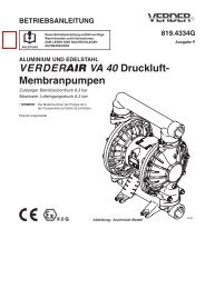
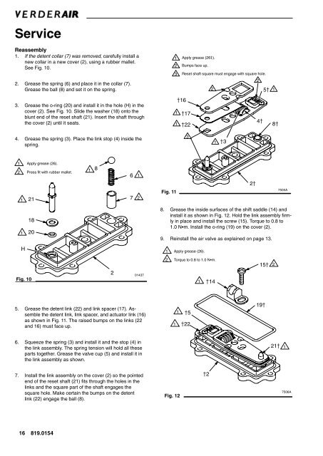
1. If the detent collar (7) was removed, carefully install a<br />
new collar in a new cover (2), using a rubber mallet.<br />
See Fig. <strong>10</strong>.<br />
2. Grease the spring (6) and place it in the collar (7).<br />
Grease the ball (8) and set it on the spring.<br />
3. Grease the o-ring (20) and install it in the hole (H) in the<br />
cover (2). See Fig. <strong>10</strong>. Slide the washer (18) onto the<br />
blunt end of the reset shaft (21). Insert the shaft through<br />
the cover (2) until it seats.<br />
1 Apply grease (26).<br />
2 Bumps face up.<br />
3 Reset shaft square must engage with square hole.<br />
2<br />
2<br />
5<br />
16<br />
1 17<br />
1 22<br />
4<br />
1<br />
8<br />
4. Grease the spring (3). Place the link stop (4) inside the<br />
spring.<br />
3<br />
1<br />
3<br />
1<br />
2<br />
1<br />
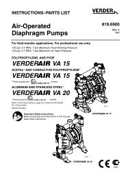
Apply grease (26).<br />
Press fit with rubber mallet.<br />
21<br />
1<br />
8<br />
6<br />
7<br />
1<br />
2<br />
Fig. 11<br />
2<br />
7505A<br />
1<br />
18<br />
20<br />
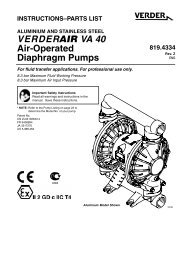
8. Grease the inside surfaces of the shift saddle (14) and<br />
install it as shown in Fig. 12. Hold the link assembly firmly<br />
in place and install the screw (15). Torque to 0.8 to<br />
1.0 Nm. Install the o-ring (19) on the cover (2).<br />
9. Reinstall the air valve as explained on page 13.<br />
H<br />
1<br />
Apply grease (26).<br />
Fig. <strong>10</strong><br />
2<br />
01437<br />
2<br />
Torque to 0.8 to 1.0 Nm.<br />
1 14<br />
15<br />
2<br />
5. Grease the detent link (22) and link spacer (17). Assemble<br />
the detent link, link spacer, and actuator link (16)<br />
as shown in Fig. 11. The raised bumps on the links (22<br />
and 16) must face up.<br />
1 5<br />
1 22<br />
19<br />
6. Squeeze the spring (3) and install it and the stop (4) in<br />
the link assembly. The spring tension will hold all these<br />
parts together. Grease the valve cup (5) and install it in<br />
the link assembly as shown.<br />
21<br />
1<br />
7. Install the link assembly on the cover (2) so the pointed<br />
end of the reset shaft (21) fits through the holes in the<br />
links and the square part of the shaft engages the<br />
square hole. Make certain the bumps on the detent<br />
link (22) engage the ball (8).<br />
Fig. 12<br />
2<br />
7506A<br />
16 819.0154