
You also want an ePaper? Increase the reach of your titles
YUMPU automatically turns print PDFs into web optimized ePapers that Google loves.
Installation<br />
Changing the Orientation of the Fluid Inlet and<br />
Outlet Ports<br />
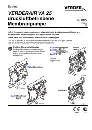
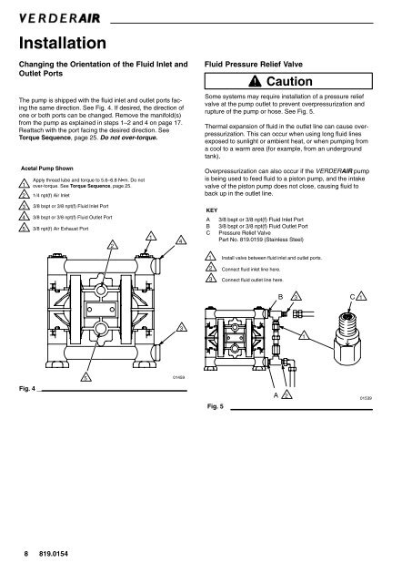
The pump is shipped with the fluid inlet and outlet ports facing<br />
the same direction. See Fig. 4. If desired, the direction of<br />
one or both ports can be changed. Remove the manifold(s)<br />
from the pump as explained in steps 1–2 and 4 on page 17.<br />
Reattach with the port facing the desired direction. See<br />
Torque Sequence, page 25. Do not over-torque.<br />
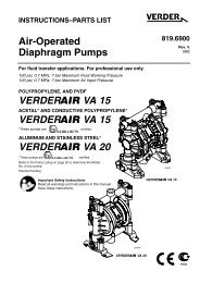
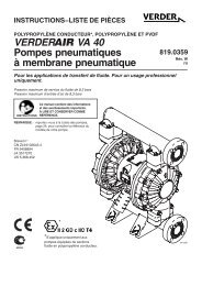
Acetal Pump Shown<br />
1<br />
Apply thread lube and torque to 5.6–6.8 Nm. Do not<br />
over-torque. See Torque Sequence, page 25.<br />
2 1/4 npt(f) <strong>Air</strong> Inlet<br />
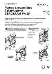
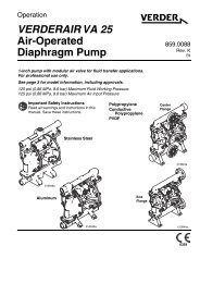
Fluid Pressure Relief Valve<br />
Caution<br />
Some systems may require installation of a pressure relief<br />
valve at the pump outlet to prevent overpressurization and<br />
rupture of the pump or hose. See Fig. 5.<br />
Thermal expansion of fluid in the outlet line can cause overpressurization.<br />
This can occur when using long fluid lines<br />
exposed to sunlight or ambient heat, or when pumping from<br />
a cool to a warm area (for example, from an underground<br />
tank).<br />
Overpressurization can also occur if the <strong>VERDER</strong>AIR pump<br />
is being used to feed fluid to a piston pump, and the intake<br />
valve of the piston pump does not close, causing fluid to<br />
back up in the outlet line.<br />
3 3/8 bspt or 3/8 npt(f) Fluid Inlet Port<br />
4 3/8 bspt or 3/8 npt(f) Fluid Outlet Port<br />
5 3/8 npt(f) <strong>Air</strong> Exhaust Port<br />
2<br />
1<br />
4<br />
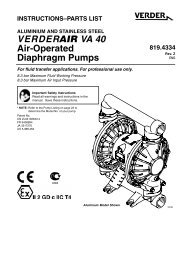
KEY<br />
A 3/8 bspt or 3/8 npt(f) Fluid Inlet Port<br />
B 3/8 bspt or 3/8 npt(f) Fluid Outlet Port<br />
C Pressure Relief Valve<br />
Part No. 819.0159 (Stainless Steel)<br />
1<br />
Install valve between fluid inlet and outlet ports.<br />
2 Connect fluid inlet line here.<br />
3<br />
Connect fluid outlet line here.<br />
B 3<br />
C 1<br />
3<br />
1<br />
5<br />
01459<br />
Fig. 4<br />
Fig. 5<br />
A<br />
2<br />
01539<br />
8 819.0154