You also want an ePaper? Increase the reach of your titles
YUMPU automatically turns print PDFs into web optimized ePapers that Google loves.
Service<br />
Tools Required<br />
<br />
<br />
<br />
Torque wrench<br />
13 mm socket wrench<br />
O-ring pick<br />
Ball Check Valves<br />
NOTE: A Fluid Section Repair Kit is available. See page 21<br />
for the correct kit. Parts included in the kit are marked<br />
with an asterisk, for example (301*). Use all the parts<br />
in the kit for the best results. Always replace the<br />
o-rings (<strong>10</strong>8) with new ones whenever the old ones<br />
are removed.<br />
Warning<br />
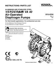
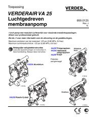
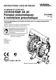
<strong>10</strong>. Reassemble the outlet ball checks in the top of the<br />
pump, following all notes in Fig. 13. Be sure the ball<br />
checks are assembled exactly as shown. To avoid<br />
pump leakage, run your finger over the o-rings (<strong>10</strong>8) and<br />
ensure that they are seated properly.<br />
11. Install the top manifold (<strong>10</strong>2) and four nuts (<strong>10</strong>6). Torque<br />
to 5.6–6.8 Nm. Do not over-torque. See Torque Sequence,<br />
page 25.<br />
<strong>10</strong>6<br />
4 5<br />
<strong>10</strong>4<br />
1<br />
<strong>10</strong>2<br />
6<br />
To reduce the risk of serious injury whenever you are<br />
instructed to relieve pressure, always follow the Pressure<br />
Relief Procedure on page <strong>10</strong>.<br />
1. Relieve the pressure. Disconnect all hoses. Remove<br />
the pump from its mounting.<br />
2. Using a 1/2” socket wrench, remove the nuts (<strong>10</strong>6) holding<br />
the top manifold (<strong>10</strong>2) to the covers (<strong>10</strong>1). Lift the<br />
manifold off the pump. See Fig. 13.<br />
3. Remove the outer o-ring (<strong>10</strong>8), ball guide (202),<br />
ball (301), seat (201), and inner o-ring (<strong>10</strong>8) from each of<br />
the covers.<br />
<strong>10</strong>8*<br />
202*<br />
301*<br />
201*<br />
<strong>10</strong>8*<br />
<strong>10</strong>1<br />
3<br />
2<br />
4. Turn the pump over. Pull the tie rods (<strong>10</strong>4) out of the<br />
pump, leaving the four nuts (<strong>10</strong>6) on the rods. Remove<br />
the feet (<strong>10</strong>7) and lower manifold (<strong>10</strong>2).<br />
5. Remove the outer o-ring (<strong>10</strong>8), seat (201), ball (301), ball<br />
guide (202), and inner o-ring (<strong>10</strong>8) from each of the<br />
covers (<strong>10</strong>1).<br />
6. Clean all parts and inspect for wear or damage. Replace<br />
parts as needed.<br />
7. Reassemble the intake ball checks in the bottom of the<br />
pump, following all notes in Fig. 13. Be sure the ball<br />
checks are assembled exactly as shown.<br />
8. Set the lower manifold (<strong>10</strong>2) and feet (<strong>10</strong>7) in place on<br />
the bottom of the pump.<br />
9. Insert the long threads of each rod (<strong>10</strong>4) through the feet<br />
and lower manifold. Push the rods up through the<br />
covers (<strong>10</strong>1) until the nut (<strong>10</strong>6) on the end of the rods<br />
bottoms on the foot. Make sure the rods are pushed all<br />
the way through. Turn the pump upright (the rods are a<br />
slight interference fit and will hold the pump parts securely<br />
in place).<br />
1<br />
2<br />
3<br />
4<br />
5<br />
Fig. 13<br />
Apply thread lubricant.<br />
Flat side faces ball.<br />
Beveled end up.<br />
Torque to 5.6–6.8 Nm. See<br />
Torque Sequence, page 25.<br />
Do not over-torque.<br />
6 Long threads at top.<br />
<strong>10</strong>8*<br />
202* 3<br />
301*<br />
201* 2<br />
<strong>10</strong>8*<br />
<strong>10</strong>2<br />
<strong>10</strong>7<br />
<strong>10</strong>6<br />
4 5<br />
02457B<br />
819.0154 17