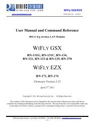
WIFLY GSX WIFLY EZX
WiFly GSX/EZX
WiFly GSX/EZX
- No tags were found...

Create successful ePaper yourself
Turn your PDF publications into a flip-book with our unique Google optimized e-Paper software.
WiFly <strong>GSX</strong>/<strong>EZX</strong><br />
www.rovingnetworks.com WiFly-RN-UM 4/8/2011<br />
User Manual and Command Reference<br />
802.11 b/g wireless LAN Modules<br />
<strong>WIFLY</strong> <strong>GSX</strong><br />
RN-131G, RN-131C, RN-134,<br />
RN-121, RN-123 & RN-125, RN-370<br />
<strong>WIFLY</strong> <strong>EZX</strong><br />
RN-171, RN-174<br />
Firmware Version 2.23<br />
April 3 rd 2011<br />
Copyright © 2011 Roving Networks, Inc. All Rights Reserved.<br />
The contents of this document can be changed by Roving networks without prior notice and do not<br />
constitute any binding undertakings from Roving networks. Roving Networks is not responsible under any<br />
circumstances for direct, indirect, unexpected or consequent damage that is caused by this document.<br />
809 University Avenue • Los Gatos, CA 95032 • Tel (408) 395-6539 • info@RovingNetworks.com<br />
~ 1 ~
WiFly <strong>GSX</strong>/<strong>EZX</strong><br />
www.rovingnetworks.com WiFly-RN-UM 4/8/2011<br />
Table of Contents<br />
1. Introduction ............................................................................................................................................... 4<br />
2. Overview ................................................................................................................................................... 4<br />
3. Configuration ............................................................................................................................................. 6<br />
3.1. Entering Command Mode ................................................................................................................. 6<br />
3.2. Remote configuration using ADHOC mode ..................................................................................... 7<br />
4. WiFly Command Reference ...................................................................................................................... 9<br />
4.1. Command Syntax .............................................................................................................................. 9<br />
4.2. Command Organization .................................................................................................................... 9<br />
5. SET Commands ....................................................................................................................................... 11<br />
5.1. Adhoc Parameters ........................................................................................................................... 11<br />
5.2. Broadcast Parameters ...................................................................................................................... 11<br />
5.3. COMM Parameters ......................................................................................................................... 12<br />
5.4. DNS Parameters .............................................................................................................................. 13<br />
5.5. FTP Parameters ............................................................................................................................... 13<br />
5.6. IP Parameters .................................................................................................................................. 14<br />
5.7. Optional Parameters ........................................................................................................................ 16<br />
5.8. System Parameters .......................................................................................................................... 17<br />
5.9. Time Server Parameters .................................................................................................................. 20<br />
5.10. UART Parameters ........................................................................................................................... 20<br />
5.11. WLAN Parameters .......................................................................................................................... 22<br />
5.12. Sensor Parameters ........................................................................................................................... 26<br />
6. Get Commands ........................................................................................................................................ 27<br />
7. Status Commands .................................................................................................................................... 28<br />
8. Action Commands ................................................................................................................................... 29<br />
9. File IO Commands .................................................................................................................................. 31<br />
10. Advanced features and Settings ........................................................................................................... 32<br />
10.1. System Timers and Auto Connect Timers ...................................................................................... 33<br />
Opening a TCP Connection: ........................................................................................................................ 35<br />
10.2. Wake on Sensor Input ..................................................................................................................... 36<br />
10.3. Wake on UART .............................................................................................................................. 37<br />
10.4. UART Receiver, RTS/CTS Hardware Flow Control ..................................................................... 37<br />
10.5. Setting GPIO direction, Alternate Functions and Disabling LEDs ................................................ 38<br />
10.6. Setting Debug Print levels .............................................................................................................. 42<br />
10.7. Using the Real Time Clock Function ............................................................................................. 44<br />
10.8. Time Stamping Packets .................................................................................................................. 45<br />
11. Sending data using UDP ................................................................................................................. 46<br />
11.1. Overview ......................................................................................................................................... 46<br />
11.2. UDP Auto Pairing ........................................................................................................................... 47<br />
11.3. UDP Retry ....................................................................................................................................... 47<br />
11.4. Using the UDP Broadcast function ................................................................................................. 47<br />
12. Joining Networks and Making Connections ........................................................................................ 49<br />
12.1. Associate with a network access point ........................................................................................... 49<br />
12.2. Making Connections ....................................................................................................................... 50<br />
12.3. Setting up Automatic Connections ................................................................................................. 51<br />
809 University Avenue • Los Gatos, CA 95032 • Tel (408) 395-6539 • info@RovingNetworks.com<br />
~ 2 ~
WiFly <strong>GSX</strong>/<strong>EZX</strong><br />
www.rovingnetworks.com WiFly-RN-UM 4/8/2011<br />
12.4. Controlling Connections using PIO5 and PIO6 .............................................................................. 51<br />
12.5. Using DNS settings ......................................................................................................................... 52<br />
12.6. Utilizing the Backup IP address/connect function .......................................................................... 52<br />
13. Using HTML client feature .................................................................................................................. 53<br />
13.1. Built-in HTML Client Modes ......................................................................................................... 54<br />
13.2. Automatically connect to web server .............................................................................................. 55<br />
13.3. Automatically connect to web server on uart data .......................................................................... 55<br />
13.4. Posting binary data: ........................................................................................................................ 56<br />
13.5. Auto posting sensor data: ................................................................................................................ 56<br />
13.6. Examples using the HTML client ................................................................................................... 57<br />
14. Firmware Upgrade over FTP ................................................................................................................ 60<br />
14.1. FTP Upload and Upgrade ............................................................................................................... 60<br />
15. FTP Client ....................................................................................................................................... 62<br />
15.1. Creating and retrieving files form FTP server using the WiFly module ........................................ 62<br />
15.1.1. Creating files on FTP server ........................................................................................................... 62<br />
15.1.2. Retrieving a file from FTP server ................................................................................................... 63<br />
16. Adhoc Networking Mode ..................................................................................................................... 64<br />
16.1. Infrastructure and adhoc comparison .............................................................................................. 64<br />
16.2. Configuring adhoc mode ................................................................................................................ 64<br />
16.3. Scanning for APs in Adhoc mode ................................................................................................... 66<br />
17. Analog Sensor Capability ..................................................................................................................... 67<br />
17.1. Automatic sampling of sensor pins: ................................................................................................ 68<br />
17.2. Using the Built In Sensor Power ..................................................................................................... 68<br />
18. Default Configuration Settings as of version 2.23 firmware ................................................................ 70<br />
18.1. Restoring Default configuration settings: ....................................................................................... 72<br />
19. Boot-up Timing Values ......................................................................................................................... 73<br />
20. Supported Access Points ...................................................................................................................... 74<br />
21. Release Notes ....................................................................................................................................... 75<br />
21.1. Known problems ............................................................................................................................. 75<br />
21.2. Current Firmware features and fixes .............................................................................................. 75<br />
809 University Avenue • Los Gatos, CA 95032 • Tel (408) 395-6539 • info@RovingNetworks.com<br />
~ 3 ~
WiFly <strong>GSX</strong>/<strong>EZX</strong><br />
www.rovingnetworks.com WiFly-RN-UM 4/8/2011<br />
1. Introduction<br />
This user guide is applicable to the RN-131 and the RN-171 modules and finished products designed by<br />
Roving Networks using these modules. While there are some hardware differences, the same ASCII<br />
command set applies to the RN-131 and the RN-171 modules.<br />
More details on the hardware differences between the RN-131 and the RN-171 module can be found here.<br />
In terms of the firmware, certain specific commands apply to either the RN-131 or the RN-171 module.<br />
Command Description RN-171 RN-131<br />
set wlan tx Sets the TX output power YES NO<br />
set wlan external <br />
Selects the antenna (on-board chip antenna v/s<br />
U.FL. connector)<br />
NO YES<br />
For detailed hardware specifications on the RN-131 and RN-171, please refer to their respective data sheets.<br />
2. Overview<br />
The “WiFly” radio module is a complete standalone embedded wireless LAN access device. The device<br />
has on board TCP/IP stack and applications, requiring only 4 pins (POWER, TX, RX, GND) to design in.<br />
Once initial configuration is set, the radio can automatically access the Wi-Fi network and send/receive<br />
serial data over UART.<br />
<br />
<br />
<br />
<br />
<br />
<br />
<br />
<br />
<br />
<br />
<br />
<br />
Fully Qualified and Wi-Fi Certified 2.4GHz IEEE 802.11b/g transceiver<br />
Ultra-low power:<br />
o RN-131: 4uA sleep, 35mA Rx, 210m Tx at 18dBm (TX power not configurable)<br />
o RN-171: 4uA sleep, 35mA Rx, 185 mA Tx at 12dBm (Tx power configurable)<br />
Small, compact surface mount module<br />
Antenna Options:<br />
o RN-131: On board ceramic chip antenna and U.FL connector for external antenna<br />
o RN-171: RF pad<br />
8 Mbit flash memory and 128 KB RAM<br />
UART and SPI slave hardware interfaces<br />
10 general purpose digital I/O<br />
8 analog inputs (14 bit, 400mV)<br />
Real-time clock for wakeup and time stamping/data logging<br />
Accepts 3.3V regulated or 2-3V battery with on board boost regulators<br />
Supports Adhoc and Infrastructure mode connections<br />
On board TCP/IP stack<br />
809 University Avenue • Los Gatos, CA 95032 • Tel (408) 395-6539 • info@RovingNetworks.com<br />
~ 4 ~
WiFly <strong>GSX</strong>/<strong>EZX</strong><br />
www.rovingnetworks.com WiFly-RN-UM 4/8/2011<br />
<br />
<br />
Wi-Fi Alliance certified for WPA2-PSK<br />
FCC / CE/ ICS certified and RoHS compliant<br />
Features<br />
<br />
<br />
<br />
<br />
<br />
<br />
<br />
<br />
<br />
<br />
Host Data Rate up to 1 Mbps for UART, 2 Mbps over SPI slave<br />
Memory 128 KB RAM, 2 MB ROM, 2 KB battery-backed memory, 8 Mbit Flash.<br />
Intelligent, built-in power management with programmable wakeup<br />
Can be powered from regulated 3.3VDC source or 2.0-3.0V batteries<br />
Real time clock for time stamping, auto-sleep and auto-wakeup modes<br />
Configuration over UART or wireless interfaces using simple ASCII commands<br />
Over the air firmware upgrade (FTP), and data file upload.<br />
Secure WiFi authentication WEP-128, WPA-PSK (TKIP), WPA2-PSK (AES).<br />
Built in networking applications: DHCP client, DNS client, ARP, ICMP ping, FTP, TELNET,<br />
HTTP, UDP, TCP<br />
802.11 power save and roaming functions<br />
809 University Avenue • Los Gatos, CA 95032 • Tel (408) 395-6539 • info@RovingNetworks.com<br />
~ 5 ~
WiFly <strong>GSX</strong>/<strong>EZX</strong><br />
www.rovingnetworks.com WiFly-RN-UM 4/8/2011<br />
3. Configuration<br />
3.1. Entering Command Mode<br />
There are two modes in the WiFly module, namely data mode and command mode. In data mode, the<br />
module is ready to either accept incoming connections or initiate outgoing connections. To configure the<br />
parameters and/or to view the current configuration, the module must be put into command mode (also<br />
called configuration mode). At any given time, the module will either be in command mode or in data<br />
mode.<br />
Upon power up, the device will be in data mode. To enter command mode, exactly the escape sequence (set<br />
to three characters, $$$ by default) must be sent. The device will respond with CMD indicating it is in<br />
command mode.<br />
NOTE: There is no carriage return () after the $$$ to enter command mode.<br />
For example: To enter command mode from data mode, you need to send<br />
$$$ //The module will respond with CMD indicating it is in command mode.<br />
$$$ //The module may not enter command mode<br />
NOTE: There is a 250ms buffer before and after the escape sequence. If any characters are sent before or<br />
after the escape sequence within this interval of 250ms, the WiFly module will treat it as data and pass it<br />
over the TCP or UDP socket. It will not enter command mode.<br />
While in command mode, the device will accept ASCII bytes as commands. Each command ends with a<br />
carriage return . To exit command mode, send exit. The device will respond with EXIT<br />
indicating that it has exited command mode and switched into data mode.<br />
Parameters, such as the SSID, channel, IP address, Serial Port settings, and all other settings can be viewed<br />
and configured in command mode.<br />
ASCII characters can be sent through a terminal emulator connected to the UART or via Telnet. When<br />
using the UART interface, communications settings should match the stored settings used by the WiFly<br />
module. The default is 9600 baudrate, 8 bits, No Parity, 1 stop bit, and hardware flow control disabled.<br />
Please DO NOT use HyperTerminal. Use TeraTerm as your terminal emulator. TeraTerm can be<br />
downloaded from our website: http://www.rovingnetworks.com/support<br />
809 University Avenue • Los Gatos, CA 95032 • Tel (408) 395-6539 • info@RovingNetworks.com<br />
~ 6 ~
WiFly <strong>GSX</strong>/<strong>EZX</strong><br />
www.rovingnetworks.com WiFly-RN-UM 4/8/2011<br />
Type $$$ in the terminal emulator. You should see CMD returned to you. This will verify that your cable<br />
and comm. settings are correct. Most valid commands will return an AOK response, and invalid ones will<br />
return an ERR description.<br />
To exit command mode, type “exit“.<br />
NOTE: You can enter command mode locally over the UART interface at any time when not connected,<br />
and also when connected if the appropriate settings are enabled.<br />
When the WiFly <strong>GSX</strong> module is powered up, it tries to auto associate to the Access Point stored in the<br />
config settings. If for some reason the module cannot find the Access Point, by default it goes into auto<br />
association mode and gets busy scanning and trying to join a network. This may cause the UART to become<br />
unresponsive for a brief amount of time and you may lose the data sent to the module while the module is in<br />
this “not associated” state making it difficult to get into command mode and configure the module<br />
Firmware version 2.21 and later fixes this issue. The auto-join feature is disabled when in command mode.<br />
This makes it easy to configure the module. Auto-join will re-enable when you exit out of command mode.<br />
The auto join feature can be disabled by setting the set wlan join 0. This will prevent the WiFly <strong>GSX</strong><br />
module to attempt to associate to a network that does not exist.<br />
Another alternative is to boot the module in adhoc mode by using the PIO9 adhoc/factory reset jumper. If<br />
this is high on power up, the module will not associate to any network; it will use the temporary adhoc<br />
mode. When in adhoc mode, you can configure the network settings.<br />
3.2. Remote configuration using ADHOC mode<br />
Using adhoc mode to configure the device eliminates the need for the module to be associated with a<br />
network access point. In adhoc mode the module creates it own “on demand” network that you can<br />
connect to via your computer like you would to any other network.<br />
To enable adhoc mode via hardware set PIO9 high (3.3V) at power up. On the RN-134 development board,<br />
GPIO9 is on the J1 jumper block. On the RN-174 development board, GPIO9 is on the J8 jumper. When the<br />
module powers up with PIO9 set high, the WiFly module creates an adhoc network with the following<br />
SSID: WiFly-<strong>GSX</strong>-XX, where XX is the final two bytes of the devices MAC address<br />
Channel: 1<br />
DHCP: OFF<br />
IP address: 169.254.1.1<br />
Netmask: 255.255.0.0<br />
With the adhoc jumper in place the above settings override the current saved configuration settings.<br />
809 University Avenue • Los Gatos, CA 95032 • Tel (408) 395-6539 • info@RovingNetworks.com<br />
~ 7 ~
WiFly <strong>GSX</strong>/<strong>EZX</strong><br />
www.rovingnetworks.com WiFly-RN-UM 4/8/2011<br />
From your computer, connect to the WiFly-<strong>GSX</strong>-XX network. This is an open network that does not<br />
require a pass phrase or pass key. Currently the WiFly only supports OPEN mode for creating adhoc<br />
networks.<br />
NOTE: It may take a couple of minutes for Auto IP in Windows to assign an IP address and connect to the<br />
network. You can check IP address of your Windows computer by running the ipconfig command in the<br />
command window. If connected, this command will show you the IP address and net mask for your<br />
computer.<br />
The IP address assigned by Auto IP must be on the subnet 169.254.x.y subnet otherwise the WiFly <strong>GSX</strong><br />
module will not be accessible.<br />
NOTE: If your machine has both wireless and wired interface hardware you may need to disable the wired<br />
LAN interface hardware before connecting to the adhoc network. If the wired LAN is enabled, the<br />
computer may assign an IP address that is not on the same subnet as the WiFly module.<br />
Once connected and you have a good IP address, telnet into the WiFly module on port 2000<br />
telnet 169.254.1.1 2000<br />
You should see the response *HELLO*<br />
You can now enter command mode and configure the module.<br />
809 University Avenue • Los Gatos, CA 95032 • Tel (408) 395-6539 • info@RovingNetworks.com<br />
~ 8 ~
WiFly <strong>GSX</strong>/<strong>EZX</strong><br />
www.rovingnetworks.com WiFly-RN-UM 4/8/2011<br />
4. WiFly Command Reference<br />
4.1. Command Syntax<br />
Commands begin with a keyword, and have optional additional parameters, generally space delimited.<br />
Commands and options are case sensitive. Hex input data can be upper or lower case. String text data, such<br />
as SSID is also case sensitive.<br />
The first command is fully decoded and must be complete. Other command parameters can be shorted by<br />
using only the first character.<br />
For example,<br />
set uart baudrate 115200 is valid,<br />
set uart b 115200 is also valid,<br />
set u b 115200<br />
is also valid, however,<br />
s uart baudrate 115200<br />
is NOT valid.<br />
Numbers can be entered as either decimal, (like 115200 above) or HEX. To enter HEX, use 0x.<br />
For example, the HEX value FF would be entered as 0xFF.<br />
4.2. Command Organization<br />
Commands fall into 5 general categories:<br />
SET COMMANDS<br />
GET COMMANDS<br />
STATUS COMMANDS<br />
ACTION COMMANDS<br />
FILE IO COMMANDS<br />
Take effect immediately, permanently (when save command is issued).<br />
Retrieve the permanently stored information for display to user.<br />
See what is going on with the interface, IP status, etc.<br />
Perform action such as scan, connect, disconnect, etc.<br />
Upgrade, load and save configuration, delete files, etc.<br />
NOTE: You must save any changes made or the module will load the previous settings upon reboot or<br />
power up. Configuration is saved using the save command.<br />
When the system boots, all configuration data is loaded into RAM variables from the file called “config”.<br />
The set commands actually only modify the RAM copy of variables in the system. In general, the IP,<br />
809 University Avenue • Los Gatos, CA 95032 • Tel (408) 395-6539 • info@RovingNetworks.com<br />
~ 9 ~
WiFly <strong>GSX</strong>/<strong>EZX</strong><br />
www.rovingnetworks.com WiFly-RN-UM 4/8/2011<br />
WLAN and UART settings need a save and reboot to take effect, since they operate at boot up time. For<br />
example you only associate set the channel and get your ip address once at power up.<br />
Most of the other commands take effect immediately like the COMM settings and timers. This allows<br />
temporary change of parameters “on the fly” to test features, minimizes power usage and saves on flash rewrite<br />
cycles.<br />
Once all configuration is complete, the user must save the settings using the save command to store the<br />
configuration data, otherwise it will not take effect upon reboot or reset. Multiple configurations can be<br />
stored by using the save command and these configurations can be loaded using the load<br />
command.<br />
809 University Avenue • Los Gatos, CA 95032 • Tel (408) 395-6539 • info@RovingNetworks.com<br />
~ 10 ~
WiFly <strong>GSX</strong>/<strong>EZX</strong><br />
www.rovingnetworks.com WiFly-RN-UM 4/8/2011<br />
5. SET Commands<br />
These commands begin with “set”. There are 6 major categories.<br />
Adhoc<br />
Broadcast<br />
COMM<br />
DNS<br />
FTP<br />
IP<br />
Option<br />
Sys<br />
Time<br />
UART<br />
WLAN<br />
controls the adhoc parameters<br />
controls the broadcast hello/heartbeat UDP message<br />
communication and data transfer, timers, matching characters<br />
DNS host and domain<br />
FTP host address and login information<br />
IP settings<br />
optional and not frequently used parameters<br />
system settings such as sleep and wake timers<br />
timer server settings<br />
serial port settings such as baudrate and parity<br />
wireless interface settings, such as ssid, chan, and security options<br />
5.1. Adhoc Parameters<br />
set adhoc beacon sets the adhoc beacon interval in milliseconds. Default is 100.<br />
set adhoc probe <br />
sets the adhoc probe timeout in seconds. This is the number of seconds<br />
waiting for probe responses before declaring, “ADHOC is lost” and<br />
disabling the network interface. Default is 60.<br />
5.2. Broadcast Parameters<br />
set broadcast address sets the address to which the UDP hello/heartbeat message is sent. The<br />
default address is 255.255.255.255<br />
set broadcast interval sets the interval at which the hello/heartbeat UDP message is sent.<br />
Interval is specified in seconds. The value is a mask that is compared to a<br />
free running seconds counter. For example if interval = 0x7, a packet will<br />
be sent every 8 seconds. The minimum interval value is 1 (every 2<br />
seconds) and max value is 0xff (every 256 seconds). Setting the interval<br />
value to zero disables sending UDP broadcast messages. Default interval<br />
is 7.<br />
set broadcast port <br />
sets the port number to which the UDP hello/heartbeat message is sent.<br />
Default port is 55555.<br />
809 University Avenue • Los Gatos, CA 95032 • Tel (408) 395-6539 • info@RovingNetworks.com<br />
~ 11 ~
WiFly <strong>GSX</strong>/<strong>EZX</strong><br />
www.rovingnetworks.com WiFly-RN-UM 4/8/2011<br />
5.3. COMM Parameters<br />
set comm $ <br />
set comm close <br />
set comm open <br />
set comm remote <br />
set comm idle <br />
set comm match <br />
set comm size <br />
sets character used to enter command mode. Typically used when “$$$” is<br />
a possible data string. Care should be taken when setting this to note the<br />
new character as once this setting is saved every subsequent reboot will<br />
ignore “$$$” and look for “”. Default is „$‟<br />
sets the ASCI string that is sent to the local UART when the TCP port is<br />
closed. If no string is desired, use 0 as the parameter. Max string<br />
length is 32 characters. Default is *CLOS*<br />
sets the string that is sent to the local UART when the TCP port is opened.<br />
If no string is desired, use 0 as the parameter. Max string length<br />
is 32 characters. Default is *OPEN*<br />
sets the string that is sent to the remote TCP client when the TCP port is<br />
opened. If no string is desired, use 0 as the parameter. Max string<br />
length is 32 characters. Default is *HELLO*<br />
sets the Idle Timer Value. This is the number of seconds with no transmit<br />
or receive data over TCP before the connection is closed automatically.<br />
Default is 0, never disconnect on idle.<br />
sets match character. An IP packet will be sent each time the match<br />
character appears in the data. Value is entered either as decimal (13) or<br />
hex (0xd) of the of the ASCII character. Default is 0, disabled. The match<br />
character is one of three ways to control TCP/IP packet forwarding. The<br />
others are comm size and comm timer. For more information refer to<br />
section 10.4 on UART Receiver.<br />
sets the flush size. An IP packet will be sent each time “value” bytes are<br />
received. Default is 64 bytes. It is recommended to set this value to the<br />
largest possible setting to maximize TCP/IP performance. Maximum<br />
value = 1420 (at 9600) bytes.<br />
NOTE: This value is set automatically when the baudrate is set, in an<br />
attempt to optimize the link. It is assumed that higher baudrates equates<br />
to more data and hence the flush size is increased.<br />
Flush size is one of three ways to control TCP/IP packet forwarding. The<br />
others are match character and timer. For more information refer to<br />
section 10.4 on UART Receiver.<br />
set comm time <br />
sets the flush timer. An IP packet will be sent if no additional bytes are<br />
received for “num” milliseconds. “num” is one milliseconds interval.<br />
809 University Avenue • Los Gatos, CA 95032 • Tel (408) 395-6539 • info@RovingNetworks.com<br />
~ 12 ~
WiFly <strong>GSX</strong>/<strong>EZX</strong><br />
www.rovingnetworks.com WiFly-RN-UM 4/8/2011<br />
Default is 10 (10 milliseconds). Setting this value to 0 will disable<br />
forwarding based on the flush timer.<br />
Flush timer is one of three ways to control TCP/IP packet forwarding.<br />
The others are match character and size. For more information refer to<br />
section 10.4 on UART Receiver.<br />
5.4. DNS Parameters<br />
set dns address <br />
set dns name <br />
set dns backup <br />
sets the IP address of the DNS sever. This is auto-set when using DHCP,<br />
and needs to be set in STATIC IP or Auto-IP modes.<br />
sets the name of the host for TCP/IP connections.<br />
sets the name of the backup host for TCP/IP connections.<br />
5.5. FTP Parameters<br />
set ftp addr <br />
set ftp dir <br />
set ftp filename <br />
set the IP address of the FTP server. By default, the IP address is set to<br />
Roving Networks‟ FTP server (208.109.78.34)<br />
sets the directory to use on the FTP server. Default is “public”. To<br />
read/write to sub-folders, use the “\” for your directory structure. For<br />
example, to read/write to the “test” sub-folder in “demo” directory, the<br />
command is set ftp dir demo\test. To root directory is set by using the<br />
period “.” To se the root directory, the command if set ftp dir .<br />
sets the name of the file transferred when issuing the ftp u command. The<br />
file here refers to the firmware image. If any file other than the firmware<br />
image is set, the WiFly module will download the file and then issue the<br />
UPDATE FAIL=3 error since it is not the firmware image.<br />
set ftp mode <br />
sets the ftp mode. Default is passive mode (mode =0x0). Setting<br />
mode=0x1 enables active mode.<br />
set ftp remote sets the ftp server remote port number (default is 21).<br />
set ftp time <br />
set ftp user <br />
sets the ftp timeout value. This timer is used to automatically close the<br />
FTP connection. The timer is 1/8 th of the actual value. For example, to set<br />
a timer of 5 seconds, the command is set ftp timer 40. To set the timer to<br />
10 seconds is set ftp timer 80<br />
sets the ftp user name for accessing the FTP server. Default is roving<br />
809 University Avenue • Los Gatos, CA 95032 • Tel (408) 395-6539 • info@RovingNetworks.com<br />
~ 13 ~
WiFly <strong>GSX</strong>/<strong>EZX</strong><br />
www.rovingnetworks.com WiFly-RN-UM 4/8/2011<br />
set ftp pass <br />
sets the ftp password for accessing the FTP server. Default is Pass123<br />
5.6. IP Parameters<br />
set ip address <br />
sets the IP address of the WiFly <strong>GSX</strong> module. If DHCP is turned on, the<br />
IP address is assigned and overwritten during association with the access<br />
point. IP addresses are “.” delimited.<br />
Example: set ip a 10.20.20.1<br />
set ip backup <br />
set ip dhcp <br />
sets a secondary host IP address. If the primary host IP is not reachable<br />
the module will try the secondary IP address if set.<br />
enable/disable DHCP mode. If enabled, the IP address, gateway, netmask,<br />
and DNS server are requested and set upon association with access point.<br />
Any current IP values are overwritten.<br />
DHCP Cache mode can reduce the time it takes the module to wake from<br />
deep sleep thus saving power. In cache mode, the lease time is checked<br />
and if not expired, the module uses the previous IP settings. If the lease<br />
has expired the module will attempt to associated and use DHCP to get the<br />
IP settings. DHCP cached IP address does not survive a power cycle or<br />
reset.<br />
Mode<br />
Protocol<br />
0 DHCP OFF, use stored static IP address<br />
1 DHCP ON, get IP address and gateway from AP<br />
2 Auto-IP, generally used with Adhoc networks<br />
DHCP cache mode, Uses previous IP address if<br />
3<br />
lease is not expired (lease survives reboot)<br />
4 Reserved for future use<br />
809 University Avenue • Los Gatos, CA 95032 • Tel (408) 395-6539 • info@RovingNetworks.com<br />
~ 14 ~
WiFly <strong>GSX</strong>/<strong>EZX</strong><br />
www.rovingnetworks.com WiFly-RN-UM 4/8/2011<br />
set ip flags Set TCP/IP functions. Value is a bit mapped register. Default = 0x7.<br />
Bit<br />
Function<br />
0 TCP connection status. See note below<br />
1 Bypass Nagle algorithm and use TCP_NODELAY<br />
2 TCP retry enabled (total of 96 packet retries)<br />
UDP RETRY (attempts retry if no ACK from<br />
3<br />
UDP)<br />
4 DNS host address caching enabled<br />
5 ARP table caching enabled<br />
6 UDP auto pairing enabled<br />
7 Add 8 byte timestamp to UDP or TCP packets<br />
NOTE: When the link to an associated to an access point is lost while a<br />
TCP connection is active, the TCP connection can be left in hung or<br />
inconsistent state. In some cases, the TCP connection will not recover. In<br />
version 2.20 and later, if the link to the access point is regained within 60<br />
seconds, the TCP connection will survive.<br />
With version 2.20 we have changed the operation of bit0 in the “ip flags”<br />
register. Previously this bit specified the TCP copy function, but controls<br />
the TCP socket function while associated on a network.<br />
If bit 0 is set (default = 0x7) TCP connections are kept open when<br />
the connection to the access point is lost.<br />
If bit 0 is cleared (by setting “set ip flags 0x6” for example) then<br />
when the connection to the access point is lost and TCP is<br />
connected, the connection will be closed.<br />
set ip gateway <br />
set ip host <br />
set ip localport <br />
set ip netmask <br />
set ip protocol <br />
sets the gateway IP address, If DHCP is turned on, the gateway IP address<br />
is assign and overwritten during association with the access point.<br />
sets the remote host IP address. This command is used for making<br />
connections from the WiFly module to a TCP/IP server at the IP address<br />
.<br />
sets the local port number.<br />
sets the network mask. If DHCP is turned on, the net mask is assign and<br />
overwritten during association with the access point.<br />
sets the IP protocol. Value is a bit mapped setting. To connect to the<br />
WiFly <strong>GSX</strong> module over TCP/IP such as Telnet the device must have the<br />
809 University Avenue • Los Gatos, CA 95032 • Tel (408) 395-6539 • info@RovingNetworks.com<br />
~ 15 ~
WiFly <strong>GSX</strong>/<strong>EZX</strong><br />
www.rovingnetworks.com WiFly-RN-UM 4/8/2011<br />
use the TCP Server protocol / bit 2 set. To accept both TCP and UDP use<br />
value = 3 (bit 1 and bit 2 set)<br />
Bit Position Protocol<br />
0 UDP<br />
1 TCP Server & Client (Default)<br />
2<br />
Secure (only receive packets with IP address<br />
matches the store host IP)<br />
3 TCP Client only<br />
4 HTTP client mode<br />
set ip remote <br />
sets the remote host port number.<br />
5.7. Optional Parameters<br />
set opt jointmr <br />
set opt format <br />
Join timer is the time in milliseconds the join function will wait for the an<br />
access point to complete the association process. This timer is also the<br />
timeout for the WPA handshaking process. Default is 1000.<br />
settings for HTTP client/web server value is a bitmapped register. See<br />
section on web server modes for more details.<br />
Bit Position<br />
0<br />
1<br />
2<br />
3<br />
4<br />
Function<br />
Automatically send HTML header based<br />
broadcast interval.<br />
Send users BINARY data (converted to ASCII<br />
hex )<br />
Sample the GPIO and ADC pins and format to<br />
ASCII hex<br />
Appends &id= < value>, where value is the<br />
device ID string set with set opt device <br />
Appends the following key value pairs to the<br />
HTTP message: &rtc=, &mac=, &bss= ,<br />
&bat=, &io=, &wake=,<br />
&seq=, where time is real<br />
time clock value in message as 32 bit HEX value<br />
in format aabbccddeeff, sequence number is a<br />
rolling counter of how many web posts have been<br />
sent<br />
809 University Avenue • Los Gatos, CA 95032 • Tel (408) 395-6539 • info@RovingNetworks.com<br />
~ 16 ~
WiFly <strong>GSX</strong>/<strong>EZX</strong><br />
www.rovingnetworks.com WiFly-RN-UM 4/8/2011<br />
set opt replace <br />
set opt deviceid <br />
set opt password <br />
replacement character for spaces. The replacement character is used when<br />
entering SSID and pass phrases that include space. This is used by the<br />
WiFly command parser only. Each occurrence of the replacement<br />
character is changed into a space. The default is “$” (0x24)<br />
Configurable Device ID - can be used for storing serial numbers, product<br />
name or other device information. This information is sent as part of the<br />
broadcast hello packet that is sent as a UDP. The current value can be<br />
shown with the “get option” or “show deviceid” commands. Max string<br />
size is 32 bytes. The default is “WiFly-<strong>GSX</strong>”.<br />
TCP connection password. Provides minimal authentication by requiring<br />
any remote device that connects to send and match a challenge .<br />
When set, all newly opened connections must first send the exact<br />
characters that match the stored password otherwise the WiFly module<br />
will close the connection. When the password is set the WiFly module<br />
sends the string “PASS?” to the remote host. All characters in the string<br />
must be sent in one TCP packet. Max string size is 32 bytes. To disable<br />
the password feature use string=0 which is the default.<br />
5.8. System Parameters<br />
set sys autoconn <br />
TCP mode: sets the auto connect timer. This command causes the module<br />
periodically connect to the stored remote host. The timer <br />
determines how often to connect to the stored remote host. Default=0<br />
Value Description<br />
0 Disable auto connect timer<br />
1 Connect to the stored host IMMEDIATELY upon<br />
power up or wake from sleep state<br />
2-254 Connect to a stored host every number of<br />
seconds<br />
255 Connect to a stored host IMMEDIATELY upon<br />
power up or wake from sleep state and go back to<br />
sleep IMMEDIATELY as soon as TCP connection<br />
is closed<br />
NOTE: To use the auto connect timer, the remote host‟ IP address and<br />
port must be stored in the WiFly module using the<br />
set ip host and set ip remote commands.<br />
set sys autosleep <br />
Sets the auto-sleep timer in UDP mode. If the protocol is set to UDP<br />
ONLY, this timer is used as a quick sleep function. Device will sleep<br />
809 University Avenue • Los Gatos, CA 95032 • Tel (408) 395-6539 • info@RovingNetworks.com<br />
~ 17 ~
WiFly <strong>GSX</strong>/<strong>EZX</strong><br />
www.rovingnetworks.com WiFly-RN-UM 4/8/2011<br />
milliseconds after transmission of the first UDP packet. Setting<br />
value to 0 disables the autosleep timer.<br />
set sys iofunc <br />
set sys mask <br />
set sys printlvl <br />
sets the IO port alternate functions. Bit-mapped value. For more details<br />
see section 10.5<br />
sets the IO port direction mask. Bit-mapped value. For more information<br />
see section 10.5<br />
Controls debug print messages. This configures the debug messages<br />
printed by the WiFly module on the UART. Default=1. Please refer<br />
section 10.6 on Setting Debug Print levels.<br />
Value<br />
Description<br />
Quiet mode. No messages printed when module wakes<br />
0<br />
up or powers up.<br />
1 All status messages<br />
Only critical NETWORK AP connection level status is<br />
2<br />
output, "Associated!" or "Disconnect from "<br />
DHCP and IP address status information. Once the<br />
configuration has been checked; this can then be turned<br />
4<br />
off so that these messages do not interfere with the<br />
data.<br />
0x4000 New scan format output<br />
Enables uart heartbeat message. See section 10.6.2 for<br />
0x10<br />
more details<br />
set sys output sets output GPIO pins to HIGH or LOW. This is a bit-mapped value.<br />
Optional mask only sets a subset of pins.<br />
For example, to toggle GPIO8 the commands are:<br />
set sys mask 0x21f0<br />
set sys output 0x0010 0x0010<br />
set sys output 0x0000 0x0010<br />
//set GPIO8 as output<br />
//drives GPIO8 HIGH<br />
//drives GPIO8 LOW<br />
set sys sleep <br />
sets the sleep timer. The sleep timer is the time in seconds after which the<br />
module goes to sleep. This timer is disabled during an open TCP<br />
connection. When the TCP connection is closed, the module counts down<br />
and puts the module in sleep state based on the value (in seconds). Setting<br />
the value= 0 disables the sleep counter and the module will not go into<br />
sleep based on this counter.<br />
809 University Avenue • Los Gatos, CA 95032 • Tel (408) 395-6539 • info@RovingNetworks.com<br />
~ 18 ~
WiFly <strong>GSX</strong>/<strong>EZX</strong><br />
www.rovingnetworks.com WiFly-RN-UM 4/8/2011<br />
NOTE: Be sure to set the wake timer if not using an external wake up<br />
signal before issuing the sleep timer or the module will never wake up.<br />
See section 10.1 for more details on using system timers<br />
set sys trigger The WiFly modules can wake up from sleep state using the sensor input 0,<br />
1, 2 and 3. This command sets the sensor input(s) to wake on (0-3). This<br />
is a bit-mapped value. Setting the value=0 disables wake on sensor<br />
inputs.<br />
The following table describes how the WiFly module can be woken on<br />
sensor input.<br />
Wake on sensor input Value Command<br />
0 1 set sys trigger 1<br />
1 2 set sys trigger 2<br />
2 4 set sys trigger 4<br />
3 8 set sys trigger 8<br />
Setting the trigger value to 0x20, will enable putting the module to sleep<br />
when GPIO8 is pulled high. To enable this feature, the command is<br />
set sys trigger 0x20. This command makes GPIO 8 an interrupt pin and puts<br />
the module to sleep as soon as it is pulled HIGH irrespective of the state in which<br />
the module is. Even if the module is joining a network or has an active TCP<br />
connection open, it will go to sleep immediately.<br />
This command is useful in cases such as when the module is failing to join<br />
a network because it is out of range (or any other reason) or if it is<br />
required to put the module to sleep really quick.<br />
NOTE: GPIO8 must be low on power up and stay low until it is<br />
desired to put the module to sleep.<br />
set sys value <br />
sets the default value of the GPIO outputs upon power up. The GPIOs that<br />
are configured as outputs can either be driven HIGH or LOW upon power<br />
up or when the module wakes from sleep. The default power up states can<br />
be set ONLY for the GPIOs set as outputs.<br />
Setting the GPIO value to 1 sets the default power-up state of that GPIO<br />
HIGH and setting the GPIO value to 0 sets the default power-up state to<br />
be LOW.<br />
To configure GPIO as outputs, use the set sys mask command.<br />
809 University Avenue • Los Gatos, CA 95032 • Tel (408) 395-6539 • info@RovingNetworks.com<br />
~ 19 ~
WiFly <strong>GSX</strong>/<strong>EZX</strong><br />
www.rovingnetworks.com WiFly-RN-UM 4/8/2011<br />
For Example, to configure power-up states of GPIO8 (output by default)<br />
the commands are:<br />
set sys value 0x0100<br />
set sys value 0x0000<br />
//sets GPIO8 HIGH upon power-up<br />
//sets GPIO8 LOW upon power-up<br />
NOTE: GPIOs 4, 5 and 6 are used by firmware to blink status LEDs. To<br />
set default power up states for these GPIOs, their use by the firmware has<br />
to be disabled first using the set sys iofunc 0x7 command.<br />
set sys wake <br />
sets the auto wake timer. The wake timer is the number of seconds after<br />
which the WiFly module will wake from sleep state. Setting value=0<br />
disables. See section on using system timers for more details.<br />
5.9. Time Server Parameters<br />
set time address <br />
set time port <br />
set time enable <br />
set time raw <br />
sets the time server address. (sNTP servers)<br />
sets the time server port number. Defaults to 123, which is almost always<br />
the sNTP server port.<br />
Enable or disable fetching time from the specified sNTP time server.<br />
Default=0= disabled. A value or 1 gets time only once on power up. Any<br />
value > 1 gets time continuously every minutes.<br />
Enables setting the RTC raw value from the console. This command sets<br />
the RTC in seconds which ticks at 32768 Hz.<br />
5.10. UART Parameters<br />
set uart baud set the UART baud rate. Valid settings are {2400, 4800, 9600, 19200,<br />
38400, 57600, 115200, 230400, 460800, 921600}.<br />
Example: “set u b 9600” sets the baud rate to 9600 baud.<br />
NOTE: the RS232 interface on the RN-134 does not work above 230400<br />
set uart instant <br />
This immediately changes the baudrate. This is useful when testing<br />
baudrate settings, or switching baudrate “on the fly” remotely while<br />
connected over TCP (Telnet). This setting does not affect configuration.<br />
Returns the AOK response, and then this command will exit command<br />
mode.<br />
809 University Avenue • Los Gatos, CA 95032 • Tel (408) 395-6539 • info@RovingNetworks.com<br />
~ 20 ~
WiFly <strong>GSX</strong>/<strong>EZX</strong><br />
www.rovingnetworks.com WiFly-RN-UM 4/8/2011<br />
In firmware version 2.22 and later, we fixed a bug wherein the WiFly<br />
module would not return an AOK over telnet. Now when this command is<br />
issued, it returns an AOK over Telnet and does not exit command mode.<br />
If used in local mode, the baud rate will change and the AOK will come<br />
out the NEW baud rate. It is possible if the host switches to the new baud<br />
rate right away it might catch see the AOK string (on the new baud rate).<br />
Depending on the baudrate it will take at least 10* bitrate for first char to<br />
come out<br />
set uart raw <br />
sets a RAW UART value. Used to set non-standard rates. The lowest<br />
possible baud rate is 2400.<br />
Example : “set u r 7200” sets the baud rate to 7200 baud.<br />
Using non standard raw baud rates (with hardware flow control) can be<br />
more useful at speeds as the micro controller interfaced to the module may<br />
be able to better match the uart speeds and get better results.<br />
The following raw baud rates are supported:<br />
Raw baud rate Comment<br />
458333 This is 460800<br />
500000 Raw baud rate<br />
550000 Raw baud rate<br />
611111 Raw baud rate<br />
687599 Raw baud rate<br />
785714 Raw baud rate<br />
916667 This is 921600<br />
1100000 Raw baud rate<br />
set uart flow <br />
sets the flow control mode. Default=0=Disabled, 1= hardware RTS/CTS.<br />
NOTE: Once flow control is enabled, it is important to properly<br />
drive the CTS pin (active LOW enabled) If CTS is HIGH, data will<br />
NOT be sent out the UART, and further configuration in command mode<br />
will be problematic as no response will be received.<br />
set uart mode <br />
sets the UART mode register. This is a bit-mapped value.<br />
Bit Position Function<br />
NOECHO - disables echo of RX data while in<br />
0<br />
command mode<br />
1 DATA TRIGGER makes connection on RX data<br />
809 University Avenue • Los Gatos, CA 95032 • Tel (408) 395-6539 • info@RovingNetworks.com<br />
~ 21 ~
WiFly <strong>GSX</strong>/<strong>EZX</strong><br />
www.rovingnetworks.com WiFly-RN-UM 4/8/2011<br />
2 Reserved for future use<br />
3 Enable Sleep on RX BREAK signal<br />
4 UART RX data buffer. See note below for details*<br />
*NOTE: When a TCP connection is closed, if there is RX data in the<br />
UART receiver, it is held until<br />
1) more chars come in, in which case it will get flushed, or<br />
2) no chars come in and a new connection is made, then the chars<br />
will get forwarded.<br />
If this setting is enabled (set uart mode 0x10), any unsent RX data is still<br />
in the buffer is flushed when a connection is closed.<br />
set uart tx <br />
Disables or enables the TX pin= PIO10 of the UART. Disable will set<br />
PIO10 to an INPUT with weak pulldown.<br />
NOTE: Due to an issue in the UART hardware, the UART does not support even or odd parity.<br />
5.11. WLAN Parameters<br />
set wlan auth Sets the authentication mode. Not needed unless using auto join mode 2.<br />
i.e. set wlan join 2<br />
Note: During association the WiFly module interrogates the Access Point<br />
and automatically selects the authentication mode.<br />
The current release of Wifly firmware supports these security modes:<br />
• WEP-128 (open mode only, NOT shared mode)<br />
• WPA2-PSK (AES only)<br />
• WPA1-PSK (TKIP only)<br />
• WPA-PSK mixed mode (some APs, not all are supported)<br />
Value Authentication Mode<br />
0 Open (Default)<br />
1 WEP-128<br />
2 WPA1<br />
3 Mixed WPA1 & WPA2-PSK<br />
4 WPA2-PSK<br />
5 Not Used<br />
6 Adhoc, Join any Adhoc network<br />
809 University Avenue • Los Gatos, CA 95032 • Tel (408) 395-6539 • info@RovingNetworks.com<br />
~ 22 ~
WiFly <strong>GSX</strong>/<strong>EZX</strong><br />
www.rovingnetworks.com WiFly-RN-UM 4/8/2011<br />
set wlan channel <br />
set wlan ext_antenna <br />
sets the wlan channel, 1-13 is the valid range for a fixed channel. If 0 is<br />
set, then scan is performed, using the ssid, for all the channels set in the<br />
channel mask.<br />
determines which antenna is active, use 0 for chip antenna, 1 for UF.L<br />
connector. Default = 0. Only one antenna is active at a time and the<br />
module must be power cycled after switching the antenna.<br />
NOTE: This command applies only to RN-131. This command is not<br />
applied to the RN-171. Issuing this command on the RN-171 will give an<br />
error message: ERR: Bad Args<br />
set wlan join <br />
sets the policy for automatically joining/associating with network access<br />
points. This policy is used when the module powers up, including wake<br />
up from the sleep timer.<br />
Value Policy<br />
0 Manual, do not try to join automatically<br />
1 Try to join the access point that matches the stored<br />
SSID, passkey and channel. Channel can be set to<br />
0 for scanning. (Default)<br />
2 Join ANY access point with security matching the<br />
stored authentication mode. This ignores the stored<br />
SSID and searches for the access point with the<br />
strongest signal. The channels searched can be<br />
limited by setting the channel mask.<br />
3 Reserved – Not used<br />
4 Create an Adhoc network, using stored SSID, IP<br />
address and netmask. Channel MUST be set.<br />
DHCP should be 0 (static IP) or set to Auto-IP with<br />
this policy. (unless another Adhoc device can act as<br />
DHCP server)<br />
This policy is often used instead of the hardware<br />
jumper to creat a custom Adhoc network<br />
set wlan hide <br />
Hides the WEP key and WPA passphrase. When set, displaying the wlan<br />
settings shows ****** for these fields. To unhide the passphrase or<br />
passkey, re-enter the key or passphrase using the set wlan key or set wlan<br />
passphrase command. Default = 0, don‟t hide.<br />
809 University Avenue • Los Gatos, CA 95032 • Tel (408) 395-6539 • info@RovingNetworks.com<br />
~ 23 ~
WiFly <strong>GSX</strong>/<strong>EZX</strong><br />
www.rovingnetworks.com WiFly-RN-UM 4/8/2011<br />
set wlan key <br />
sets the 128 bit WEP key. If you are using WPA or WPA2 you should<br />
enter a pass phrase with the set wlan passphase command. Key must be<br />
EXACTLY 13 bytes (26 ASCII chars). Data is expected in HEX format,<br />
“0x” should NOT be used here.<br />
Example : “set w k 112233445566778899AABBCCDD”<br />
Hex digits > 9 can be either upper or lower case.<br />
The Wifly <strong>GSX</strong> only supports “open” key mode, 128 bit keys for WEP.<br />
WEP-128, shared mode is not supported as it is known to be easily<br />
compromised and has been deprecated from the WiFi standards.<br />
set wlan linkmon <br />
sets the link monitor timeout threshold. If set to 1 or more, WiFly will<br />
scan once per second for the AP it is associated with. The value is the<br />
threshold of failed scans before the WiFly declares “AP is Lost”, deauthenticates.<br />
The WiFly will retry the association based on the join<br />
policy variable. A value of 5 is recommended, as some APs will not<br />
always respond to probes. Default is 0 (disabled). Without this feature,<br />
there is no way to detect an AP is no longer present until it becomes<br />
available again (if ever).<br />
set wlan mask <br />
set wlan num <br />
sets the wlan channel mask used for scanning channels with the auto-join<br />
policy 1 or 2, used when the channel is set to 0. Value is a bit-map where<br />
bit 0 = channel 1. Input for this command can be entered in decimal or<br />
hex if prefixed with 0x. Default value is 0x1FFF (all channels)<br />
sets the default WEP key to use. 1-4 is the valid range.<br />
Example : “set w n 2” sets the default key to 2.<br />
set wlan phrase <br />
sets the passphrase for WPA and WPA2 security modes. 1-64 chars. The<br />
passphrase can be alpha and numeric, and is used along with the SSID to<br />
generate a unique 32 byte Pre-shared key (PSK), which is then hashed into<br />
a 256 bit number. Changing either the SSID or this value re-calculates<br />
and stores the PSK.<br />
If exactly 64 chars are entered, it is assumed that this entry is already an<br />
ASCII HEX representation of the 32 byte PSK and the value is simply<br />
stored.<br />
For passphrases that contain spaces use the replacement character $<br />
instead of spaces. For example “my pass word” would be entered<br />
809 University Avenue • Los Gatos, CA 95032 • Tel (408) 395-6539 • info@RovingNetworks.com<br />
~ 24 ~
WiFly <strong>GSX</strong>/<strong>EZX</strong><br />
www.rovingnetworks.com WiFly-RN-UM 4/8/2011<br />
“my$pass$word”. The replacement character can be changed using the<br />
optional command set opt replace .<br />
Example : “set w p password” sets the phrase.<br />
set wlan rate <br />
sets the wireless data rate. Lowering the rate increases the effective range<br />
of the WiFly-<strong>GSX</strong> module. The value entered is mapped according to the<br />
following table:<br />
Value Wireless Data Rate<br />
0 1 Mbit/sec<br />
1 2 Mbit/sec<br />
2 5.5 Mbit/sec<br />
3 11 Mbit/sec<br />
4 - 7 Invalid<br />
8 6 Mbit/sec<br />
9 9 Mbit/sec<br />
10 12 Mbit/sec<br />
11 18 Mbit/sec<br />
12 24 Mbit/sec (default)<br />
13 36 Mbit/sec<br />
14 48 Mbit/sec<br />
15 54 Mbit/sec<br />
set wlan ssid <br />
sets the wlan ssid to associate with. 1-32 chars.<br />
NOTE: If the passphrase or ssid contain the SPACE ( „ „)<br />
characters, these can be entered using substitution via the “$” character.<br />
For example, if the ssid of the AP is “yellow brick road”<br />
You would enter “yellow$brick$road”<br />
Using the „get w” command will properly display the value:<br />
SSID=yellow brick road.<br />
set wlan tx <br />
Sets the Wi-Fi transmit power. Accepts value from 1-12 corresponding to<br />
1dBm to 12dBm. Default is 0 corresponding to 12dBm (max TX power).<br />
Setting the value to 0 or 12 sets the TX power to 12dBm<br />
NOTE: This command applies only to RN-171 module and not the RN-<br />
131. The transmit power on the RN-131 is fixed to 18dBm. Issuing this<br />
command on the RN-131 will return an error message, ERR: Bad Args<br />
809 University Avenue • Los Gatos, CA 95032 • Tel (408) 395-6539 • info@RovingNetworks.com<br />
~ 25 ~
WiFly <strong>GSX</strong>/<strong>EZX</strong><br />
www.rovingnetworks.com WiFly-RN-UM 4/8/2011<br />
set wlan window <br />
sets the IP maximum buffer window size. Default is 1460 bytes.<br />
5.12. Sensor Parameters<br />
set q sensor <br />
Bitmask value that determines which sensor pins to sample when sending<br />
data using the UDP broadcast packet, or the HTTP auto sample function.<br />
NOTE: The sensor pins variable has been changed from<br />
“set option sensor ” to set q sensor in ver 2.23<br />
set q power This register is used to automatically turn on the sensor power. This is a 8<br />
bit register with two 4 bit nibbles. If the top nibble is set, then power is<br />
applied upon power up and removed upon power down or sleep.<br />
If the bottom nibble is set, then power is applied when a sampling event<br />
occurs, for example:<br />
The UDP broadcast<br />
The auto web posting of sensor data<br />
The power is removed immediately after the sampling is complete.<br />
The values used for setting the power are described in the table below:<br />
Value Sensor pin voltage<br />
0 Turn off the sensor power<br />
1 GROUND the sensor pin<br />
2 1.2V internal regulated reference<br />
3 VBATT input pin<br />
4 3.3V output of on board regulator<br />
Example: To set the power to 1.2V automatically upon power up, the<br />
command would be set q power 0x20. To set sensor power to 1.2V when<br />
sampling event occurs, the command is set q power 0x02<br />
Example: To set the power to 3.3V automatically upon power up, the<br />
command would be set q power 0x40. To set sensor power to 3.3V when<br />
sampling event occurs, the command is set q power 0x04<br />
809 University Avenue • Los Gatos, CA 95032 • Tel (408) 395-6539 • info@RovingNetworks.com<br />
~ 26 ~
WiFly <strong>GSX</strong>/<strong>EZX</strong><br />
www.rovingnetworks.com WiFly-RN-UM 4/8/2011<br />
6. Get Commands<br />
These commands begin with “get”. They display the current values.<br />
get adhoc<br />
get broadcast<br />
get com<br />
get dns<br />
get everything<br />
get ftp<br />
get ip <br />
get mac<br />
get option<br />
get sys<br />
get time<br />
get wlan<br />
get uart<br />
ver<br />
display all adhoc settings.<br />
will display the broadcast UPD address, port and interval<br />
display comm. settings.<br />
display DNS settings.<br />
displays all configuration settings, useful for debug.<br />
display FTP settings.<br />
display IP address and port number settings. Optional parameter just returns the<br />
current IP address value.<br />
display the device MAC address.<br />
display the option settings like device ID<br />
display system settings, sleep, wake timers, etc.<br />
display the time server UDP address and port number.<br />
display the ssid, chan, and other wlan settings.<br />
display the UART settings.<br />
return the software release version<br />
809 University Avenue • Los Gatos, CA 95032 • Tel (408) 395-6539 • info@RovingNetworks.com<br />
~ 27 ~
WiFly <strong>GSX</strong>/<strong>EZX</strong><br />
www.rovingnetworks.com WiFly-RN-UM 4/8/2011<br />
7. Status Commands<br />
These commands begin with “show”, and they return the current values of variables in the system. In some<br />
cases, for example IP addresses, the current values are received from the network, and may not match the<br />
stored values.<br />
show battery<br />
Displays current battery voltage, (only valid for Roving battery powered product like the<br />
RN-370 and temperature sensors and the ISENSOR-CB)<br />
show connection<br />
Displays connection status in this HEX format: 8XYZ<br />
Bit<br />
location<br />
13-16 9-12 7 6 5 4 0-3<br />
Function Fixed Channel DNS found DNS server Authen Assoc TCP status<br />
0= Idle,<br />
Value 8 1-13 1=resolved<br />
1=<br />
1= Connected<br />
1= OK 1=OK<br />
contacted<br />
3= NOIP<br />
4= Connecting<br />
show io<br />
show net <br />
show rssi<br />
show stats<br />
show time<br />
show q <br />
Displays GPIO pin levels status in this HEX format: 8ABC<br />
Example: show i returns 8103 indicates GPIO 0, 1 and 8 are HIGH.<br />
Displays current network status, association, authentication, etc. Optional parameter<br />
displays only the MAC address of the AP currently associated.<br />
Displays current last received signal strength.<br />
Displays current statistics, packet rx/tx counters, etc.<br />
Displays number of seconds since last powerup or reboot<br />
Display the value of the an analog interface pin from 0 to 7. The value returned will be in<br />
the format 8xxxxx where xxxxx is voltage in microvolts sampled on the channel you<br />
request with the 8 in front as a start marker.<br />
show q 0x1 Displays multiple analog interface values at once. The channels displayed are<br />
controlled by a bit mask, which is proceeded by a 0x1xx where xx mask is the bit mask of<br />
the channels. For example, to read channels 0,1, and 7, send:<br />
show q 0x183<br />
Which returns 8, 8, 8, \r\n<br />
809 University Avenue • Los Gatos, CA 95032 • Tel (408) 395-6539 • info@RovingNetworks.com<br />
~ 28 ~
WiFly <strong>GSX</strong>/<strong>EZX</strong><br />
www.rovingnetworks.com WiFly-RN-UM 4/8/2011<br />
8. Action Commands<br />
$$$ enter command mode. X characters are PASSED until this exact sequence<br />
is seen. If any bytes are seen before these chars, or after these chars, in a<br />
250ms window, command mode will not be entered and these bytes will<br />
be passed on to other side.<br />
close<br />
exit<br />
factory RESET<br />
join <br />
join # <br />
leave<br />
lites<br />
lookup <br />
open <br />
disconnect a TCP connection.<br />
exit command mode. Exit command mode. “EXIT” will be displayed.<br />
Loads factory defaults into the RAM configuration. Note that the<br />
RESET must be capitalized. This command also writes the settings out<br />
to the standard config file. After this command the module then needs to<br />
be rebooted for settings to take effect.<br />
joins the network . If network is security enabled you must set the<br />
pass phrase with the set wlan phrase command prior to issuing the join<br />
command.<br />
NOTE : This command will not work if the ssid has "space » character<br />
join a network from the scan list. is the entry number in the scan<br />
list that is returned from the scan command. If network is security<br />
enabled you must set the pass phrase with the set wlan phrase command<br />
prior to issuing the join command<br />
disconnects the module from the currently associated Access Point.<br />
Blinks LEDs on RN-134 Surf board and RN-370 WiFly serial adapter.<br />
Issue the same command to stop blinking LEDs.<br />
performs a DNS query on the supplied hostname.<br />
opens a TCP connection to the given IP port and address. If no arguments<br />
are provided, the device will attempt to connect to the stored remote host<br />
IP address and remote port number. can also be a DNS hostname<br />
and will be resolved if entered.<br />
ping <br />
ping remote host. Default sends 1 packet. Optional sends <br />
pings at 10 per second.<br />
Ping 10.20.20.12 10 – pings IP address 10 times<br />
809 University Avenue • Los Gatos, CA 95032 • Tel (408) 395-6539 • info@RovingNetworks.com<br />
~ 29 ~
WiFly <strong>GSX</strong>/<strong>EZX</strong><br />
www.rovingnetworks.com WiFly-RN-UM 4/8/2011<br />
ping g pings the gateway, the gateway IP address is loaded if DHCP<br />
is turned on, otherwise it should be set with the set ip gateway <br />
command<br />
ping h pings the stored host IP address, the host IP address can be set<br />
with the set ip host command<br />
ping i pings a known Internet server at www.neelum.com by first<br />
resolving the URL (proves that DNS is working and proves the device has<br />
internet connectivity).<br />
ping 0 terminates a ping command<br />
reboot<br />
scan <br />
sleep<br />
time<br />
forces a reboot of the device (similar to power cycle)<br />
Performs an active probe scan of access points on all 13 channels. Returns<br />
MAC address, signal strength, SSID name, security mode.<br />
Default scan time is 200ms / channel = about 3 seconds.<br />
time is an optional parameter, this is the time in ms per channel.<br />
For example, “scan 30” reduces the total scan time down to about 1<br />
second. This command also works in Adhoc mode. If the optional P<br />
parameter is entered, the module will perform a passive scan, and list all<br />
APs that are seen in passive mode.<br />
Puts the module to sleep mode. The module can come out of sleep mode<br />
by either sending characters over the uart or by using the wake timer.<br />
Sets the Real time clock by synchronizing with the time server specified<br />
with the time server parameters (see section 5.9) This command sends a<br />
UDP time server request packet.<br />
809 University Avenue • Los Gatos, CA 95032 • Tel (408) 395-6539 • info@RovingNetworks.com<br />
~ 30 ~
WiFly <strong>GSX</strong>/<strong>EZX</strong><br />
www.rovingnetworks.com WiFly-RN-UM 4/8/2011<br />
9. File IO Commands<br />
del <br />
load <br />
ls<br />
save<br />
save <br />
boot image <br />
ftp update <br />
Deletes a file. Optional will override the name and use the sector<br />
number shown in the “ls” command.<br />
Reads in a new config file.<br />
Displays the files in the system<br />
Saves the configuration to “config” (the default file).<br />
Saves the configuration data to a new file name<br />
Makes file the new boot image.<br />
Deletes the backup image, retrieves new image and updates the boot<br />
pointer to the new image.<br />
809 University Avenue • Los Gatos, CA 95032 • Tel (408) 395-6539 • info@RovingNetworks.com<br />
~ 31 ~
WiFly <strong>GSX</strong>/<strong>EZX</strong><br />
www.rovingnetworks.com WiFly-RN-UM 4/8/2011<br />
10. Advanced features and Settings<br />
This chapter describes the advanced features of the WiFly module. It describes the techniques to put the<br />
module in sleep, wake up from sleep and methods to open a TCP connection when awake. We also discuss<br />
the uart flow control, alternative GPIO functions and Real Time Clock.<br />
The table below describes the possible methods of putting the module to sleep.<br />
Method Interface Description<br />
sleep<br />
command<br />
UART Get into command mode using $$$ and issue the sleep command<br />
Sleep Timer Internal RTC Puts the module to sleep based on the set sys sleep command<br />
Drive GPIO 8<br />
Puts the module to sleep as soon as GPIO 8 is held HIGH (4 µsec latency).<br />
GPIO 8<br />
HIGH<br />
To enable this feature, use the set sys trigger 0x20.<br />
To wake up the module from sleep, following options are available:<br />
Method Type Description<br />
Sensor Input<br />
(1.2VDC<br />
ONLY)<br />
Sensor Pins<br />
Rx Pin<br />
(3.3VDC<br />
ONLY)<br />
RX pin via<br />
Sensor 0<br />
You can wake up the module on sensor pins 0-3 (1.2V ONLY). Use the set<br />
sys trigger command to enable.<br />
The RX pin on the RN-134 and the RN-174 development boards is tied to<br />
sensor pin 0 via a resistor divider network.<br />
Use set sys trigger 1 command to wake up on RX data.<br />
NOTE: You may drop the first byte of uart data. A better way is to wake up<br />
the module on CTS pin.<br />
CTS Pin<br />
The CTS pin on the RN-134 and the RN-174 development boards is tied to<br />
CTS pin via<br />
(3.3VDC<br />
sensor pin 1 via a resistor divider network.<br />
Sensor 1<br />
ONLY)<br />
Use set sys trigger 2 command to wake up on CTS.<br />
Wake Timer Internal RTC Wakes up the module from sleep based on the set sys wake command<br />
FORCE<br />
AWAKE<br />
FORCE<br />
AWAKE pin<br />
Input pulse of at least 31 secs duration (3.3V) will wake up the module.<br />
809 University Avenue • Los Gatos, CA 95032 • Tel (408) 395-6539 • info@RovingNetworks.com<br />
~ 32 ~
WiFly <strong>GSX</strong>/<strong>EZX</strong><br />
www.rovingnetworks.com WiFly-RN-UM 4/8/2011<br />
When the module wakes up from sleep, it takes a certain amount of time (in milliseconds) to initialize the<br />
internal hardware. During this time, any data that is sent to the WiFly module over the uart will not be<br />
processed. You can monitor certain signals that indicate that the module is ready to accept data. These are<br />
described below.<br />
Method Interface Description<br />
RTS<br />
transition<br />
Monitor<br />
GPIO 4<br />
Sensor Power<br />
RTS pin<br />
Alternative<br />
GPIO<br />
functions<br />
Sensor power<br />
pin<br />
Once the WiFly module wakes up, the RTS line goes HIGH. Once the system<br />
is ready, the RTS is driven LOW. This can be monitored by the micro<br />
controller<br />
Set the alternative functions for GPIO 4, 5 and 6 (Refer section 10.5.1). Once<br />
the module wakes up and connects to an AP, GPIO 4 goes high. This<br />
indicates the module is ready to receive data over the UART. Your micro<br />
controller can monitor GPIO 4<br />
You can configure the module to output Vbat, or 3.3V or 1.2V on the Sensor<br />
Power pin when it wakes up form sleep indicating it is ready<br />
Once the module is awake, you can open a TCP connection to a remote host in a number of ways described<br />
below. The remote host can be set using the following commands:<br />
set ip host OR set dns name // sets up the IP address OR URL of host<br />
set ip remote <br />
// sets up the port number on which the host is listening<br />
save<br />
// save settings in config file<br />
reboot<br />
// reboots the module so that the settings take effect<br />
Method Type Description<br />
Internal RTC Connect out to the host at specific time intervals based upon the set sys<br />
Auto connect<br />
Timer autoconn command<br />
Open Uart In command mode, you can issue the open command<br />
Connect on<br />
This mode is designed for the HTML client feature. Use the set uart mode 2<br />
Uart mode 2<br />
uart data<br />
command to automatically connect out to host on uart data<br />
GPIO 5<br />
Alternative<br />
GPIO<br />
functions<br />
Set the alternative functions for GPIO 4, 5 and 6 (Refer section 10.5.1). Set<br />
GPIO 5 HIGH to trigger TCP connection, LOW to disconnect<br />
10.1. System Timers and Auto Connect Timers<br />
The WiFly modules use the Real Time clock to generate timers. The RTC is active even when the WiFly<br />
module is asleep. This makes it possible to put the module to sleep and wake up from sleep based on timer<br />
intervals using timers.<br />
The WiFly module has the following timers available:<br />
1. Sleep Timer: Used to put the WiFly module to sleep<br />
809 University Avenue • Los Gatos, CA 95032 • Tel (408) 395-6539 • info@RovingNetworks.com<br />
~ 33 ~
WiFly <strong>GSX</strong>/<strong>EZX</strong><br />
www.rovingnetworks.com WiFly-RN-UM 4/8/2011<br />
2. Wake Timer: Used to wake the WiFly module from sleep<br />
3. Auto-connect Timer: Used to automatically open a TCP connection<br />
4. Idle Timer: Used to automatically close a TCP connection<br />
There are 2 timers that can be used to put the module to sleep, and perform a wake up. If the sleep timer is<br />
enabled, the module will automatically go into deep sleep low power mode once the timer counts down to 0.<br />
The sleep timer is disabled if the module has an IP connection, or the module is in COMMAND mode.<br />
The sleep timer (which is the time the WiFly is awake) is a 32 bit number of seconds so it can be as high as<br />
1.19 million hours.<br />
The wake timer (which is the time the WiFly is asleep) is a 22 bit number of seconds so the maximum<br />
sleeping time is 1165 hours.<br />
The sleep timer is set with : set sys sleep time=decimal in seconds.<br />
The wake timer will bring the module out of deep sleep.<br />
The wake timer is set with: set sys wake time=decimal in seconds.<br />
For example, if you wanted the module to wake up, join a network and be available to accept TCP<br />
connections for 30 seconds every 2 minutes you would set the timers as such<br />
set wlan ssid my_net<br />
set wlan passphrase my_pass<br />
set sys sleep 30<br />
set sys wake 90<br />
save<br />
reboot<br />
The above diagram shows the transitions between the Sleep state and Awake state based on the sleep and<br />
wake timers.<br />
809 University Avenue • Los Gatos, CA 95032 • Tel (408) 395-6539 • info@RovingNetworks.com<br />
~ 34 ~
WiFly <strong>GSX</strong>/<strong>EZX</strong><br />
www.rovingnetworks.com WiFly-RN-UM 4/8/2011<br />
10.1.1. UDP sleep and Connection timers<br />
In UDP Only protocol mode (set ip proto 1), the autoconn timer is used as an auto-sleep timer. Upon the<br />
start of transmission of the first UDP data packet this timer will count down, after which the module will go<br />
to sleep.<br />
set sys autosleep <br />
// UDP Only mode: sets the auto-sleep timer. Setting value=0 disables<br />
autosleep timer<br />
The UDP auto-sleep timer is set using two variables. The timer interval is a product of the autosleep value<br />
and the comm flush timer (in milli seconds). The timer is decremented every “product” milliseconds.<br />
For example, if you need a UDP sleep timer of 40 milli seconds, you need to set the following variables:<br />
set sys autosleep 4 // Sets the autosleep value to 4<br />
set comm timer 10<br />
// Sets the comm timer to 10 ms (default value)<br />
The resulting UDP sleep timer will be 4*10 ms = 40 ms. You can also use a combination of autosleep = 2<br />
and comm timer = 20 ms to achieve the same effect.<br />
Using a minimum value of 2 (when the default flushtime=10 ms) is recommended to ensure that the UDP<br />
packet gets transmitted. For larger packets the value should be increased.<br />
10.1.2. TCP Connection Timers<br />
Opening a TCP Connection:<br />
In TCP-Client mode, the auto-conn timer controls the establishment of a socket connection. When set, the<br />
device automatically periodically attempts to establish a connection when the timer expires.<br />
set sys autoconn <br />
This command causes the module periodically connect to the host. The timer determines how often<br />
to connect to the stored remote host. If set to 1, the module will only make one attempt to auto connect upon<br />
power up. If set to 2 or greater auto connect will re-open the connection after the connection is closed.<br />
Default=0 disables.<br />
For auto connect timer to work, the remote host‟s IP address and port number needs to be configured in the<br />
WiFly <strong>GSX</strong> module.<br />
809 University Avenue • Los Gatos, CA 95032 • Tel (408) 395-6539 • info@RovingNetworks.com<br />
~ 35 ~
WiFly <strong>GSX</strong>/<strong>EZX</strong><br />
www.rovingnetworks.com WiFly-RN-UM 4/8/2011<br />
Closing the TCP connection:<br />
In TCP-Client AND TCP-Server mode (default mode), there is also a disconnect timer. This timer can be<br />
used to automatically close a TCP connection after a specified number of seconds with no transmit or<br />
receive data.<br />
set comm idle <br />
For example, to close the TCP connection after 5 seconds of inactivity, use the set comm idle 5 command.<br />
The default value of the comm idle timer is 0, never disconnect on idle.<br />
10.2. Wake on Sensor Input<br />
SENSE 0 to 3 inputs wake the module from sleep. These pins have a small current source that is activated in<br />
sleep mode. This source is approximately 100nA, and will cause the input to float up to about 1.2VDC. If<br />
SENSE1 for example, is enabled, pulling the SENSE1 pin to GROUND will wake the device.<br />
To enable Sensors to wake the module, use the command set sys trigger . The value is a bitmapped<br />
setting of each sensor. To wake on sensor pin 2, use set sys trig 4. Setting the value to 0 disables<br />
all sensors pins.<br />
The table below describes the values to wake up on individual sensor inputs.<br />
Wake on sensor input Value Command<br />
0 1 set sys trigger 1<br />
1 2 set sys trigger 2<br />
2 4 set sys trigger 4<br />
3 8 set sys trigger 8<br />
WARNING: Under no conditions should the voltage on any sensor input exceed 1.2VDC. Permanent<br />
damage to the module will result.<br />
Sensor inputs are rated 1.2VDC maximum. You must use a resistor divider when driving a sensor pin from<br />
the other 3V pins such as RX. A resistor divider network with a minimum of 24K in series and 10K to<br />
ground from the UART RX or CTS pin should be used.<br />
An open drain FET is a good device to tie to the SENSE pin. The threshold is about 500mV. Additional<br />
pullup to 1.2VDC may be used if the circuit has an impedance (due to leakage current) of less than 5Mohms<br />
(500mv / 100nA). SENSE 0 to 3 pins that are not used should be left unconnected.<br />
809 University Avenue • Los Gatos, CA 95032 • Tel (408) 395-6539 • info@RovingNetworks.com<br />
~ 36 ~
WiFly <strong>GSX</strong>/<strong>EZX</strong><br />
www.rovingnetworks.com WiFly-RN-UM 4/8/2011<br />
10.3. Wake on UART<br />
When the module is in sleep mode, the UART itself is disabled. However, wake on UART can be<br />
accomplished by connecting the SENSE pins to the RX data or CTS pin. (Using the appropriate divider<br />
resistors mentioned above)<br />
The RN-134 and the RN-174 development boards have a built in resistor divider connecting SENSE 0 and<br />
SENSE 1 to RXD and CTS respectively. This allows wake on RX and CTS using a 3.3V signal.<br />
NOTE: Do not apply 3.3V directly to SENSE 0 and SENSE 1. Under no conditions should the voltage<br />
on any sensor input exceed 1.2VDC. Permanent damage to the module will result.<br />
NOTE: On the SuRF board (RN-134) rev 2 the resistor pack connecting RX and CTS signals is not<br />
correctly connected to the sensors. To wake on UART RX place a jumper from pin 3 on the Evaluation<br />
board header to pin 2 on the sensor header. To wake on UART CTS place a jumper from pin 10 on the<br />
Evaluation board header to pin 3 on the sensor header.<br />
To enable wake on RXD, use set sys trig 1.<br />
It should be noted that the first (or possibly multiple) byte sent into the module will likely be lost, so the<br />
designer should take care to send a preamble byte to wake up the module before sending valid data bytes. A<br />
better way to do this is to use the CTS input to wake the module, and wait until it is ready to accept data.<br />
To enable this, use set sys trig 2.<br />
10.4. UART Receiver, RTS/CTS Hardware Flow Control<br />
The UART receive buffer is approx. 1500 bytes, and at lower baudrates (less than 115K) the system can<br />
send data over TCP/IP without the need for flow control.<br />
Depending on the frequency and quantity of data begin sent, the comm parameters will optimize Wi-Fi<br />
performance by specifying when the system sends IP packets. To minimize latency and TCP/IP overhead<br />
use the flush size or match character to send data in a single IP packet. In most cases you will want to set<br />
the flush timer to a large number to avoid fragmentation. For high throughput cases increase the UART<br />
baudrate, set the flush size to 1460 and flush timer to a large value so full IP packets are sent.<br />
You can control the packet forwarding 3 ways:<br />
set comm match sets the value of the packet terminator. Each time the match character is seen<br />
an IP packet will be sent. "set comm match 0xd" for example forwards once a 0xd hex character is seen.<br />
set comm size sets the flush size, the size is the number of bytes received before forwarding.<br />
Maximum value = 1460 bytes which is the size of a single Ethernet frame.<br />
809 University Avenue • Los Gatos, CA 95032 • Tel (408) 395-6539 • info@RovingNetworks.com<br />
~ 37 ~
WiFly <strong>GSX</strong>/<strong>EZX</strong><br />
www.rovingnetworks.com WiFly-RN-UM 4/8/2011<br />
set comm time sets the flush timer, this is used to make sure that any partial data sitting the RX<br />
buffer if no additional data is seen for “value” milliseconds. For example set comm time 1000 would wait<br />
for 1 second after no data was sent.<br />
When sending more than a few hundred thousand bytes in a single transaction you should enable hardware<br />
flow control. Your hardware will need to actively monitor CTS.<br />
Flow control is not enabled by default. Flow control is set using with the following command.<br />
set uart flow 1<br />
It is possible to operate higher baudrates (greater than 115K) without flow control if packets are uniform<br />
and an application protocol is used to ensure that each packet data is delivered on the remote side before the<br />
next packet is sent.<br />
However, given the uncertainty of packet delays in a TCP/IP network and the affects of interference and<br />
retries inherent in wireless networks, flow control is usually required whenever large, contiguous quantities<br />
of data are being written to the UART to guarantee no data is lost.<br />
10.5. Setting GPIO direction, Alternate Functions and Disabling LEDs<br />
The direction of the GPIO can be controlled with the GPIO mask using the set sys mask command<br />
to set the GPIO pin direction. Value is entered as a hex number. If you need to set only one bit in the mask<br />
you need to read, mask and set the value. Otherwise you will over write any previous GPIO settings.<br />
The hex value represents a bit mask that controls each pin where 1 = output and 0 = input. For example, set<br />
sys mask 0x0 sets all pins to input.<br />
To set only GPIO 6 and 7 for example, you would enter set sys mask 0xc0<br />
The default mask for RN-131 = 0x20f0, which has GPIO 13, 7, 6, 5, 4 as Outputs.<br />
The default mask for RN-171 =0x21f0, which sets<br />
GPIO 0-3 are used internally on the module.<br />
GPIO 4, 5, 6 are LEDs.<br />
GPIO 9 is reserved as the ARM factory reset/adhoc mode, (read at power up) and otherwise general purpose<br />
input detect pin.<br />
GPIO 10, 11 are the Uart RX, TX pins and TX does not need to be masked as an output.<br />
GPIO12 is CTS (input) if used.<br />
GPIO13 is RTS (output) if used.<br />
The LEDs on the RN-134) are connected to GPIO 4, 5 and 6. To disable the LEDs, enable the alternative<br />
functions of the LEDs (set sys iofunc 0x7).<br />
809 University Avenue • Los Gatos, CA 95032 • Tel (408) 395-6539 • info@RovingNetworks.com<br />
~ 38 ~
Goes HIGH on POWERUP, LOW once system is READY.<br />
If HW Flow control enabled, toggles HIGH to indicate RX<br />
buffer full<br />
Throttles transmitter if HW flow control is enabled.<br />
LOW enables transmitter, HIGH disable.<br />
UART RX<br />
UART TX<br />
ADHOC MODE & FACTORY RESET<br />
NOT USED<br />
BLUE LED<br />
RED LED<br />
YELLOW LED<br />
GREEN LED<br />
NOT USED<br />
NOT USED<br />
NOT USED<br />
WiFly <strong>GSX</strong>/<strong>EZX</strong><br />
www.rovingnetworks.com WiFly-RN-UM 4/8/2011<br />
NOTE: The Yellow, Red and Green LEDs can be turned off. The Blue LED on the RN-134 is the<br />
power LED and cannot be turned OFF.<br />
The Blue LED on the RN-174 is connected to GPIO7 which is output by default. This LED is not<br />
driven by the RN-174 board as the default powerup state of GPIO7 is LOW.<br />
The get sys command will show the setting of the GPIO mask.<br />
get sys<br />
SleepTmr=……<br />
IoFunc=0x0<br />
IoMask=0x21f0<br />
The table below shows the usage of the GPIO pins with their default state and functionality.<br />
Bit<br />
Position<br />
Signal<br />
Name<br />
Default<br />
State<br />
(RN-131)<br />
14 13 12 11 10 9 8 7 6 5 4 3 2 1 0<br />
GPIO-<br />
14<br />
GPIO-<br />
13<br />
UART<br />
RTS<br />
GPIO-<br />
12<br />
UART<br />
CTS<br />
GPIO-<br />
11<br />
UART-<br />
RX<br />
GPIO-<br />
10<br />
UART-<br />
TX<br />
GPIO9 GPIO8 GPIO7 GPIO6 GPIO5 GPIO4 GPIO3 GPIO2 GPIO1 GPIO0<br />
N/A Output Input Input Output Input Input Output Output Output Output N/A N/A N/A N/A<br />
Default<br />
State<br />
(RN-171)<br />
Input<br />
Output Input Input Output Input Output Output Output Output Output Input Input Input N/A<br />
Default<br />
Function<br />
NOTE: The Blue LED is connected to GPIO7 on the Wi-Fi Serial Adapter (RN-370) and the RN-174<br />
development board. The blue LED is not connected to GPIO7 on the RN-134 board. It is not possible<br />
to power off the blue LED on the RN-134 board as it is directly connected to power.<br />
809 University Avenue • Los Gatos, CA 95032 • Tel (408) 395-6539 • info@RovingNetworks.com<br />
~ 39 ~
WiFly <strong>GSX</strong>/<strong>EZX</strong><br />
www.rovingnetworks.com WiFly-RN-UM 4/8/2011<br />
10.5.1. Setting the alternate GPIO functions<br />
The default functions of GPIO 4 5, 6 is to control the LED functionality. This default functionality can be<br />
overridden to allow user programmable IO or alternate IO functionality by using the set sys iofunc<br />
command. Value is entered as a hex number.<br />
The hex value represents a bit mask that controls each bit in the represents a particular GPIO pin.<br />
If a bit is 0, then that GPIO is driven/read by the firmware per the default function.<br />
The IO function is encoded as such:<br />
Bit IO DIRECTION Function<br />
0 GPIO-4 output Disable LED function so IO can be used as GPIO<br />
1 GPIO-5 output Disable LED function so IO can be used as GPIO<br />
2 GPIO-6 output Disable LED function so IO can be used as GPIO<br />
3 Not Used<br />
4 GPIO-4 output HIGH once associated/authenticated and have IP address.<br />
5 GPIO-5 input Set HIGH to trigger TCP connection, LOW to disconnect.<br />
6 GPIO-6 output HIGH when connected over TCP, LOW when disconnected.<br />
NOTE. Bits 0-3 are mutually exclusive with the bits 4-6. i.e. 0x77 is an illegal value.<br />
If the LEDs are disabled using bits 0, 1, 2 above, you can then use the show i command to read these GPIO.<br />
show i will return<br />
Port=30<br />
For example, to use the alternate functions of the LEDs, the sequence of commands would be:<br />
set sys iofunc 0x70 // enable alternate function for GPIO 6, 5 and 4<br />
save<br />
// store configuration<br />
reboot<br />
// reboot the module<br />
NOTE: Currently, the alternative GPIO functions are not available in adhoc mode.<br />
10.5.2. Controlling connections with GPIO<br />
In embedded applications it is useful to monitor and control the status of the TCP/IP connection. This can<br />
be done by enabling the alternate function of GPIO 4, 5 and 6.<br />
With the alternate function for these GPIO set, the module will connect to the stored remote host IP address<br />
and port when GPIO-5 is driven high and disconnect when driven low.<br />
809 University Avenue • Los Gatos, CA 95032 • Tel (408) 395-6539 • info@RovingNetworks.com<br />
~ 40 ~
WiFly <strong>GSX</strong>/<strong>EZX</strong><br />
www.rovingnetworks.com WiFly-RN-UM 4/8/2011<br />
The TCP/IP connection status can be monitored by reading GPIO-6, high = connected, low = not connected.<br />
Here is how to set the WiFly module to connect using GPIO-5 and GPIO-6<br />
set ip host // set the IP address of the remote host<br />
set ip remote // set the IP port of the remote host<br />
set sys iofunc 0x70 // set alternate function for GPIO 4, 5 and 6<br />
save // save settings in config file<br />
reboot // reboot the module<br />
On the remote host run your application or other software that opens and listens on the .<br />
Connect GPIO-5 to your embedded processor or other control signal. When GPIO-5 is driven high a<br />
connection will be attempted. When GPI0-5 is driven low the connection will be closed.<br />
NOTE: Do not to drive the GPIO with more than 3.3 VDC or permanent damage to the module will<br />
occur.<br />
If the connection to the remote host is successful GPIO-6 will go high. If the COMM OPEN and REMOTE<br />
strings are set you should see the *OPEN* messages on the UART and the *HELLO* at the remote host.<br />
809 University Avenue • Los Gatos, CA 95032 • Tel (408) 395-6539 • info@RovingNetworks.com<br />
~ 41 ~
WiFly <strong>GSX</strong>/<strong>EZX</strong><br />
www.rovingnetworks.com WiFly-RN-UM 4/8/2011<br />
10.6. Setting Debug Print levels<br />
There are a number of print functions that can be enabled to assist in debugging the operation and status of<br />
the module. The following command is used to control these printouts.<br />
set sys printlvl sets additional print functions. Value is a bit-mapped register that controls which<br />
printout messages are sent to the UART.<br />
Print level<br />
Description<br />
0 Quiet mode. No messages printed when module wakes up or powers up.<br />
1 All status messages<br />
2 Only critical NETWORK AP connection level status is output, "Associated!" Or<br />
"Disconnect from "<br />
4 DHCP and IP address status information Once the configuration has been checked; this<br />
can then be turned off so that these messages do not interfere with the data.<br />
0x4000 New scan format output<br />
0x10 Enables uart heartbeat message. See section 10.6.2 for more details<br />
10.6.1. Enabling new scan format<br />
Firmware version 2.22 and higher supports a new comma delaminated scan output format. This format<br />
is intended for parsing the RSSI information by microprocessors.<br />
The new scan command output format is:<br />
Row Count<br />
Channel<br />
RSSI value<br />
(dBm)<br />
Security<br />
Mode<br />
Capabilities<br />
Access Point<br />
MAC<br />
Address<br />
SSID<br />
The new scan format is enabled using the set sys printlvl 0x4000. The output of the scan command is<br />
shown below:<br />
SCAN:Found 5<br />
01,01,-53,00,0200,1a:fc:90:e5:a5:37,QTDFW<br />
02,01,-59,04,3104,00:15:f9:38:bd:b0,SensorNet<br />
03,11,-72,04,3104,00:16:b6:45:63:98,CoolBox<br />
04,11,-50,02,3100,00:18:02:70:7e:e8,airlink-11<br />
05,11,-69,04,3100,00:14:6c:1f:f7:5e,ap-ssid-change-me<br />
809 University Avenue • Los Gatos, CA 95032 • Tel (408) 395-6539 • info@RovingNetworks.com<br />
~ 42 ~
WiFly <strong>GSX</strong>/<strong>EZX</strong><br />
www.rovingnetworks.com WiFly-RN-UM 4/8/2011<br />
The security mode field for the above scan format is described below:<br />
Security<br />
mode<br />
Open WEP WPA-PSK WPA2-PSK<br />
WPA-<br />
Enterprise<br />
WPA2-<br />
Enterprise<br />
Code 0 1 2 4 6 8<br />
10.6.2. UART Heartbeat messages<br />
In version 2.22 and later the WiFly module can output UART heartbeat messages. The bit-mapped message<br />
is output periodically while in data mode and not connected to a remote host. Messages are not output while<br />
in command mode.<br />
The heartbeat message encodes the state of the WiFly module for the embedded microprocessor. Based on<br />
the heartbeat message, the embedded microprocessor can choose to change the configuration by going into<br />
command mode.<br />
To enable the UART heartbeat messages, use the set sys printlvl 0x10. The output of this mode is:<br />
*8b30*8b30*8b30….<br />
The output bit format is as follows:<br />
Bit<br />
location<br />
14-15 12-13 8-11 6-7 5 4 0-3<br />
Function Fixed RESERVED Channel RESERVED Authentication Association TCP status<br />
Value<br />
2=Access<br />
Point<br />
mode<br />
3=<br />
ADHOC<br />
mode<br />
Not Used<br />
0 -13 Not Used 1= OK 1=OK<br />
0= Idle,<br />
1=Connected<br />
3= No IP<br />
4=Connecting<br />
5= challenge<br />
for password<br />
809 University Avenue • Los Gatos, CA 95032 • Tel (408) 395-6539 • info@RovingNetworks.com<br />
~ 43 ~
WiFly <strong>GSX</strong>/<strong>EZX</strong><br />
www.rovingnetworks.com WiFly-RN-UM 4/8/2011<br />
10.7. Using the Real Time Clock Function<br />
The real time clock in the module keeps track of the number of seconds since the module was powered on<br />
and the actual time when synchronized with the sNTP time server. By default the module keeps track of up<br />
time but does not synchronize with the time server since this requires being associated with a network that<br />
can access the sNTP server.<br />
The Real Time clock reads the time is seconds since 1970. This corresponds to the Unix time.<br />
In version 2.23, it is now possible to set the RTC value in seconds using the set time rtc command<br />
from console.<br />
The default sNTP server is at<br />
ADDR=129.6.15.28:123<br />
ZONE=7 (GMT -7)<br />
Use the show time command to see the current time and uptime<br />
show t<br />
Time=08:43:10<br />
UpTime=10 s<br />
To set the time, use the time command.<br />
show t<br />
Time NOT SET<br />
UpTime=8 s<br />
time<br />
show t<br />
Time=08:51:31<br />
UpTime=15 s<br />
NOTE: the WiFly module must by successfully associated with a network for the module to contact the<br />
sNTP server.<br />
Alternatively, the module can be configured to get the time whenever it powers up by setting the time<br />
enable to 1. Any value greater than 1 pulls time continuously every minutes.<br />
To configure the WiFly module to get time upon power up<br />
set time enable 1<br />
AOK<br />
get time<br />
ENA=1<br />
809 University Avenue • Los Gatos, CA 95032 • Tel (408) 395-6539 • info@RovingNetworks.com<br />
~ 44 ~
WiFly <strong>GSX</strong>/<strong>EZX</strong><br />
www.rovingnetworks.com WiFly-RN-UM 4/8/2011<br />
ADDR=129.6.15.28:123<br />
ZONE=7<br />
To view a complete listing of the time variable use the command<br />
show t t<br />
Time=09:02:10<br />
UpTime=653 s<br />
RTC=1293567548<br />
Restarts=1<br />
Wake=6<br />
RAW=2345ab<br />
NOTE: The RAW value is the 64 bit hex RAW value of the RTC which ticks at 32768 Hz.<br />
10.8. Time Stamping Packets<br />
This feature can be used to automatically append 8 bytes to a TCP or UDP packet.<br />
set ip flags 0x87 (enables timestamp and keeps other default settings )<br />
TIME STAMP (MSB to LSB )<br />
User‟s TCP or UDP packet Data 63-56 55-48 47-40 39-32 31-24 23-16 15-8 7-0<br />
The 8 bytes represents the 64 bit raw value of the Real Time Clock register. The data is appended<br />
before calculating TCP checksum so it will pass thru the TCP stack correctly. This register counts at 32,768<br />
Hz. If the timeserver function is enabled, the RTC should accurately reflect the real time. This register is<br />
also counting while in sleep mode.<br />
809 University Avenue • Los Gatos, CA 95032 • Tel (408) 395-6539 • info@RovingNetworks.com<br />
~ 45 ~
WiFly <strong>GSX</strong>/<strong>EZX</strong><br />
www.rovingnetworks.com WiFly-RN-UM 4/8/2011<br />
11. Sending data using UDP<br />
11.1. Overview<br />
UDP is a connectionless protocol. There is no initial handshaking between the hosts to set up the UDP<br />
connection. There are no acknowledgements sent by the receiver for UDP packets that it receives. This<br />
makes UDP an unreliable protocol, as there is no guarantee that the data will be correctly delivered.<br />
However, due to its connectionless nature, UDP is suited for applications that cannot tolerate too much<br />
latency but can tolerate some errors in data. Transmission of video would be a good example of UDP<br />
application.<br />
To use UDP on the WiFly-<strong>GSX</strong> module, you will need to enable the UDP protocol using the command “set<br />
ip proto 1”. You will also need to specify the remote host IP address and the local and remote port number<br />
that you will use for UDP communications.<br />
The commands to enable UDP data transfer are:<br />
Associate to a network:<br />
set wlan ssid <br />
set wlan phrase <br />
// set the network name<br />
// set the passphrase for WPA and WPA2 modes<br />
Set up the protocol and port number<br />
set ip proto 1<br />
set ip host <br />
set ip remote <br />
set ip local <br />
save<br />
reboot<br />
// enable UDP as the protocol<br />
// set the IP address of remote host<br />
// set the remote port number on which the host is listening<br />
// set the port number on which the WiFly module will listen<br />
// saves the settings in config file<br />
// reboots the module so that the above settings take effect<br />
NOTE: If you attempt to send data by physically typing characters on the keyboard or if your<br />
microcontroller is not sending data fast enough, the WiFly module will send out packets with less data<br />
bytes. To avoid this, set the flush timer to a higher value. By default, it is set to 10 milliseconds. You can<br />
choose to either disable forwarding based on flush timer (use “set comm. time 0”) or set it to a higher value<br />
(e.g. set comm. time 2000)<br />
Since UDP is a connectionless protocol, data will start flowing as soon as the module is rebooted. Unlike<br />
TCP, it is not required to do an “OPEN” for the connection to be established. The WiFly-<strong>GSX</strong> module acts<br />
like a data-pipe, so the UART data will be sent over the Wi-Fi link via the UDP protocol (in this case) and<br />
the data coming over the Wi-Fi link (via UDP protocol in this case) will be sent to the UART.<br />
809 University Avenue • Los Gatos, CA 95032 • Tel (408) 395-6539 • info@RovingNetworks.com<br />
~ 46 ~
WiFly <strong>GSX</strong>/<strong>EZX</strong><br />
www.rovingnetworks.com WiFly-RN-UM 4/8/2011<br />
11.2. UDP Auto Pairing<br />
UDP auto pairing feature temporarily stores the Host IP address of the first remote device that send a UDP<br />
packet into the module. This host IP address is stored in the RAM which will not survive a sleep or power<br />
cycle.<br />
This feature allows the WiFly module to echo back to any client that sends a UDP packet. To use this<br />
feature, the host IP addresses and set the ip flags.<br />
set ip host 0.0.0.0<br />
set ip flags 0x80<br />
11.3. UDP Retry<br />
This feature adds a level of reliability to the UDP protocol without adding the complete overhead of TCP<br />
protocol. When enabled, the module waits for a response on every UDP packet sent, (any UDP packet<br />
coming back in). If the response packet is not received by approximately 250 ms, the same UDP packet is<br />
sent out.<br />
This continues until either<br />
• A UDP response is seen, or<br />
• A new UDP packet is sent from the module and is acknowledged<br />
To enable this feature, use set ip flags <br />
11.4. Using the UDP Broadcast function<br />
The WiFly module can be setup to automatically generate UDP broadcast packets. This is useful for a<br />
number of reasons:<br />
- Some Access Points will disconnect devices that sit idle and don‟t send any packets after a time.<br />
Using the UDP broadcast informs the AP that WiFly is alive and wants to stay associated.<br />
- This feature can be used by application programs to auto-discover and auto configure the WiFly<br />
module. If an application is listening for the UDP broadcast, a number of useful parameters are<br />
present in the package that can be used for auto-discovery. For example, the IP address and port<br />
number of the WiFly are both part of the packet, and thus the WiFly can be connected to and<br />
configured remotely with this information.<br />
- The MAC address of the associated AP, channel, and RSSI value are available in this packet, thus<br />
enabling a simple location and tracking based function.<br />
By default the WiFly module now sends out a UDP broadcast to 255.255.255.255 on port 55555 at a<br />
programmable interval. The broadcast address, port and interval are set using the “set broadcast”<br />
commands.<br />
809 University Avenue • Los Gatos, CA 95032 • Tel (408) 395-6539 • info@RovingNetworks.com<br />
~ 47 ~
WiFly <strong>GSX</strong>/<strong>EZX</strong><br />
www.rovingnetworks.com WiFly-RN-UM 4/8/2011<br />
The format of the packet is: 116 bytes of data as of version 2.23 of firmware.<br />
AP<br />
MAC<br />
address<br />
Chan<br />
RSSI<br />
Local<br />
TCP<br />
port<br />
Real<br />
Time<br />
Clock<br />
Battery<br />
Voltage<br />
GPIO<br />
pins<br />
Time of<br />
day<br />
Version<br />
and<br />
date<br />
code<br />
User<br />
DEVIC<br />
EID<br />
Boot<br />
time<br />
SENSO<br />
R pins<br />
Not<br />
Used<br />
Restart<br />
Counter<br />
Bytes Size<br />
0-5 6 MAC adddress of AP that we are Associated with (for location )<br />
6 1 Channel we are on.<br />
7 1 RSSI<br />
8 2 local TCP port# (for connecting into the Wifly device )<br />
10 4 RTC value (MSB first to LSB last)<br />
14 2 Battery Voltage on Pin 20 in millivolts (2755 for example )<br />
16 2 value of the GPIO pins<br />
18 13 ASCII time<br />
32 26 Version string with date code<br />
60 32 Programmable Device ID string ( set option deviceid )<br />
92 2 Boot time in milliseconds.<br />
94 16 Voltage readings of Sensors 0 thru 7 (enabled with “set opt format ” )<br />
110 4 Reserved for future use. Currently these bytes are 0000<br />
115 2 Restart counter. These bytes keep track of how many times the modules has rebooted<br />
NOTE: To add sensor data to the UDP broadcast message, the sensors have to be enabled using the sensor<br />
mask. set q sensor 0xff enables all sensors.<br />
809 University Avenue • Los Gatos, CA 95032 • Tel (408) 395-6539 • info@RovingNetworks.com<br />
~ 48 ~
WiFly <strong>GSX</strong>/<strong>EZX</strong><br />
www.rovingnetworks.com WiFly-RN-UM 4/8/2011<br />
12. Joining Networks and Making Connections<br />
Configuring the module to make connections is a two set process. First you need to associate with a access<br />
point (AP) and second you need to open a connection.<br />
To configure the module over the WiFi link is a chicken and egg problem. The module must be associated<br />
to a network to connect to it and program the network settings. This problem can be solved by configuring<br />
the module from the UART or over the air using adhoc mode.<br />
If configuring the module using adhoc mode, see section 16. Once in adhoc mode open up a telnet window<br />
on IP address 169.254.1.1 port 2000<br />
If configuring the module using the UART mode either using the RS232 or development board, open a<br />
terminal emulator on the COM port associated with that deveice. The default baud rate is 9600, 8 bits no<br />
parity.<br />
12.1. Associate with a network access point<br />
From within the terminal window, put the WiFly <strong>GSX</strong> module into command mode by typing $$$ in the<br />
terminal window. You should get CMD back confirming you are in command mode.<br />
Type show net to display the current network settings.<br />
Now finding all available networks with the scan command<br />
If the network you‟re connecting to is open, you can simply use the join command to associate with the<br />
access point. From the scan list above you can see that roving1 is an open network access point.<br />
Type join roving1 to associate with an access point.<br />
809 University Avenue • Los Gatos, CA 95032 • Tel (408) 395-6539 • info@RovingNetworks.com<br />
~ 49 ~
WiFly <strong>GSX</strong>/<strong>EZX</strong><br />
www.rovingnetworks.com WiFly-RN-UM 4/8/2011<br />
You could also have specified the roving1 access point by using the command join # 1<br />
If the access point is security enabled you will need to set the pass phrase prior to issuing the join command.<br />
The RN-131G module will attempt to inquire and determine the security protocol of the access point so you<br />
do not have to set the authentication mode. To set the pass phrase for WPA use the command set wlan<br />
phrase . For WEP set the key using the set wlan key command.<br />
Once you have successfully associated to the network the access point SSID is stored. This along with the<br />
pass phrase can be saved to the config file so the module can associate with the network each time it is<br />
booted up.<br />
12.2. Making Connections<br />
To make a connection into the module simply open a IP socket and connect to the IP address of the module.<br />
Telnet is a simple way to test this connection. From in Telnet type open . In the example<br />
above the telnet command you look like open 10.20.20.62 2000. Once open you can type characters into<br />
the UART window and see them on the Telnet window or visa versa.<br />
To make a connection from the module you will need IP address and port number of your server<br />
application. A simple program to test this functionality is a COM port redirector. This software opens an<br />
IP port and transfers all data it receives to a specified COM port on your machine. A free com port<br />
redirector program is available from Pira at http://www.pira.cz/eng/piracom.htm<br />
After installing and starting this program, note the IP address of the machine it is running on. This can be<br />
found by running ipconfig in the Microsoft command window.<br />
With the WiFly-<strong>GSX</strong> module in command mode, type open . The server will report the<br />
connection is open and you can type characters into the UART window and see them on the server window<br />
or vice versa.<br />
809 University Avenue • Los Gatos, CA 95032 • Tel (408) 395-6539 • info@RovingNetworks.com<br />
~ 50 ~
WiFly <strong>GSX</strong>/<strong>EZX</strong><br />
www.rovingnetworks.com WiFly-RN-UM 4/8/2011<br />
12.3. Setting up Automatic Connections<br />
Often, it is desired on power up (or wakeup) to automatically connect out to a remote server, send data, and<br />
then disconnect. This can be configured to happen automatically.<br />
In the following example assume the network SSID and security have been set correctly and autojoin is set<br />
to 1. This will also work in adhoc mode(autojoin 4), however there will be delay in connecting to the adhoc<br />
network from the remote computer so set the sleep timer large enough to allow the network to get set up and<br />
the autoconn establish a TCP connection.<br />
When the module wakes up or is powered on the autoconn timer will cause the module to attempt a<br />
connection to the stored remote IP address and port. While this connection is open the sleep timer will not<br />
decrement. While data is flowing the idle timer will not decrement. Once data stops for 5 seconds the<br />
connection will be closed. The sleep timer will the kick in and put the module in deep sleep. Finally the<br />
wake timer will start the whole cycle again one minute later.<br />
set ip host X.X.X.X ( set up the IP address of the remote machine )<br />
set ip remote_port num (set up the IP port of the remote machine )<br />
set sys autoconn 1 (automatically connect out after READY )<br />
set com idle 5 (disconnect after 5 seconds with no data activity )<br />
set sys sleep 2 (sleep 2 seconds after connection is closed )<br />
set sys wake 60 (wakeup after 1 minute of sleeping )<br />
UART data TRIGGER mode. (version 2.19) This mode will automatically make a TCP/HTTP<br />
connection upon incoming UART data.<br />
set uart mode 2<br />
12.4. Controlling Connections using PIO5 and PIO6<br />
PIO5 can be used to control the TCP connection. Once configured with the set system IO command the<br />
module will attempt to make a connection to the stored IP and PORT address when set high and will<br />
disconnect when set low.<br />
set sys io 0x20 (configures PIO5 to connect/disconnect )<br />
You can monitor the connection status by reading PIO6. High indicates an open connection, low indicates<br />
no connection. Use the command set system IO to enable PIO6.<br />
set sys io 0x40 (configures PIO6 to represent the connection status )<br />
809 University Avenue • Los Gatos, CA 95032 • Tel (408) 395-6539 • info@RovingNetworks.com<br />
~ 51 ~
WiFly <strong>GSX</strong>/<strong>EZX</strong><br />
www.rovingnetworks.com WiFly-RN-UM 4/8/2011<br />
12.5. Using DNS settings<br />
WiFly contains a built in DNS client. If the IP address of the host is not specified (i.e it is set to 0.0.0.0),<br />
the DNS protocol will be used. WiFly will automatically attempt to resolve the host address<br />
stored with the command:<br />
set dns name <br />
sets the name of the host for TCP/IP connections.<br />
Once the address is resolved an automatic connection will be made.<br />
To manually lookup the IP address of a host, use this command:<br />
Lookup <br />
string is the hostname.<br />
12.6. Utilizing the Backup IP address/connect function<br />
WiFly contains a feature for auto-retry and redundancy. If the first IP host address connection fails, the<br />
backup IP will be used (if set). If this fails (or is not set) then the first DNS name will be used. If this fails<br />
(or is not set) then the Backup DNS name will be used.<br />
To set the backup IP address, use:<br />
set ip backup <br />
To set the backup DNS name, use:<br />
set dns backup <br />
809 University Avenue • Los Gatos, CA 95032 • Tel (408) 395-6539 • info@RovingNetworks.com<br />
~ 52 ~
WiFly <strong>GSX</strong>/<strong>EZX</strong><br />
www.rovingnetworks.com WiFly-RN-UM 4/8/2011<br />
13. Using HTML client feature<br />
The WiFly <strong>GSX</strong> module has a built in HTML client. When enabled, the WiFly <strong>GSX</strong> module is capable of<br />
getting or posting data to a web server. Using the HTML client, it is now possible to post serial and/or<br />
sensor data to the host web server. This feature make is possible to provide Wi-Fi capabilities to<br />
applications such as GPS units, remote sensors, weather station, etc.<br />
Example: User wants to retrieve data from web server with this format:<br />
http://www.webserver.com/ob.php?obvar=WEATHER<br />
Settings:<br />
set ip proto 18<br />
set dns name www.webserver.com<br />
set ip address 0<br />
set ip remote 80<br />
set com remote 0<br />
//enable html client<br />
//name of your webserver<br />
// so WiFly will use DNS<br />
// standard webserver port<br />
// turn off the REMOTE string so it does not interfere with the post<br />
To make the connection the command would be:<br />
open<br />
or inline you can send open www.webserver.com 80<br />
The user‟s microprocessor should write to the uart:<br />
GET /ob.php?obvar=WEATHER \n\n<br />
Where the \n is the LINEFEED character decimal 10 or hex 0xa.Two linefeeds are required so the web<br />
server knows the page is complete.<br />
809 University Avenue • Los Gatos, CA 95032 • Tel (408) 395-6539 • info@RovingNetworks.com<br />
~ 53 ~
WiFly <strong>GSX</strong>/<strong>EZX</strong><br />
www.rovingnetworks.com WiFly-RN-UM 4/8/2011<br />
13.1. Built-in HTML Client Modes<br />
WiFly can be setup to automatically post data to and get data from a web server without any external HOST<br />
CPU. The advanced web features are enabled using the “set option format ” command. This is a bit<br />
mapped register. The functions of the bits are described in the table below:<br />
set option format Bitmapped value.<br />
The wake reason value is described in the table below:<br />
Example:<br />
Bit of Format reg Function<br />
0 Automatically send HTML data header based on broadcast interval.<br />
1 Send users BINARY data (converted to ASCII hex )<br />
2 Sample the GPIO and AtoD pins and format to ASCII hex<br />
3 Appends &id= < value>, where value is the device ID string set with<br />
set opt device <br />
4 Appends the following key value pairs to the HTTP message:<br />
&rtc=, &mac=, &bss= ,<br />
&bat=, &io=, &wake=, &seq=, where time is real time clock<br />
value in message as 32 bit HEX value in format aabbccddeeff,<br />
sequence number is a rolling counter of how many web posts have<br />
been sent.<br />
Value Wake Reason<br />
0 Not defined<br />
1 Power ON or Hardware Reset (battery install or power up)<br />
2 Sleep (wake up when sleep timer expired)<br />
3 SENSOR<br />
4 Not Defined<br />
5 Button (On the RN-370 serial adapter)<br />
6 Software Reboot<br />
7 Watchdog<br />
To automatically send HTML data header, the command is set option format 1<br />
To append sensor data in ASCII hex format, the command is set option format 7<br />
To append ALL key value pairs to sensor data, the command is set option format 11<br />
809 University Avenue • Los Gatos, CA 95032 • Tel (408) 395-6539 • info@RovingNetworks.com<br />
~ 54 ~
WiFly <strong>GSX</strong>/<strong>EZX</strong><br />
www.rovingnetworks.com WiFly-RN-UM 4/8/2011<br />
13.2. Automatically connect to web server<br />
WiFly module can be setup to automatically post data to a webserver. The auto connect feature is enabled<br />
by the set sys auto command. For example, the WiFly module can be configured to connect to<br />
the web server every 10 seconds by using the set sys auto 10.<br />
The example below illustrates the commands to configure WiFly for connecting to the web server every 30<br />
seconds.<br />
set com remote GET$/ob.php?obvar=WEATHER // setup the string<br />
set sys auto 30<br />
// auto connect every 30 seconds.<br />
set option format 1 // auto send the header once connection is open<br />
set ip proto 18<br />
// turn on HTTP mode=0x10 + TCP mode = 0x2<br />
NOTE1: when HTTP mode is set, the WiFly automatically appends the \n\n to the end of the packet.<br />
NOTE2: if the html header contains spaces, the $ is required when entering the string. Space is the<br />
command delimiter. When WiFly command parser sees $ it will convert this to a SPACE character.<br />
13.3. Automatically connect to web server on uart data<br />
WiFly <strong>GSX</strong> supports a mode in which it can connect to the web server when it receives uart data. In this<br />
mode, connection to the web server will be triggered on uart data.<br />
Example:<br />
set ip proto 18<br />
// turn on HTTP mode=0x10 + TCP mode = 0x2<br />
set dns name www.webserver.com //name of your webserver<br />
set ip host 0<br />
// so WiFly will use DNS<br />
set ip remote 80<br />
// standard webserver port<br />
set com remote GET$/userprog.php?DATA= // sample server application<br />
set uart mode 2<br />
// automatically connect using data TRIGGER mode<br />
Then when the serial UART data comes in, WiFly auto connects to the web server, and will automatically<br />
send:<br />
GET /userprog.php?DATA= \n\n<br />
NOTE: If you attempt to send data by physically typing characters on the keyboard or if your<br />
microcontroller is not sending data fast enough, the WiFly module will send out small packets of data (It<br />
will send out many packets of small MTU size). To avoid this, set the flush timer to a higher value. By<br />
default, it is set to 10 milliseconds. You can extend the flush to a higher value (e.g. set comm. time 5000).<br />
809 University Avenue • Los Gatos, CA 95032 • Tel (408) 395-6539 • info@RovingNetworks.com<br />
~ 55 ~
WiFly <strong>GSX</strong>/<strong>EZX</strong><br />
www.rovingnetworks.com WiFly-RN-UM 4/8/2011<br />
13.4. Posting binary data:<br />
Web servers expect ASCII data, so if the User data is binary, WiFly can convert binary data to ASCII<br />
format before sending it to the web server.<br />
Example: using the same settings as above but this time use the<br />
set ip proto 18<br />
// turn on HTTP mode=0x10 + TCP mode = 0x2<br />
set dns name www.webserver.com //name of your webserver<br />
set ip host 0<br />
// so WiFly will use DNS<br />
set ip remote 80<br />
// standard webserver port<br />
set com remote GET$/userprog.php?DATA= // sample server application<br />
set option format 1<br />
//Converts user binafy data in ASCII hex format<br />
If incoming UART data = 6 bytes of binary data with hex values 0x01 0xAB 0x03 0xFF 0x05 0x06<br />
WiFly will send this string to the webserver:<br />
GET /userprog.php?DATA=01AB03FF0506 \n\n<br />
13.5. Auto posting sensor data:<br />
WiFly module can send the value of the GPIO and sensor pins:<br />
The data will come as 18 bytes of ASCII HEX: <br />
set ip proto 18<br />
// turn on HTTP mode=0x10 + TCP mode = 0x2<br />
set dns name www.webserver.com //name of your webserver<br />
set ip host 0<br />
// so WiFly will use DNS<br />
set ip remote 80<br />
// standard webserver port<br />
set com remote GET$/userprog.php?DATA= // sample server application<br />
set q sensor 0xff // sets WiFly to sample all 8 sensor channels<br />
set sys auto 30 // automatically make the connection every 30 seconds<br />
set option format 7 // send the header plus the sampled binary data converted to ASCII format<br />
The Resulting string sent to the server will be<br />
GET /userprog.php?DATA=0F3000001111222233334444555566667777\n\n<br />
809 University Avenue • Los Gatos, CA 95032 • Tel (408) 395-6539 • info@RovingNetworks.com<br />
~ 56 ~
WiFly <strong>GSX</strong>/<strong>EZX</strong><br />
www.rovingnetworks.com WiFly-RN-UM 4/8/2011<br />
In the above example, the data format is<br />
2 Bytes Channel Channel Channel Channel Channel Channel Channel Channel<br />
GPIO 0 1 2 3 4 5 6 7<br />
0F30 0000 1111 2222 3333 4444 5555 6666 7777<br />
13.6. Examples using the HTML client<br />
Example#1: Auto posting sensor data:<br />
In this example, we will connect to the web server at www.rovingnetworks.com/server.php?value= and<br />
send the sensor data as a web post to the web server every 60 seconds.<br />
Set the network connections as described above. The other parameters that we need to set are described<br />
below.<br />
set dns name www.rovingnetworks.com<br />
set ip host 0<br />
set ip remote 80<br />
set ip proto 18<br />
set com remote GET$/server.php?value=<br />
set sys auto 10<br />
set option format 7<br />
set q sensor 0xFF<br />
save<br />
reboot<br />
//set up the URL of the server<br />
//instructs RN-370 to use DNS address of host server<br />
//standard web server port<br />
//enable HTTP and TCP protocols<br />
//set up the string<br />
//auto connect every 10 seconds<br />
//send the header and sampled binary data converted to ASCII<br />
//sets sensor mask to sample all channels<br />
//save the configurations in config file<br />
//reboot so that the settings take effect<br />
Result:<br />
You will receive a 200 OK returned from the web server as seen in the screenshot below.<br />
809 University Avenue • Los Gatos, CA 95032 • Tel (408) 395-6539 • info@RovingNetworks.com<br />
~ 57 ~
WiFly <strong>GSX</strong>/<strong>EZX</strong><br />
www.rovingnetworks.com WiFly-RN-UM 4/8/2011<br />
Example#2: Posting UART data to web server<br />
The WiFly module is capable of auto posting serial UART data in ASCII or Binary format. In this example<br />
we will configure the WiFly module such that when the serial UART data comes in, the WiFly will connect<br />
and automatically send data to the web server in the following format:<br />
GET /server.php?value= \n\n<br />
The other parameters that need to be set are described below:<br />
set dns name www.rovingnetworks.com<br />
set ip host 0<br />
set ip remote 80<br />
set ip proto 18<br />
set com remote GET$/server.php?value=<br />
set sys auto 10<br />
set option format 1<br />
set uart mode 2<br />
save<br />
reboot<br />
//set up the URL of the server<br />
//instructs RN-370 to use DNS address of host server<br />
//standard web server port<br />
//enable HTTP and TCP protocols<br />
//set up the string<br />
//auto connect every 10 seconds<br />
//send HTML header<br />
//automatically connect using data Trigger mode<br />
//save the configurations in config file<br />
//reboot so that the settings take effect<br />
809 University Avenue • Los Gatos, CA 95032 • Tel (408) 395-6539 • info@RovingNetworks.com<br />
~ 58 ~
WiFly <strong>GSX</strong>/<strong>EZX</strong><br />
www.rovingnetworks.com WiFly-RN-UM 4/8/2011<br />
With the above settings enabled, the WiFly module will connect out to the web server every time it receives<br />
data on the RX line. Serial data is sent to the host web server according to the flush timer and the flush size.<br />
.<br />
NOTE: You cannot append the sampled sensor data to the UART data. Enabling “option format 7”<br />
along with “set uart mode 2” will result in erroneous data being sent.<br />
809 University Avenue • Los Gatos, CA 95032 • Tel (408) 395-6539 • info@RovingNetworks.com<br />
~ 59 ~
WiFly <strong>GSX</strong>/<strong>EZX</strong><br />
www.rovingnetworks.com WiFly-RN-UM 4/8/2011<br />
14. Firmware Upgrade over FTP<br />
WiFly module has a file system for storing firmware and config files. Use the ls command to view files..<br />
File size is displayed in sectors and the active boot image is identified in the final message.<br />
FL# SIZ FLAGS<br />
11 18 3 WiFly_<strong>GSX</strong>-2.21<br />
29 1 10 config<br />
190 Free, Boot=11, Backup=0<br />
Multiple firmware images and config files can be stored on the module file system.<br />
NOTE: The Flash File system is used only to store firmware and configuration files. Currently the file<br />
system cannot be used to store data files<br />
14.1. FTP Upload and Upgrade<br />
WiFly contains a built in FTP client for getting files and updating the firmware. The client uses passive<br />
mode FTP, which allows operation thru firewalls and the Internet.<br />
To update to the latest released firmware from Roving Networks the following setting are required:<br />
FTP username = roving<br />
FTP password = Pass123<br />
FTP filename = wifly-<strong>GSX</strong>.img<br />
FTP directory = ./public (this parameter cannot be modified)<br />
NOTE: To use FTP to upgrade the firmware, WiFly module has to be associated to an Access Point with<br />
internet connectivity.<br />
To update the firmware, issue the following command:<br />
ftp update (string is an optional filename, use to bypass the default firmware filename)<br />
The ftp update command will retrieve the file and switch the boot image to the new file.<br />
ftp update<br />
FTP connecting to 208.109.78.34<br />
FTP file=30<br />
.......................................................................<br />
FTP OK.<br />
809 University Avenue • Los Gatos, CA 95032 • Tel (408) 395-6539 • info@RovingNetworks.com<br />
~ 60 ~
WiFly <strong>GSX</strong>/<strong>EZX</strong><br />
www.rovingnetworks.com WiFly-RN-UM 4/8/2011<br />
NOTE: After the module reboots with the new firmware, it is recommended to reset the module to<br />
factory default parameters using the factory R command. Failure to do so may result in some<br />
variables being initialized with random values.<br />
The previous firmware will become the backup image. Here is an example of what you should see after a<br />
successful update:<br />
FL# SIZ FLAGS<br />
11 18 3 WiFly_<strong>GSX</strong>-2.20<br />
29 1 10 config<br />
30 18 3 WiFly_<strong>GSX</strong>-2.21<br />
208 Free, Boot=30, Backup=11<br />
The firmware checks the image (and compare to the stored values in the file) before committing it to flash<br />
and updating the boot record after download. If the checksum fails firmware prints “UPDATE FAILED=x”<br />
and deletes the image.<br />
Note the module must be rebooted or power cycled to use the new firmware. To boot a different firmware<br />
use the following command:<br />
boot image sets the current boot image <br />
For example to boot the previous image from above use<br />
boot image 11<br />
Set Boot Image 11, =OK<br />
809 University Avenue • Los Gatos, CA 95032 • Tel (408) 395-6539 • info@RovingNetworks.com<br />
~ 61 ~
WiFly <strong>GSX</strong>/<strong>EZX</strong><br />
www.rovingnetworks.com WiFly-RN-UM 4/8/2011<br />
15. FTP Client<br />
Roving Networks adds FTP client capability to its standard firmware which enables the WiFly module to<br />
“get” and “put” files to a FTP server. Earlier, FTP was used by the WiFly modules to update firmware only.<br />
Now, with the release of firmware version 2.22, it is possible to get and put files to a FTP server in addition<br />
to upgrading the module firmware.<br />
Setting up the WiFly module to connect to FTP server<br />
By default, the WiFly module is configured to get the latest firmware from the Roving Networks‟ FTP<br />
server. To configure the WiFly module to connect to your own FTP server, certain parameters need to be<br />
changed. These parameters are described below:<br />
set ftp address <br />
set ftp dir <br />
set ftp user <br />
set ftp pass <br />
save<br />
reboot<br />
// sets the IP address of your FTP server. Default is Roving FTP server<br />
// sets the directory in the FTP server. Default is public<br />
//sets the user name of FTP server<br />
//sets the pass phrase of the FTP server<br />
The above commands set up the WiFly module to connect to the FTP server. It is assumed that the FTP<br />
server is correctly set up and configured. The WiFly module is configured to associate to the wireless<br />
network.<br />
15.1. Creating and retrieving files form FTP server using the WiFly<br />
module<br />
15.1.1. Creating files on FTP server<br />
Once the module is configured to connect to the FTP server as described in section 15, it can create files<br />
on the FTP server and retrieve files from the FTP server.<br />
To create a file on the FTP server, the command is:<br />
ftp put <br />
This will create a file on the FTP server with the filename and print the open string on the uart. By<br />
default the open string is *OPEN*. Once you see the *OPEN* on the uart, you can start writing data in<br />
to the file.<br />
There are two options to close the file. A file can be closed either by sending the close string. By default<br />
the close string is *CLOS*. The second method to close the file is by using the FTP close timer<br />
809 University Avenue • Los Gatos, CA 95032 • Tel (408) 395-6539 • info@RovingNetworks.com<br />
~ 62 ~
WiFly <strong>GSX</strong>/<strong>EZX</strong><br />
www.rovingnetworks.com WiFly-RN-UM 4/8/2011<br />
set ftp timer . Once you finish writing to the file, this timer will start counting down and close the<br />
file when the timer counts down to zero. The timer is 1/8 th of the actual value. For example, to set a timer of<br />
5 seconds, the command is<br />
set ftp timer 40<br />
The open and close stings are configurable using the following commands:<br />
set comm open <br />
set comm close <br />
15.1.2. Retrieving a file from FTP server<br />
The retrieved file from the FTP server is not stored on the WiFly module‟s flash memory. The WiFly<br />
module acts as a transport and passes the file over the uart interface as the file is being transferred.<br />
To retrieve a file from the FTP server issue the following command from the WiFly module:<br />
ftp get <br />
This will then print the open string on the uart and then the file will start transferring from the FTP server to<br />
the WiFly module. Once the file transfer is complete, the WiFly module will print the close string indicating<br />
the file is successfully transferred and the FTP connection is closed.<br />
For example, to retrieve the file demo.txt, the command is<br />
ftp get demo.txt<br />
809 University Avenue • Los Gatos, CA 95032 • Tel (408) 395-6539 • info@RovingNetworks.com<br />
~ 63 ~
WiFly <strong>GSX</strong>/<strong>EZX</strong><br />
www.rovingnetworks.com WiFly-RN-UM 4/8/2011<br />
16. Adhoc Networking Mode<br />
16.1. Infrastructure and adhoc comparison<br />
There are two types of networks. The most common network is infrastructure in which an access point<br />
(AP) is the common point linking all Wi-Fi devices. The access point keeps track of who‟s on the local<br />
network and directs IP packets. In many cases the AP is also a router and will forward packets from the<br />
local network to other networks and the internet. It is also very common for the AP to be running a DHCP<br />
server which tracks and assigns IP addresses.<br />
Adhoc is considered a point-to-point network in that each Wi-Fi device is linked directly to every other Wi-<br />
Fi device on the Adhoc network. There is no access point. All Wi-Fi devices on the adhoc network<br />
participate in keeping the network alive and each keeps track of the other active devices on the network by<br />
sending and receiving beacon and probe packets. In most cases IP addresses are assigned through Auto IP,<br />
although one of the Wi-Fi devices can be configured as a DHCP server.<br />
16.2. Configuring adhoc mode<br />
The WiFly <strong>GSX</strong> module can be configured to setup an adhoc network. This mode is useful for point-topoint<br />
communications. The WiFly device is in Adhoc mode the device looks like access point for other Wi-<br />
Fi devices to join.<br />
NOTE: Currently the WiFly only supports OPEN mode for creating adhoc networks.<br />
Adhoc mode can be set via hardware or software commands.<br />
To enable adhoc mode via hardware:<br />
Set PIO9 high (3.3V) at power up. On the RN-134 PIO9 is on J1 of the jumper block. When the module<br />
powers up in adhoc mode the WiFly module creates an adhoc network with the following<br />
SSID: WiFly-<strong>GSX</strong>-XX where XX is the final two bytes of the devices MAC address<br />
Channel: 1<br />
DHCP: OFF<br />
IP address: 169.254.1.1<br />
Netmask: 255.255.0.0<br />
With the adhoc jumper in place the above settings override the current saved configuration settings.<br />
To enable adhoc mode from software:<br />
From command mode, the module is configured for adhoc mode using the join command. You will also<br />
need to set the ssid and channel.<br />
809 University Avenue • Los Gatos, CA 95032 • Tel (408) 395-6539 • info@RovingNetworks.com<br />
~ 64 ~
WiFly <strong>GSX</strong>/<strong>EZX</strong><br />
www.rovingnetworks.com WiFly-RN-UM 4/8/2011<br />
set wlan join 4<br />
set wlan ssid my_adhoc_network<br />
set wlan chan 1<br />
Turn off DHCP and set the IP address and netmask so other devices know where to connect to the adhoc<br />
WiFly <strong>GSX</strong>. Since auto IP fixes the first two bytes of the IP address you want to use the netmask of<br />
255.255.0.0 so that other device connecting to the module can be reached. Alternatively you can set the<br />
netmask to a smaller subnet if the other device‟s IP addresses are begin statically to the same subnet as the<br />
adhoc device<br />
set ip address 169.254.1.1<br />
set ip netmask 255.255.0.0<br />
set ip dhcp 0<br />
Be sure to save your configuration, then upon reboot the module will be in adhoc mode.<br />
To associate with an adhoc network from another WiFly device:<br />
set wlan ssid my_adhoc_network<br />
reboot<br />
or alternatively you can use the join command to associate with the adhoc network. Remember to<br />
disassociated using the leave command if you are previously associated to another network.<br />
join my_adhoc_network<br />
If you leave DHCP service enabled the WiFly device will get an IP address using auto IP when associating<br />
with the adhoc network. By definition auto IP fixes the first two bytes of subnet to 169.254.xxx.xxx. The<br />
WiFly device takes about two to three seconds to resolve the auto IP address.<br />
Alternatively you can statically set the IP address by disabling the DHCP service and explicitly assigning<br />
the IP address.<br />
set ip address 169.254.1.2<br />
set ip dhcp 0<br />
You can confirm the device has properly connected to the adhoc network using the ping command.<br />
ping 169.254.1.1 10<br />
To use associate with the WiFly adhoc network from another computer<br />
Open the “Control Panel / Networking and Sharing / Networking and Sharing Center” dialog in Vista or<br />
“Control Panel / Network Connections” dialog in Windows XP. From here, view available networks and<br />
select the name of the adhoc network.<br />
809 University Avenue • Los Gatos, CA 95032 • Tel (408) 395-6539 • info@RovingNetworks.com<br />
~ 65 ~
WiFly <strong>GSX</strong>/<strong>EZX</strong><br />
www.rovingnetworks.com WiFly-RN-UM 4/8/2011<br />
NOTE: Once associated with the adhoc network, Vista auto IP may take a couple minutes to allocate an IP<br />
address for your computer. To work around this you can assign a static IP address in the network settings /<br />
TCP/IP / Properties menu.<br />
Once associated with the adhoc network you can open a connection or telnet window as you would with an<br />
enterprise connection.<br />
NOTE: The module does not support adhoc and enterprise network modes simultaneously.<br />
16.3. Scanning for APs in Adhoc mode<br />
The WiFly module supports adhoc and infrastructure networking modes. However, it does not support both<br />
the modes simultaneously. Scanning for wireless networks is a function of infrastructure mode. To do this,<br />
the WiFly module has to disable adhoc mode and scan.<br />
With the release of firmware version 2.22 and later, it is possible to scan from adhoc mode. Issuing the scan<br />
command temporarily disables adhoc while the module is scanning. The adhoc is restored automatically<br />
when the scan is complete. If you are connected to the module over telnet, the result of the scan command is<br />
sent over telnet and then adhoc is restored.<br />
809 University Avenue • Los Gatos, CA 95032 • Tel (408) 395-6539 • info@RovingNetworks.com<br />
~ 66 ~
WiFly <strong>GSX</strong>/<strong>EZX</strong><br />
www.rovingnetworks.com WiFly-RN-UM 4/8/2011<br />
17. Analog Sensor Capability<br />
The WiFly-<strong>GSX</strong> has 8 analog sensor inputs that can be driven between 0 to 1.2VDC. The analog inputs are<br />
sampled and the digital value read by using the show q command.<br />
Warning: Driving these inputs above 1.2V will cause permanent damage.<br />
The hardware specifications of the analog input is:<br />
Input voltage range: 0 - 1.2 V, however the A2D saturates at 400mV.<br />
Resolution: 14 bits = 12uV<br />
Sampling frequency: 35us<br />
Accuracy: 5% un-calibrated<br />
The accuracy of each analog sensor reading can be offset by up to 5% due to variation from chip to chip. To<br />
improve accuracy it is recommend using a precision reference voltage on one of the analog inputs to<br />
calculate the offset. The offset will be the same for all analog inputs.<br />
For example,<br />
- drive precision 200mV reference on analog input 4.<br />
- read analog input 4 and compute the offset.<br />
If you read 210mv you would know that the offset is +10mv.<br />
When you read input 5 you would subtract 10mv from the result.<br />
To read a sensor pin, send the following command:<br />
show q <br />
Channel is the analog sensor input from 0 to 7. The value for the analog sensor input is measured in<br />
microvolts and is returned as 8xxxxx. The 8 in front is a start marker.<br />
You can also sample multiple channels by using a bit mask:<br />
show q 0x1<br />
where mask is a bit mask of the channels.<br />
For example, to read channels 0, 1, and 7, send:<br />
show q 0x183<br />
The return values are the format: 8, 8, 8\r\n<br />
809 University Avenue • Los Gatos, CA 95032 • Tel (408) 395-6539 • info@RovingNetworks.com<br />
~ 67 ~
WiFly <strong>GSX</strong>/<strong>EZX</strong><br />
www.rovingnetworks.com WiFly-RN-UM 4/8/2011<br />
17.1. Automatic sampling of sensor pins:<br />
The sensor pins can be automatically sampled and data forwarded in 2 modes:<br />
1. the UDP broadcast packet will contain the value of the samples.<br />
2. in HTTP mode, the pin sampled data can be forwarded to a remote server<br />
to enable the above modes, use the<br />
set q sensor command.<br />
For example, to sample all sensors inputs, use the set q sensor 0xff command.<br />
17.2. Using the Built In Sensor Power<br />
WiFly modules contain an onboard Sensor power pin, which is controlled by the command below:<br />
set q sensor <br />
set q power <br />
Bitmask value that determines which sensor pins to sample when sending<br />
data using the UDP broadcast packet, or the HTTP auto sample function.<br />
NOTE: The sensor pins variable has been changed from<br />
“set option sensor ” to set q sensor in ver 2.23<br />
This is a new register added in ver 2.23 to automatically turn on the<br />
sensor power. This is a 8 bit register with two 4 bit nibbles. If the top<br />
nibble is set, then power is applied upon power up and removed upon<br />
power down or sleep.<br />
If the bottom nibble is set, then power is applied when a sampling event<br />
occurs, for example:<br />
The UDP Broadcast<br />
The auto web posting of sensor data<br />
The power is removed immediately after the sampling is complete.<br />
The values used for setting the power are described in the table below:<br />
Value Sensor pin voltage<br />
0 Turn off the sensor power<br />
1 GROUND the sensor pin<br />
2 1.2V internal regulated reference<br />
3 VBATT input pin<br />
4 3.3V output of on board regulator<br />
809 University Avenue • Los Gatos, CA 95032 • Tel (408) 395-6539 • info@RovingNetworks.com<br />
~ 68 ~
WiFly <strong>GSX</strong>/<strong>EZX</strong><br />
www.rovingnetworks.com WiFly-RN-UM 4/8/2011<br />
Example: To set the power to 1.2V automatically upon power up, the<br />
command would be set q power 0x20. To set sensor power to 1.2V when<br />
sampling event occurs, the command is set q power 0x02<br />
Example: To set the power to 3.3V automatically upon power up, the<br />
command would be set q power 0x40. To set sensor power to 3.3V when<br />
sampling event occurs, the command is set q power 0x04<br />
809 University Avenue • Los Gatos, CA 95032 • Tel (408) 395-6539 • info@RovingNetworks.com<br />
~ 69 ~
WiFly <strong>GSX</strong>/<strong>EZX</strong><br />
www.rovingnetworks.com WiFly-RN-UM 4/8/2011<br />
18. Default Configuration Settings as of version 2.23 firmware<br />
ADHOC PARAMETERS<br />
Beacon<br />
100 (milliseconds)<br />
Probe 5 (seconds to look for beacons before declaring adhoc is lost )<br />
BROADCAST PARAMETERS<br />
IP address 255.255.255.255<br />
Port 55555<br />
Interval<br />
7 (seconds)<br />
COMM PARAMETERS<br />
Close string<br />
*OPEN*<br />
Open string<br />
*CLOS*<br />
Remote string<br />
*HELLO*<br />
Flush size 64<br />
Match byte 0<br />
Flush timer 10 (milliseconds )<br />
Idle timer 0<br />
Cmd char $<br />
DNS PARAMETERS<br />
IP address 0.0.0.0<br />
Name<br />
server1<br />
Backup<br />
backup2<br />
FTP PARAMETERS<br />
Server address 208.109.78.34 (roving default update server) (port at 21)<br />
File<br />
wifly-<strong>GSX</strong>.img<br />
User<br />
roving<br />
Password<br />
Pass123<br />
Dir<br />
Public<br />
Timeout 40<br />
FTP_mode<br />
0x0<br />
IP PARAMETERS<br />
DHCP ON (1=enabled)<br />
IP address 0.0.0.0<br />
Net mask 255.255.255.0<br />
Local port 2000<br />
gateway 0.0.0.0<br />
host 0.0.0.0<br />
remote port 2000<br />
protocol 2 ( TCP server and client )<br />
809 University Avenue • Los Gatos, CA 95032 • Tel (408) 395-6539 • info@RovingNetworks.com<br />
~ 70 ~
WiFly <strong>GSX</strong>/<strong>EZX</strong><br />
www.rovingnetworks.com WiFly-RN-UM 4/8/2011<br />
OPTIONAL PARAMETERS<br />
Device ID<br />
WiFly-<strong>GSX</strong><br />
Join timer/WPA timer 1000<br />
Replacement char $ (0x24)<br />
Format<br />
0x00<br />
Password “” (no password enforced)<br />
Sensor<br />
0x00<br />
SYSTEM PARAMETERS<br />
Sleep timer 0<br />
Wake timer 0<br />
Trigger 1 (SENS0 pin wakes up the device)<br />
Auto connect 0<br />
IOfunc 0 (no alternate functions )<br />
IOmask<br />
0x20F0 (for RN-131) / 0x21F0 (for RN-171)<br />
Print level 0x1 (prints enabled)<br />
TIME SERVER PARAMETERS<br />
Enable<br />
0 (disabled)<br />
Server address 129.6.15.28 (fixed to port 123 - SNTP protocol)<br />
Zone<br />
7 (pacific USA time)<br />
UART PARAMETERS<br />
Baudrate 9600<br />
parity n (none, this is the only option available)<br />
flow 0 (disabled)<br />
Mode 0<br />
WLAN PARAMETERS<br />
SSID<br />
roving1<br />
Channel 0 (automatic scan)<br />
External antenna 0 (off - use on-board chip antenna for RN-131 ONLY)<br />
Join mode 1 (automatically scan and join based on ssid )<br />
Authentication mode OPEN<br />
Mask 0x1FFF ( all channels )<br />
Rate<br />
12 (24Mbit)<br />
Passphrase<br />
rubygirl<br />
TX Power<br />
0 (which implies 12 dBm) Applicable to RN-171 module only<br />
Key number 1<br />
Key 0 0 0 0 0 0 0 0 0 0 0 0 0<br />
809 University Avenue • Los Gatos, CA 95032 • Tel (408) 395-6539 • info@RovingNetworks.com<br />
~ 71 ~
WiFly <strong>GSX</strong>/<strong>EZX</strong><br />
www.rovingnetworks.com WiFly-RN-UM 4/8/2011<br />
18.1. Restoring Default configuration settings:<br />
From command interface use the factory RESET command to restore the defaults. This command<br />
automatically loads default settings, and executes a “save” command. You then need to issue the reboot<br />
command so that the module reboots with the default configurations.<br />
From hardware, setting PIO9 high on power up arms the factory reset functional and toggling PIO9 five (5)<br />
times there after causes the configuration setting to restored to the factory reset.<br />
PIO9 is sampled at about 1 Hz, so if using a CPU to generate the signal, make sure that PIO9 transitions (H<br />
to L or L to H) are at least 1 second long.<br />
User file option<br />
As of version 2.10 you can now specify a USER configuration as the factory reset settings. Prior to this<br />
release only the hardcoded factory defaults would be restored. If there is a config file named "user", it is<br />
read in as the factory defaults instead of using the factory hardcoded defaults. If no "user" config file is<br />
present, the hardcoded factory defaults are used.<br />
The "user" config file is created using the "save user" command, which saves the current configuration<br />
settings into the “user” file.<br />
Even if there is a “user” config file arming and toggling PIO9 7 times will override the “user” settings and<br />
restore the WiFly module to the factory hardcoded defaults. This is a bypass mechanism in case a bad<br />
configuration is saved into the “user” file.<br />
Note: The module should be rebooted, or reset with reset line for the new settings to take effect.<br />
809 University Avenue • Los Gatos, CA 95032 • Tel (408) 395-6539 • info@RovingNetworks.com<br />
~ 72 ~
WiFly <strong>GSX</strong>/<strong>EZX</strong><br />
www.rovingnetworks.com WiFly-RN-UM 4/8/2011<br />
19. Boot-up Timing Values<br />
Function Description Time (in ms)<br />
Power up Powerup Time from Reset HIGH or power good to boot<br />
70<br />
code loaded.<br />
Initialization Initialize ECOS 50<br />
Ready Load configuration and Initialize application 30<br />
Total time to READY 150<br />
Join Associate using channel = 0 (full channel scan, mask =<br />
80<br />
0x1FFF)<br />
Associate using channel = 0 (primary channel scan, mask = 15<br />
0x421)<br />
Associate using channel = X (fixed channel) 5-20<br />
Authentication Authenticate using WPA1 or 2 ( highly dependent on Access<br />
Point response)<br />
Aquire IP DHCP obtain IP address (highly dependent on DHCP server<br />
response time )<br />
50 - 250<br />
30-???<br />
809 University Avenue • Los Gatos, CA 95032 • Tel (408) 395-6539 • info@RovingNetworks.com<br />
~ 73 ~
WiFly <strong>GSX</strong>/<strong>EZX</strong><br />
www.rovingnetworks.com WiFly-RN-UM 4/8/2011<br />
20. Supported Access Points<br />
Access points that are set to MIXED mode (WPA1 and WPA2) may cause problems during association<br />
because some of these incorrectly report their security mode.<br />
We also currently do not support WPA2-Enterprise (radius server authentication, EAP-TLS)<br />
The WiFly <strong>GSX</strong> should work with any standard Access Point. We have tested the WiFly-<strong>GSX</strong> module with<br />
the following access points:<br />
Cisco Aeronet series<br />
Linksys (both standard and openWRT Linux)<br />
Netgear WGR614 v8<br />
Netgear WGN54<br />
DLINK dir-615<br />
Airlink 101<br />
Apple Airport express<br />
Buffalo networks<br />
ADHOC MODE (Apple iPhone, Microsoft windows PC with XP, Vista , Ubuntu Linux)<br />
809 University Avenue • Los Gatos, CA 95032 • Tel (408) 395-6539 • info@RovingNetworks.com<br />
~ 74 ~
WiFly <strong>GSX</strong>/<strong>EZX</strong><br />
www.rovingnetworks.com WiFly-RN-UM 4/8/2011<br />
21. Release Notes<br />
21.1. Known problems<br />
<br />
<br />
<br />
The UART does not support odd or even parity, only no parity is supported.<br />
Flow control: RTS may fail to de-assert quickly enough for some high speed CPUs to<br />
correctly stop sending data bytes. For high speed transfers at baudrates > 460800, it is best to<br />
limit RX data to the maximum Ethernet frame (1460 bytes) and have a protocol to<br />
acknowledge data is received by the remote host.<br />
The RTC on the RN-171 does not keep track reliably. This issue is being investigated and will<br />
be fixed in subsequent firmware updates<br />
21.2. Current Firmware features and fixes<br />
As of ver 2.23 04/03/2011<br />
Firmware fixes and features:<br />
1. Created new set of sensor commands: set q sensor and set q sensor . Also, sensor<br />
power can now be configured and applied either only when sampling of sensor inputs occur or at<br />
power up and removed upon power down and sleep.<br />
2. Added a new FTP client mode to get and put files to a FTP server. Files retrieved from the server are<br />
sent over the uart and files created from the uart are stored on the FTP server.<br />
3. A new scan output format is implemented in addition to the default output format. This new<br />
microprocessor friendly format makes string processing of the scan output very easy.<br />
4. A new uart heartbeat feature is implemented to notify the embedded microprocessor of the state of<br />
the WiFly module. The heartbeat message is sent over the uart when the WiFly module is in data<br />
mode and not connected to any remote host.<br />
5. Fixed a bug in the set uart instant command wherein the WiFly module would not return an<br />
AOK over telnet. Now when this command is issued, it returns an AOK over Telnet and does not<br />
exit command mode.<br />
6. Enabled scanning for wireless networks remotely when in adhoc mode. When the scan command is<br />
issued, adhoc is temporarily disabled and results of the scan are sent over telnet.<br />
7. The behavior of the auto connect timer has changed.<br />
8. Added the ability to set RTC from console<br />
9. Added a feature wherein the module can be put to sleep using GPIO 8<br />
10. The UDP broadcast packet is now 116 bytes in length<br />
809 University Avenue • Los Gatos, CA 95032 • Tel (408) 395-6539 • info@RovingNetworks.com<br />
~ 75 ~
WiFly <strong>GSX</strong>/<strong>EZX</strong><br />
www.rovingnetworks.com WiFly-RN-UM 4/8/2011<br />
As of version 2.21 07/11/2010<br />
The firmware checksum the image (and compare to the stored values in the file) now before<br />
committing it to flash and updating the boot record after download. If the checksum fails firmware<br />
prints “UPDATE FAILED” and deletes the image.<br />
As of Version 2.20 06/14/2010<br />
Fixes<br />
<br />
<br />
<br />
<br />
<br />
<br />
Passphrase is now accepts up to 64 chars. A bug introduced in 2.19 causes the wlan passphrase to be<br />
truncated to 32 characters (making it impossible to enter a 32 byte HEX literal PSK )<br />
Fixed DHCP status when link to Access Point (AP) is lost. It was still reporting DHCP OK. It is<br />
now cleared and new DHCP session will start once AP link is reestablished )<br />
Fixed a bug whereby UDP receive becomes disabled (no packets are received) if AP-LOST and then<br />
re-established.<br />
Improved handling of AP disconnect, and AP link lost due to linkmon timeout or other disconnect<br />
If TCP connection was active, connection could be in hung/incorrect state, and once AP is regained<br />
in some cases this would not recover. This has been fixed in this version. Refer section “set ip flags<br />
” for more information.<br />
Added new setting to the UART mode “set uart mode 0x10".<br />
Features:<br />
<br />
<br />
<br />
Disabled the auto-join feature when in command mode. Auto-join causes WiFly to become<br />
unresponsive to $$$ or commands during The period when auto-joining, when auto-joining is failing<br />
do to non-existent AP, making it hard to process or interpret commands. Once command mode is<br />
exited, auto join will re-enable.<br />
There are new levels of print out diagnostics that can be enabled/disable with the sys print variable.<br />
Refer section 10.6 for more deails<br />
Ability to add prefix to HTML client post, specifically the ability to append &id= and &rtc= in the<br />
HTML message. Please refer section Error! Reference source not found. for more details.<br />
809 University Avenue • Los Gatos, CA 95032 • Tel (408) 395-6539 • info@RovingNetworks.com<br />
~ 76 ~
WiFly <strong>GSX</strong>/<strong>EZX</strong><br />
www.rovingnetworks.com WiFly-RN-UM 4/8/2011<br />
Copyright © 2011 Roving Networks. All rights reserved..<br />
Roving Networks reserves the right to make corrections, modifications, and other changes to its products,<br />
documentation and services at any time. Customers should obtain the latest relevant information before placing orders<br />
and should verify that such information is current and complete.<br />
Roving Networks assumes no liability for applications assistance or customer product design. Customers are<br />
responsible for their products and applications using Roving Networks components. To minimize the risks associated<br />
with customer products and applications, customers should provide adequate design and operating safeguards.<br />
Roving Networks products are not authorized for use in safety-critical applications (such as life support) where a<br />
failure of the Roving Networks product would reasonably be expected to cause severe personal injury or death, unless<br />
officers of the parties have executed an agreement specifically governing such use.<br />
809 University Avenue • Los Gatos, CA 95032 • Tel (408) 395-6539 • info@RovingNetworks.com<br />
~ 77 ~