


Create successful ePaper yourself
Turn your PDF publications into a flip-book with our unique Google optimized e-Paper software.
<strong>PI</strong> <strong>ZERO</strong> CONSOLLER<br />
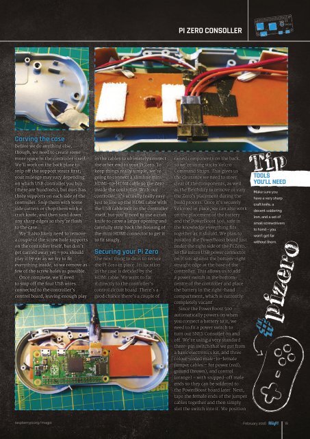
Carving the case<br />
Before we do anything else,<br />
though, we need to create some<br />
more space in the controller itself.<br />
We’ll work on the back plate to<br />
snip off the support struts first;<br />
your mileage may vary depending<br />
on which USB controller you buy<br />
in the cables to ultimately connect<br />
the other end to your Pi Zero. To<br />
keep things really simple, we’re<br />
going to connect a slimline mini<br />
HDMI-to-HDMI cable to the Zero<br />
raised components on the back,<br />
so we’re using sticky Velcro<br />
Command Strips. This gives us<br />
the clearance we need to steer<br />
clear of the components, as well<br />
Tip<br />
TOOLS<br />
YOU’LL NEED<br />
(there are hundreds), but ours has inside the controller. With our as the flexibility to remove or vary<br />
Make sure you<br />
three supports on each side of the controller, it’s actually really easy the Zero’s placement during the<br />
have a very sharp<br />
controller. Snip them with some just to line up the HDMI cable with build process. Once it’s securely<br />
craft knife, a<br />
side cutters or chop them with a the USB cable exit on the controller Velcroed in place, we can also work<br />
decent soldering<br />
craft knife, and then sand down itself, but you’ll need to use a craft on the placement of the battery<br />
iron, and a set of<br />
any sharp edges so they’re flush knife to carve a larger opening and and the PowerBoost 500, safe in<br />
small screwdrivers<br />
to the case.<br />
carefully strip back the housing of the knowledge everything fits<br />
to hand – you<br />
We’ll also likely need to remove the mini HDMI connector to get it together as it should. We plan to<br />
won’t get far<br />
a couple of the screw hole supports to fit snugly.<br />
position the PowerBoost board just<br />
#pizero<br />
without them.<br />
on the controller itself, but don’t<br />
under the right side of the Pi Zero,<br />
get carried away yet – you should Securing your Pi Zero so the micro USB power connector<br />
play it by ear as we try to fit<br />
The next thing to do is to secure on it sits against the bottom-right<br />
everything inside, so we remove as the Pi Zero in place. Its location straight edge at the base of the<br />
few of the screw holes as possible. in the case is decided by the<br />
controller. This allows us to add<br />
Once complete, we’ll need HDMI cable. We want to fix<br />
a power switch in the bottomcentre<br />
of the controller and place<br />
to snip off the four USB wires it directly to the controller’s<br />
connected to the controller’s control circuit board. There’s a the battery in the right-hand<br />
control board, leaving enough play good chance there’s a couple of compartment, which is currently<br />
completely vacant.<br />
Since the PowerBoost 500<br />
automatically powers on when<br />
you connect a battery to it, we<br />
need to fit a power switch to<br />
turn our SNES Consoller on and<br />
raspberrypi.org/magpi February 2016 19<br />
off. We’re using a very standard<br />
three-pin switch that we got from<br />
a basic electronics kit, and three<br />
colour-coded male-to-female<br />
jumper cables – for power (red),<br />
ground (brown), and control<br />
(orange) – with snipped-off male<br />
ends so they can be soldered to<br />
the PowerBoost board later. Next,<br />
tape the female ends of the jumper<br />
cables together and then simply<br />
slot the switch into it. We position