


Create successful ePaper yourself
Turn your PDF publications into a flip-book with our unique Google optimized e-Paper software.
HUNT THE SNARK<br />
Tutorial<br />
MODIFYING THE REMOTE<br />
E<br />
C<br />
B<br />
E<br />
C<br />
B<br />
E<br />
C<br />
B<br />
E<br />
C<br />
B<br />
E<br />
C<br />
B<br />
332<br />
332<br />
332<br />
332<br />
332<br />
332<br />
332<br />
332<br />
332<br />
332<br />
B<br />
C<br />
E<br />
B<br />
C<br />
E<br />
B<br />
C<br />
E<br />
B<br />
C<br />
E<br />
B<br />
C<br />
E<br />
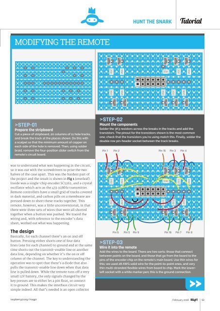
>STEP-01<br />
Prepare the stripboard<br />
Cut a piece of stripboard, 20 columns of 11 hole tracks,<br />
and break the track at the places shown. Do this with<br />
a scalpel so that the minimum amount of copper on<br />
each side of the hole is removed. Then, using solder<br />
braid, remove the four-position slider switch from the<br />
remote’s circuit board.<br />
>STEP-02<br />
Mount the components<br />
Solder the 3K3 resistors across the breaks in the tracks and add the<br />
transistors. The pinout for the transistors shown is the most common<br />
one; check that the transistors you’re using match this. Finally, solder the<br />
double row pin-header socket between the track breaks.<br />
Pin 1 Pin 2 Pin 15 Pin 3 Pin 4<br />
was to understand what was happening in the circuit,<br />
so it was out with the screwdrivers to prise the two<br />
halves of the case apart. This was the hardest part of<br />
the project and the result is shown in Fig 1 (overleaf).<br />
Inside was a single-chip encoder SC5262, and a crystal<br />
oscillator which acts as the 433.92MHz transmitter.<br />
Remote controllers have a small grid of tracks covered<br />
in dark material, and carbon pills on a membrane are<br />
pressed down to short these tracks together. This<br />
remote, however, was a little unconventional, in that<br />
there were three sets of wires that were all shorted<br />
together when a button was pushed. We traced the<br />
wiring and, with reference to the encoder’s data<br />
sheet, worked out what was happening.<br />
E<br />
C<br />
B<br />
332<br />
332<br />
B<br />
C<br />
E<br />
E<br />
C<br />
B<br />
332<br />
332<br />
B<br />
C<br />
E<br />
E<br />
C<br />
B<br />
332<br />
332<br />
B<br />
C<br />
E<br />
E<br />
C<br />
B<br />
332<br />
B<br />
C<br />
E<br />
332<br />
E<br />
C<br />
B<br />
332<br />
B<br />
C<br />
E<br />
332<br />
The design<br />
Basically, for each channel there’s an on and off<br />
button. Pressing either shorts one of four data<br />
lines (one for each channel) to ground and at the same<br />
time shorts out the transmit-enable line or another<br />
data line, depending on whether it’s the on or off<br />
column of the channel. The key to understanding the<br />
operation was to spot that there’s a diode that also<br />
pulls the transmit-enable line down when that data<br />
line is pulled down. While the remote runs off a very<br />
small 12V battery, the only signals changed by the<br />
key presses are to either let a pin float, or connect<br />
it to ground. This makes the interface circuit very<br />
simple indeed. All that’s needed is an open collector<br />
Pin 6 Pin 5 Pin 9<br />
Pin 16 Pin 7 Pin 8<br />
>STEP-03<br />
Wire it into the remote<br />
Add the wires to the board. There are two sorts: those that connect<br />
between points on the board, and those that go from the board to the<br />
pins of the encoder chip on the remote’s main board. Use thin wires for<br />
this; we used 28 AWG solid wire for the point-to-point ones, and very<br />
thin multi-stranded flexible wires from board to chip. Mark the lowerleft<br />
socket with a white marker pen; this is the ground connection.<br />
raspberrypi.org/magpi February 2016 53