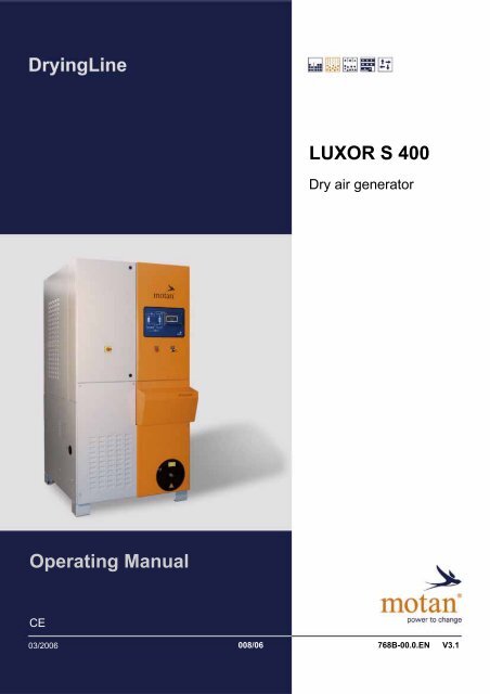
Operating Manual LUXOR S 400
Operating Manual LUXOR S 400
Operating Manual LUXOR S 400
You also want an ePaper? Increase the reach of your titles
YUMPU automatically turns print PDFs into web optimized ePapers that Google loves.
<strong>Operating</strong> <strong>Manual</strong><br />
CE<br />
<strong>LUXOR</strong> S <strong>400</strong><br />
Dry air generator<br />
03/2006 008/06<br />
768B-00.0.EN V3.1
3 Technical specifications<br />
Specifications <strong>LUXOR</strong> S <strong>400</strong><br />
3.3 Specifications<br />
3.3.1 Dimensions of the dry air generator<br />
NOTE<br />
Please observe the minimum clearance around the dry air generator.<br />
Fig. 3.2 – Dimensions and minimum clearances in mm (inch)<br />
[A] Work area<br />
[B] Removal depth, filter cartridge<br />
[C] Passage<br />
[D] Cooler air outlet clearance<br />
[1] Regeneration air outlet<br />
[2] Connection, dry (process) air (to drying hopper)<br />
[3] Connection, return air (from drying hopper)<br />
14 Edition: August 2005
<strong>LUXOR</strong> S <strong>400</strong><br />
5 Structure and function<br />
5.1 Structure of the dry air generator<br />
Fig. 5.1 – Inner view, dry air generator<br />
[A] Rear view<br />
[B] Front view<br />
[1] Dry (process) air (to drying hopper)<br />
[2] Entrance, regeneration air with filter grid<br />
[3] Regeneration air exit<br />
[4] Heat exchanger, regeneration air<br />
[5] Switching valves, drying register<br />
[6] Regeneration air heater<br />
[7] Drying agent cartridge 1<br />
Structure and function 5<br />
Structure of the dry air generator<br />
[8] Switching valves, bottom drying register<br />
[9] Regeneration air blower<br />
[10] Dry (process) air blower<br />
[11] Drying agent cartridge 2<br />
[12] Return air (from drying hopper)<br />
[13] Dry air filter<br />
[14] Regeneration air cooler<br />
[15] Switching valves (regeneration air/cooling air)<br />
Edition: August 2005 25
5 Structure and function<br />
The drying process <strong>LUXOR</strong> S <strong>400</strong><br />
5.2 The drying process<br />
Fig. 5.2 – Function diagram<br />
[1] Dry (process) air (to drying hopper)<br />
[2] Entrance, regeneration air with filter grid<br />
[3] Regeneration air exit<br />
[4] Heat exchanger, regeneration air<br />
[5] Top switching valves<br />
[6] Regeneration air heater<br />
[7] Drying agent cartridge 1<br />
[8] Bottom switching valves<br />
NOTE<br />
Drying register<br />
[9] Dry (process) air blower<br />
[10] Regeneration air blower<br />
[11] Drying agent cartridge 2<br />
[12] Return air (from drying hopper)<br />
[13] Dry air filter<br />
[14] Regeneration air cooler<br />
[15] Switching valves (regeneration air/cooling air)<br />
[16] Dry hopper (not included with equipment supplied)<br />
The two drying agent cartridges [7, 11] with the top and bottom switching valves [5, 8]<br />
are designated the drying register.<br />
26 Edition: August 2005
<strong>LUXOR</strong> S <strong>400</strong><br />
Structure and function 5<br />
The drying process<br />
The dry air generation uses a two cartridge system to continually remove humidity from the hygroscopic<br />
plastic granulate down to a residual humidity of 0.02 % or less.<br />
Both drying agent cartridges [7, 11] compliment each other in their function: While one drying agent<br />
cartridge dries out the returned air, the other drying agent cartridge regenerates.<br />
Drying<br />
The dry (process) air blower [9] pulls in humid return air through the upstream dry air filter [13] from<br />
the drying hopper [16] containing the plastic granulate to be dried . The blower pushes the return air<br />
through the bottom switching valve [8] to the drying agent cartridge 2 [11]. The drying agent (adsorption<br />
agent) within draws out the humidity from the air. The dried air, now called dry (process) air,<br />
passes through the top switching valve [5] back into the drying hopper [16] and remains there for drying.<br />
Regeneration<br />
At the same time, the drying agent cartridge 1 [7] is subject to a regeneration process, until the saturated<br />
drying agent is regenerated. The regeneration air blower [10] pushes air, called regeneration<br />
air, through the regeneration circuit to the regeneration air heater [6]. The regeneration air, which has<br />
been heated to 250 °C (480 °F), flows through the drying agent cartridge 1 [7], thus regenerating the<br />
drying agent by the regeneration air taking up the humidity within the drying agent. Humid regeneration<br />
air is drawn off to the normal air via the regeneration air heat exchanger [4]. At the same time,<br />
the regeneration air blower [10] pulls in normal air from outside. The regeneration air heat exchanger<br />
[4] warms up the normal air, before it enters the regeneration circuit.<br />
Cooling<br />
After regeneration with hot regeneration air, the temperature of the drying agent cartridge 1 [7] is too<br />
high to be able to be used for drying. Therefore, the regeneration circuit must be cooled after regeneration<br />
of the drying agent. The regeneration air heater [6] switches off as soon as drying agent cartridge<br />
1 [7] has reached the "regeneration" reference temperature. Now, the regeneration air/cooling<br />
air circuits [15] short circuit the regeneration circuit, and the connection to normal air is interrupted.<br />
This offers the advantage that no humidity can enter the regeneration circuit from the normal air. The<br />
regeneration air flows in a closed regeneration circuit through the regeneration cooler [14] and cools<br />
the regeneration circuit to the "cooling" reference temperature.<br />
Should the cycle time for drying agent cartridge 2 [11] not yet have been reached, the fan and the<br />
regeneration air blower [10] switch themselves off. Only when the cycle time for drying with drying<br />
agent cartridge 2 [11] has elapsed does the system switch: drying agent cartridge 2 [11] regenerates,<br />
drying agent cartridge 1 [7] dries.<br />
Edition: August 2005 27
<strong>LUXOR</strong> S <strong>400</strong><br />
9.3 Maintenance entrance points<br />
Fig. 9.1 – Maintenance entrance points, overview<br />
[1] Compressed air filter<br />
[2] Dry air filter<br />
[3] Pneumatic cylinder<br />
[4] Air pressure monitor for dry air filter<br />
[5] Filter sieve at regeneration air inlet<br />
Maintenance and repair 9<br />
Maintenance entrance points<br />
[6] Temperature limiter<br />
[7] Air pressure monitor for regeneration air heater<br />
[8] Regeneration air heater<br />
[9] Drying agent cartridges with adsorption material<br />
[10] Temperature sensor<br />
Edition: August 2005 47
<strong>LUXOR</strong> S <strong>400</strong><br />
Every three years<br />
9.5 Maintenance work<br />
9.5.1 Clean the dry air filter<br />
Clean or exchange the dry air filter through the opening in the front panel of the unit.<br />
Maintenance and repair 9<br />
Maintenance work<br />
Component Activity Target value/Meaning Qualification<br />
Adsorption agent (drying<br />
agent cartridges)<br />
� Prepare the dry air generator for maintenance (see “Maintenance and repair“ on Page 46.<br />
� Unscrew the wing nut [1] with the cover [2].<br />
Exchange See Page 54 Specialist<br />
personnel<br />
Temperature sensor Exchange See Page 65 Specialist<br />
personnel<br />
Air pressure monitor for<br />
regeneration air heater<br />
Fig. 9.2 – Remove the filter cartridge<br />
� Unscrew the hexagonal nut [3] and remove the filter cartridge [4] from the housing.<br />
CAUTION!<br />
WARNING!<br />
Exchange Flow monitor, see Page 67 Specialist<br />
personnel<br />
[1] Wing nut<br />
[2] Cover<br />
[3] Hexagonal nut<br />
[4] Filter cartridge<br />
MATERIAL DAMAGE!<br />
On blowing out the dry air filter housing, impurities may be blown into the drying agent.<br />
� Therefore, do not blow out the dry air filter housing with compressed air.<br />
� Vacuum the dry air filter housing.<br />
DANGER TO HEALTH!<br />
Dust is whipped up when the filter cartridge is blown out!<br />
� Wear protective glasses and a dust protection mask.<br />
� Blow out the filter cartridge in an outwards direction using compressed air.<br />
Edition: August 2005 49
9 Maintenance and repair<br />
Maintenance work <strong>LUXOR</strong> S <strong>400</strong><br />
Fig. 9.3 – Cleaning the filter cartridge<br />
� Assemble in reverse order of disassembly.<br />
NOTE<br />
Disposing of the filter cartridge<br />
Dispose of the filter cartridge as special waste in accordance with local regulations.<br />
9.5.2 Checking the air pressure monitor for the regeneration air of the heater<br />
[1] Air pressure monitor<br />
[2] Measuring tube<br />
[3] Heater enclosure<br />
Fig. 9.4 – Checking the air pressure monitor for the regeneration air of the heater<br />
� Prepare the dry air generator for maintenance (see “Maintenance and repair“ on Page 46).<br />
� Remove the back panel of the unit.<br />
� Unscrew the hose [2] on the pressure side of the heater enclosure [3].<br />
50 Edition: August 2005
<strong>LUXOR</strong> S <strong>400</strong><br />
� Switch the dry air generator on.<br />
Maintenance and repair 9<br />
Maintenance work<br />
� The air pressure monitor [1] is working properly, when the alarm lamp illuminates and the message<br />
"Alarm: No Regeneration air flow" appears in the display.<br />
� Screw the measuring tube [2] back on the nipple on the heater enclosure [3].<br />
� The alarm message disappears and the alarm has been canceled.<br />
� Disconnect the dry air generator from the power supply.<br />
� Attach the rear panel of the unit.<br />
NOTE<br />
Replacing the air pressure monitor<br />
For a description of how to replace the air pressure monitor, please refer to Chapter<br />
“Replacing the air pressure monitor for the heater regeneration air“ on Page 67.<br />
9.5.3 Checking the air pressure monitor for the dry air filter<br />
[1] Air pressure monitor<br />
[2] Hose<br />
[3] Dry air filter<br />
Fig. 9.5 – Checking the air pressure monitor for the dry air filter<br />
� Prepare the dry air generator for maintenance (see “Maintenance and repair“ on Page 46).<br />
� Remove the lower front panel.<br />
� Unscrew the hose [2] on the pressure side of the dry air filter [3].<br />
� Switch the dry air generator on.<br />
� Blow lightly in the hose (approx. 5 s).<br />
� The air pressure monitor [1] is working properly, when the alarm lamp illuminates and the message<br />
"Alarm: Clean filter" appears in the display.<br />
Edition: August 2005 51
9 Maintenance and repair<br />
Maintenance work <strong>LUXOR</strong> S <strong>400</strong><br />
� Screw the hose [2] back on the nipple of the dry air filter [3].<br />
� The alarm message disappears and the alarm has been canceled.<br />
� Disconnect the dry air generator from the power supply.<br />
� Replace the lower front panel.<br />
9.5.4 Checking the resistance of the regeneration air heater<br />
� Prepare the dry air generator for maintenance (see “Maintenance and repair“ on Page 46).<br />
� No power supply is required to measure resistance.<br />
� Remove the back panel of the unit.<br />
� Measure the resistance on terminal strip –X13E1.<br />
� The resistance must be about 34 �.<br />
Power Voltage Resistance<br />
9 kW 230/<strong>400</strong> V approx. 34 �<br />
Fig. 9.6 – Measure resistance<br />
52 Edition: August 2005
<strong>LUXOR</strong> S <strong>400</strong><br />
Maintenance and repair 9<br />
Maintenance work<br />
9.5.5 Checking/exchanging the temperature limiter<br />
The temperature limiter is located in the radiator at the bottom end of the regeneration air heater.<br />
The capillary line [4] firmly connected the capillary sensor [1] with the temperature limiter.<br />
Fig. 9.7 – Fixing the temperature limiter, capillary sensor<br />
Removal<br />
� Prepare the dry air generator for maintenance (see “Maintenance and repair“ on Page 46).<br />
� Remove the back panel of the unit.<br />
� Slacken the screw [3] and remove the locking varnish.<br />
� Pull out the capillary sensor on the capillary line [4] and remove with the spring [2].<br />
� Switch the dry air generator on.<br />
� Using the hot air blower (no flames), warm up the capillary sensor [1] until an alarm trigger.<br />
� The temperature limiter must trip, i.e. the regeneration air heater switches off automatically.<br />
The alarm lap illuminates and the message: "Alarm: Regeneration temp. switch tripped out"<br />
appears in the display.<br />
� If no alarm is tripped, the temperature limiter is defective and must be replaced.<br />
� If necessary, unlock the temperature limiter (see “Unlocking temperature limiter“ on Page 68).<br />
If the alarm is still pending after resetting the temperature limiter, then this can have one of many<br />
causes:<br />
� The temperature limiter is defective and must be replaced, or<br />
� The temperature on the capillary sensor is still to high.<br />
� Wait until the capillary sensor has cooled down.<br />
[1] Capillary sensor<br />
[2] Spring<br />
[3] Screw<br />
[4] Capillary line<br />
Edition: August 2005 53
9 Maintenance and repair<br />
Maintenance work <strong>LUXOR</strong> S <strong>400</strong><br />
Installation<br />
� Carry out installation in a logical, reverse order.<br />
� Guide the capillary sensor and spring [2] with the capillary line into the heater. Fix the end of the<br />
spring with the screw [3].<br />
NOTE<br />
Make sure that the capillary line is not bent in any way and is not trapped by the screw.<br />
Connecting the temperature limiter: See “Circuit diagrams“ on Page 95.<br />
� Disconnect the dry air generator from the power supply.<br />
� Attach the rear panel of the unit.<br />
9.5.6 Replacing the adsorption agent (drying agent)<br />
WARNING!<br />
NOTE<br />
NOTE<br />
DANGER TO HEALTH!<br />
The activated adsorption agent generates heat in contact with water.<br />
Burns to the skin and drying out of the skin may occur.<br />
The dust may also cause respiratory problems.<br />
There is a danger of irritation of the eyes.<br />
� Wear protective gloves.<br />
� Wear a respirator.<br />
� Wear safety goggles.<br />
Observe the safety datasheet on the absorption agent (drying agent/molecular sieve)<br />
in “Safety instruction, adsorption agent“ on Page 93 .<br />
Disposal of the adsorption agent<br />
Used adsorption agents may contain impurities. Dispose of used adsorption agents<br />
as special waste in accordance with local regulations.<br />
Fig. 9.8 – Replacing the adsorption agent<br />
[1] Filler opening cover<br />
[2] Insulation<br />
[3] Protective enclosure<br />
[4] Adsorption agent<br />
54 Edition: August 2005
<strong>LUXOR</strong> S <strong>400</strong><br />
Maintenance and repair 9<br />
Maintenance work<br />
� Prepare the dry air generator for maintenance (see “Maintenance and repair“ on Page 46<br />
� “Maintenance and repair“ on Page 46<br />
� Remove the back panel of the unit.<br />
� Open the protective enclosure over the insulation [3].<br />
� Separate the insulation [2] at the joint.<br />
� Remove the screws on the filler opening cover [1] and remove the cover with the gasket.<br />
� Remove the silicone residues on the filler opening, cover and gasket.<br />
� Extract the adsorption agent [4] completely with a vacuum cleaner.<br />
Structure<br />
� Add new adsorption agent (35 kg / 77 lb per drying agent cartridge).<br />
� Check that the gasket is undamaged. Replace a damaged gasket.<br />
� Screw the filler opening cover [1] in place and seal the filler opening with silicone.<br />
� Seal the insulation [2] with aluminum foil.<br />
� Close the protective enclosure over the insulation [3].<br />
� Attach the rear panel of the unit.<br />
9.5.7 Emptying the compressed air filter and/or condensate tank<br />
CAUTION!<br />
FUNCTIONAL ERRORS!<br />
If the level of the condensate tank is above the top mark, then condensate may<br />
ingress into the pressure controller and cause functional errors (setting errors).<br />
� Empty the condensate tank before the condensate reaches the top mark.<br />
[1] Plastic button<br />
Fig. 9.9 – Empty the condensate tank<br />
� Press the plastic button [1] until the condensate tank is empty.<br />
Edition: August 2005 55
9 Maintenance and repair<br />
Repair work <strong>LUXOR</strong> S <strong>400</strong><br />
9.6 Repair work<br />
NOTE<br />
9.6.1 Replacing the top pneumatic cylinder on the drying register<br />
Removal<br />
Special tool<br />
To remove the pneumatic cylinders, you require a special tool which can be obtained<br />
from your local Motan contact:<br />
fork wrench, WAF 32, article number: 4069600.<br />
[1] Silicone collar<br />
[2] T piece (infeed air)<br />
[3] Hose (inflow air)<br />
[4] Cover plates<br />
[5] Pneumatic cylinder<br />
Fig. 9.10 – Disconnect hoses and cover plates<br />
� Prepare the dry air generator for maintenance (see “Additional information for repair work“ on<br />
Page 46).<br />
� Remove the back panel of the unit.<br />
� Label the pneumatic hoses on the pneumatic cylinders [5].<br />
� Disconnect the pneumatic hoses on the pneumatic cylinders [5].<br />
� Disconnect the hose (dry (process) air) [3] and pull it off.<br />
� Slacken the silicone collars [1] on the T piece (dry (process) air) [2] and slide it towards the T piece<br />
(dry (process) air) [2].<br />
� Remove the T piece (dry (process) air) [2].<br />
� Remove the cover plates [4] and the insulation under the cover plates.<br />
Fig. 9.11 – Remove top switching valves<br />
[6] Switching valve, drying register<br />
[7] Wide clip and silicone collar<br />
[8] T piece (regeneration air)<br />
56 Edition: August 2005
<strong>LUXOR</strong> S <strong>400</strong><br />
Maintenance and repair 9<br />
Repair work<br />
� Remove the wide clips [7] and slide the silicone collars towards the T piece (regeneration air) [8].<br />
� Unscrew the eight screws on every switching valve [6] and remove the top switching valves.<br />
CAUTION!<br />
� Move the piston rod to center position.<br />
MATERIAL DAMAGE!<br />
Parts which fall into the drying agent cartridge can cause operational faults.<br />
� Make sure that no parts fall into the drying agent cartridge.<br />
Fig. 9.12 – Removing the pneumatic cylinder<br />
[5] Pneumatic cylinder<br />
[9] Counternut<br />
[10] Valve plunger seal<br />
[11] Stop nut<br />
[12] Contact surface of the piston rod<br />
[13] Locknut<br />
� Slacken the counternut [9]. Using a forked wrench (WAF 8), push against the contact surface of<br />
the piston rod [12].<br />
� Remove the valve rocker seal [10] including the supporting rings and spacer sleeve from the piston<br />
rod.<br />
� Unscrew the stop nut [11]. Using a forked wrench (WAF 8), push against the contact surface of<br />
the piston rod [12].<br />
� Slacken the locknut [13] and unscrew the pneumatic cylinder [5] from the switching valve.<br />
NOTE<br />
To slacken the counternut [9], you can push against the contact surface of the piston<br />
rod [12] with an open-ended wrench (WAF 8).<br />
Edition: August 2005 57
9 Maintenance and repair<br />
Repair work <strong>LUXOR</strong> S <strong>400</strong><br />
Installation<br />
Fig. 9.13 – Installing the pneumatic cylinder<br />
� Screw in the pneumatic cylinder [5] to the stop. Then, turn it back a quarter turn and secure the<br />
pneumatic cylinder by tightening the locknut [13] using the special tool (WAF 32).<br />
� Check that it is still possible to turn the pneumatic cylinder [5].<br />
� It must be possible to turn the pneumatic cylinder.<br />
� Screw on the counternut [11]. Using a forked wrench (WAF 8), push against the contact surface<br />
of the piston rod [12].<br />
Fig. 9.14 – Mounting the valve rocker seal<br />
� Install the valve rocker seal [10] together with the supporting plates and spacer sleeve.<br />
� Tighten the counternut [9]. Using a forked wrench (WAF 8), push against the contact surface of<br />
the piston rod [11].<br />
� Check that the valve rocker seal [10] can still be tilted.<br />
� The valve rocker seal [10] must tilt axially.<br />
� Check the position of the valve rocker seal [10].<br />
� The valve rocker seal [10] must seal at the valve housing in both positions.<br />
� Assemble in reverse order of disassembly.<br />
[5] Pneumatic cylinder<br />
[11] Stop nut<br />
[12] Contact surface of the piston rod<br />
[13] Locknut<br />
[9] Counternut<br />
[10] Valve plunger seal<br />
[11] Stop nut<br />
[12] Contact surface of the piston rod<br />
58 Edition: August 2005
<strong>LUXOR</strong> S <strong>400</strong><br />
9.6.2 Replacing the bottom pneumatic cylinder on the drying register<br />
Removal<br />
Fig. 9.15 – Remove bottom switching valves<br />
Maintenance and repair 9<br />
Repair work<br />
� Prepare the dry air generator for maintenance (see “Additional information for repair work“ on<br />
Page 46).<br />
� Remove the back panel of the unit.<br />
� Label the pneumatic hoses on the pneumatic cylinders [5].<br />
� Slacken the pneumatic hoses on the pneumatic cylinders [5].<br />
� Slacken the hose [7] and pull it in<br />
� Slacken the silicone collar [2] pull the T piece (dry (process) air) [1] down.<br />
� Remove the wide clips [4] and slide the silicone collars towards the T piece (regeneration air) [6].<br />
� Unscrew the eight screws on every switching valve and remove the bottom switching valves.<br />
Fig. 9.16 – Removing the pneumatic cylinder<br />
� Move the piston rod to center position.<br />
[1] T piece (infeed air)<br />
[2] Silicone collar<br />
[3] Switching valve, drying register<br />
[4] Wide clip with silicone collar<br />
[5] Pneumatic cylinder<br />
[6] T piece (regeneration air)<br />
[7] Hose<br />
[5] Pneumatic cylinder<br />
[9] Counternut<br />
[10] Valve plunger seal<br />
[11] Stop nut<br />
[12] Contact surface of the piston rod<br />
[13] Locknut<br />
� Slacken the counternut [9]. Using a forked wrench (WAF 8), push against the contact surface of<br />
the piston rod [12].<br />
� Remove the valve rocker seal [10] including the supporting rings and spacer sleeve from the piston<br />
rod.<br />
Edition: August 2005 59
9 Maintenance and repair<br />
Repair work <strong>LUXOR</strong> S <strong>400</strong><br />
� Unscrew the stop nut [11]. Using a forked wrench (WAF 8), push against the contact surface of<br />
the piston rod [12].<br />
� Slacken the locknut [13] and unscrew the pneumatic cylinder [5] from the switching valve.<br />
NOTE<br />
Installation<br />
To slacken the counternut [9], you can push against the contact surface of the piston<br />
rod [12] with an open-ended wrench (WAF 8).<br />
Fig. 9.17 – Installing the pneumatic cylinder<br />
� Screw in the pneumatic cylinder [5] to the stop. Then, turn it back a quarter turn and secure the<br />
pneumatic cylinder by tightening the locknut [13] using the special tool (WAF 32).<br />
� Check that it is still possible to turn the pneumatic cylinder [5].<br />
� It must be possible to turn the pneumatic cylinder.<br />
� Screw on the counternut [11]. Using a forked wrench (WAF 8), push against the contact surface<br />
of the piston rod [12].<br />
Fig. 9.18 – Mounting the valve rocker seal<br />
[5] Pneumatic cylinder<br />
[11] Stop nut<br />
[12] Contact surface of the piston rod<br />
[13] Locknut<br />
[9] Counternut<br />
[10] Valve plunger seal<br />
[11] Stop nut<br />
[12] Contact surface of the piston rod<br />
� Install the valve rocker seal [10] together with the supporting plates and spacer sleeve.<br />
60 Edition: August 2005
<strong>LUXOR</strong> S <strong>400</strong><br />
Maintenance and repair 9<br />
Repair work<br />
� Tighten the counternut [9]. Using a forked wrench (WAF 8), push against the contact surface of<br />
the piston rod [11].<br />
� Check that the valve rocker seal [10] can still be tilted.<br />
� The valve rocker seal [10] must tilt axially.<br />
� Check the position of the valve rocker seal [10].<br />
� The valve rocker seal [10] must seal at the valve housing in both positions.<br />
� Assemble in reverse order of disassembly.<br />
9.6.3 Replacing the pneumatic cylinder of the regeneration air circuit<br />
Removal<br />
Fig. 9.19 – Removing hoses<br />
� Prepare the dry air generator for maintenance (see “Additional information for repair work“ on<br />
Page 46).<br />
� Remove the lower front panel.<br />
� Label the pneumatic hoses on the pneumatic cylinders [8].<br />
� Slacken the pneumatic hoses on the pneumatic cylinders [8].<br />
� Slacken the hoses [2] and [6] on the regeneration air/cooling air switching valve [1].<br />
� Slacken the large strip clamp and silicone sleeve [3] on the heat exchanger nozzle.<br />
� Slacken the four hoses on the retainer panel and remove the regeneration air/cooling air switching<br />
valve [1].<br />
� Slacken the hose [5] on the regeneration air/cooling air switching valve [7].<br />
� Slacken the wide clips and silicone collars [3] on the regeneration air/cooling air switching<br />
valve [7].<br />
� Remove the regeneration air/cooling air switching valve [7].<br />
[1] Regeneration air/cooling air switching valve (upstream of<br />
regeneration air cooler)<br />
[2] Hose (entry to regeneration air cooler)<br />
[3] Wide clip and silicone collar<br />
[4] Heat exchanger<br />
[5] Hose (exit from regeneration air cooler)<br />
[6] Hose (from drying register)<br />
[7] Regeneration air/cooling air switching valve (upstream of<br />
regeneration air blower)<br />
[8] Pneumatic cylinder<br />
Edition: August 2005 61
9 Maintenance and repair<br />
Repair work <strong>LUXOR</strong> S <strong>400</strong><br />
Installation position of the regeneration air/cooling air switching valves<br />
[A] Hose flange: To regeneration air<br />
blower<br />
[B] Hose flange: From the regeneration<br />
air cooler<br />
[C] Hose flange: Heat exchanger<br />
entry, regeneration air<br />
[7] Regeneration air/cooling air<br />
switching valve upstream of<br />
regeneration air blower<br />
Fig. 9.20 – Installation position of the regeneration air/cooling air switching valve upstream of regeneration air<br />
blower<br />
[A] Hose flange: From the drying register<br />
[B] Hose flange: To the regeneration air cooler<br />
[C] Hose flange: Heat exchanger exit, regeneration air<br />
[1] Regeneration air/cooling air switching valve upstream of<br />
regeneration air cooler<br />
Fig. 9.21 – Installation position of the regeneration air/cooling air switching valve upstream of the regeneration<br />
air cooler (in the diagram, the valve is rotated 90° to the left around the vertical axis)<br />
NOTE<br />
The following descriptions apply for both regeneration air/cooling air switching valves,<br />
shown as an example at the regeneration air/cooling air switching valve upstream of<br />
the regeneration air blower [7].<br />
62 Edition: August 2005
<strong>LUXOR</strong> S <strong>400</strong><br />
Fig. 9.22 – Removing the pneumatic cylinder<br />
Maintenance and repair 9<br />
Repair work<br />
� Dismantle the hose flange [A] and [C] from the switching valves, including the silicone seal.<br />
� Pull out the piston rod completely.<br />
� Unscrew the counternut [13]. Using a forked wrench (WAF 8), push against the contact surface of<br />
the piston rod [10].<br />
� Remove the valve rocker seal [12] including the supporting rings from the piston rod.<br />
� Unscrew the stop nut [11].<br />
NOTE<br />
� Push the piston rod in completely.<br />
� Slacken the locknut [9] using the special tool (WAF 32).<br />
� Unscrew the pneumatic cylinder [8].<br />
Installation<br />
[A] Hose flange: To the regeneration blower or from<br />
the drying register<br />
[B] Hose flange: From/to the regeneration air cooler<br />
[C] Hose flange: Heat exchanger entry/exit, regeneration<br />
air<br />
[7] Regeneration air/cooling air switching valve<br />
upstream of regeneration air blower<br />
[8] Pneumatic cylinder<br />
[9] Locknut<br />
[10] Contact surface of the piston rod<br />
[11] Stop nut<br />
[12] Valve rocker seal with supporting rings<br />
[13] Counternut<br />
To slacken the stop nut [11], you can push against the contact surface of the piston<br />
rod [10] with a forked wrench (WAF 8).<br />
Fig. 9.23 – Installing the pneumatic cylinder<br />
[A] Hose flange: To the regeneration blower or from the<br />
drying register<br />
[B] Hose flange: From/to the regeneration air cooler<br />
[C] Hose flange: Heat exchanger entry/exit, regeneration<br />
air<br />
[7] Regeneration air/cooling air switching valve upstream<br />
of regeneration air blower<br />
[8] Pneumatic cylinder<br />
[9] Locknut<br />
[10] Contact surface of the piston rod<br />
[11] Stop nut<br />
� Screw in the pneumatic cylinder [8] to the stop. Then, turn it back a quarter turn and secure the<br />
pneumatic cylinder by tightening the locknut [9] using the special tool (WAF 32).<br />
Edition: August 2005 63
9 Maintenance and repair<br />
Repair work <strong>LUXOR</strong> S <strong>400</strong><br />
� Check that it is still possible to turn the pneumatic cylinder [8].<br />
� It must be possible to turn the pneumatic cylinder.<br />
� Screw on the stop nut [11].<br />
NOTE<br />
To slacken the stop nut [11], you can push against the contact surface of the piston<br />
rod [10] with a forked wrench (WAF 8).<br />
� Pull out the piston rod completely.<br />
Fig. 9.24 – Mounting the valve rocker seal<br />
� Slide the valve rocker seal [12] with the supporting rings onto the piston rod up to the stop nut [11].<br />
CAUTION!<br />
� Screw on a new counternut [13]. In so doing, push against the contact surface of the piston rod<br />
[10] using a forked wrench (WAF 8) and tighten the counternut.<br />
� It must be possible to turn the valve rocker seal.<br />
[7] Regeneration air/cooling air switching<br />
valve upstream of regeneration air blower<br />
[8] Pneumatic cylinder<br />
[9] Locknut<br />
[10] Contact surface of the piston rod<br />
[11] Stop nut<br />
[12] Valve rocker seal with supporting rings<br />
[13] Counternut<br />
MATERIAL DAMAGE!<br />
Tightening the counternut too much can damage the valve rocker seal.<br />
� Make sure that the valve rocker seal is not squeezed.<br />
Fig. 9.25 – Checking the position of the valve rocker seal<br />
[12] Valve rocker seal with supporting rings<br />
[14] Hose flange<br />
64 Edition: August 2005
<strong>LUXOR</strong> S <strong>400</strong><br />
� Push the piston rod in completely.<br />
� Mount the hose flange [14] with the silicone gasket on the switching valve.<br />
Maintenance and repair 9<br />
Repair work<br />
� Tighten the screws of the hose flange [14] to an extent that it is still possible to move the hose<br />
flange.<br />
� Pull the piston right out so the valve rocker seal [12] is fully forward and sealed as shown in the<br />
diagram.<br />
� Tighten the screws of the hose flange [14 in this position.<br />
� The valve rocker seal [12] must be centrally positioned on the hose flange [14].<br />
NOTE<br />
� Assemble in reverse order of disassembly.<br />
9.6.4 Replacing the temperature sensor<br />
The dry air generator contains two temperature sensors:<br />
� Regeneration air heater temperature sensor<br />
� Monitoring temperature sensor, regeneration air/cooling end (regeneration end/cool end).<br />
NOTE<br />
Removal<br />
The valve rocker seal must contact the retaining panel centrally with the regeneration<br />
air/cooling air switching valve downstream of the regeneration air cooler [1].<br />
The following description for installation/removal is valid for both temperature sensor.<br />
Fig. 9.26 – Regeneration air heater temperature sensor<br />
[1] Temperature sensor<br />
[2] Nozzle<br />
[3] Clamping screw<br />
[4] Pipe<br />
Edition: August 2005 65
9 Maintenance and repair<br />
Repair work <strong>LUXOR</strong> S <strong>400</strong><br />
The temperature probe for monitoring is installed in the T-piece between the two bottom drying register<br />
switching valves:<br />
[1] Temperature sensor<br />
[2] Nozzle<br />
[3] Clamping screw<br />
[4] Pipe (T piece)<br />
Fig. 9.27 – Temperature sensor monitoring of regeneration air/cooling air end<br />
� Prepare the dry air generator for maintenance (see “Additional information for repair work“ on<br />
Page 46).<br />
� Remove the back panel of the unit.<br />
� Slacken the clamping screw [3] and pull the temperature sensor [1] out of the nozzle [2].<br />
Installation<br />
� Guide the temperature sensor [1] in the nozzle [2].<br />
NOTE<br />
CAUTION!<br />
Insert the temperature sensor [1], so that the slit is parallel to the air flow direction and<br />
is approximately in the center of the pipe [4].<br />
MATERIAL DAMAGE!<br />
Tightening the clamping screw too much can damage the temperature sensor.<br />
� Make sure that the temperature sensor is not deformed.<br />
� Using the clamping screw [3], clamp the temperature sensor [1] in this position.<br />
� Attach the rear panel of the unit.<br />
66 Edition: August 2005
<strong>LUXOR</strong> S <strong>400</strong><br />
9.6.5 Replacing the air pressure monitor for the heater regeneration air<br />
[1] Air pressure monitor<br />
[2] Pressure hoses<br />
[3] Cables<br />
[4] Strain relief<br />
Fig. 9.28 – Replacing the air pressure monitor for the heater regeneration air<br />
Maintenance and repair 9<br />
Repair work<br />
� Prepare the dry air generator for maintenance (see “Additional information for repair work“ on<br />
Page 46).<br />
� Remove the back panel of the unit.<br />
� Label the pressure hoses [2] and disconnect them.<br />
� Remove the cover.<br />
� Label the cables [3] and disconnect them.<br />
� Slacken the screws of the strain relief [4].<br />
� Unscrew the compressed air monitor.<br />
� Carry out the installation of the new air pressure monitor in a logical, reverse order.<br />
� At the end carry out a function test (see Kapitel “Checking the air pressure monitor for the regeneration<br />
air of the heater“ on Page 50).<br />
NOTE<br />
You can find additional information on the connection of the air pressure monitor in the<br />
circuit diagram.<br />
Edition: August 2005 67
9 Maintenance and repair<br />
Repair work <strong>LUXOR</strong> S <strong>400</strong><br />
9.6.6 Unlocking temperature limiter<br />
DANGER!<br />
� Push the button [1] in the direction of the arrow.<br />
ELECTRIC SHOCK!<br />
High voltages can cause life-threatening currents in the body and injury from electric<br />
shock.<br />
� Allow only trained and qualified electrical technicians to work on the electrical system.<br />
� Before any electrical work disconnect the unit from the power supply and lock to<br />
prevent unauthorized persons switching it on.<br />
Fig. 9.29 – Unlocking temperature limiter<br />
NOTE<br />
[1] Button<br />
Before unlocking, the temperature limiter must have cooled down.<br />
This can take several minutes, depending on the operating situation.<br />
68 Edition: August 2005
<strong>LUXOR</strong> S <strong>400</strong><br />
9.6.7 Resetting the power switch for motors<br />
DANGER!<br />
NOTE<br />
ELECTRIC SHOCK!<br />
Maintenance and repair 9<br />
Repair work<br />
High voltages can cause life-threatening currents in the body and injury from electric<br />
shock.<br />
� Allow only trained and qualified electrical technicians to work on the electrical system.<br />
� Before any electrical work disconnect the unit from the power supply and lock to<br />
prevent unauthorized persons switching it on.<br />
Before resetting the power switch, determine the cause of why it tripped and correct<br />
the fault.<br />
Fig. 9.30 – Resetting the power switch of the blower motors<br />
Power switch Setting value<br />
Dry (process) air blower 9.5 A<br />
Regeneration air blower 2.4 A<br />
[1] Power switch for the dry (process)<br />
air blower<br />
[2] Power switch for the regeneration<br />
air blower<br />
Edition: August 2005 69
9 Maintenance and repair<br />
Repair work <strong>LUXOR</strong> S <strong>400</strong><br />
9.6.8 Resetting the power switch for regeneration air heating<br />
DANGER!<br />
NOTE<br />
ELECTRIC SHOCK!<br />
High voltages can cause life-threatening currents in the body and injury from electric<br />
shock.<br />
� Allow only trained and qualified electrical technicians to work on the electrical system.<br />
� Before any electrical work disconnect the unit from the power supply and lock to<br />
prevent unauthorized persons switching it on.<br />
Before resetting the power switch, determine the cause of why it tripped and correct<br />
the fault.<br />
Fig. 9.31 – Resetting the regeneration air heater power switch<br />
Power switch Setting value<br />
Regeneration air heater 13 A<br />
[1] Power switch for the regeneration<br />
air blower<br />
70 Edition: August 2005
10 Decommissioning and disposal<br />
Disposal of unit parts <strong>LUXOR</strong> S <strong>400</strong><br />
10.2 Disposal of unit parts<br />
CAUTION!<br />
Dispose of unit parts as follows:<br />
DANGER TO PEOPLE AND THE ENVIRONMENT!<br />
Through incorrect disposal of operating fluids.<br />
Incorrect disposal of operating fluids endangers people and damages the environment.<br />
� Dispose of the unit parts and operating fluids sorted and correctly.<br />
� Follow the manufacturer's directions.<br />
Component Disposal<br />
Drying agent (adsorption agent) � According to instructions<br />
Dry air filter � According to instructions<br />
Hoses � Plastic waste<br />
Insulation � Special waste<br />
Blower � Scrap iron<br />
Cables and electrical parts � Electrical waste<br />
Remaining parts of drier � Scrap iron<br />
Controller � Electronic waste<br />
NOTE<br />
Disposal of drying agents/dry air filters<br />
Used drying agents may contain impurities. Dispose of used drying agents in accordance<br />
with local regulations.<br />
74 Edition: August 2005
<strong>LUXOR</strong> S <strong>400</strong><br />
11 Options<br />
11.1 Dew point display<br />
The dew point display [1] displays the current dew point of the dry (process) air.<br />
Fig. 11.1 – Dew point display on front of unit<br />
NOTE<br />
11.1.1 Dew point display<br />
� In the basic screen of the LOGO controller press the arrow key �.<br />
� The "dew point display" screen appears.<br />
� In the "dew point display" screen press the arrow key �.<br />
� The basic screen of the LOGO controller appears.<br />
[1] Dew point display<br />
Options 11<br />
Dew point display<br />
The dew point display is solely intended for display purposes. No values can be<br />
entered. The displayed value has no influence on the drying sequence.<br />
The display range is between -100 °C and +16 °C (-148 °F and 63 °F).<br />
Fig. 11.2 – Basic screen of the LOGO controller and dew point display<br />
Edition: August 2005 75
11 Options<br />
Dew point display <strong>LUXOR</strong> S <strong>400</strong><br />
11.1.2 Maintenance work<br />
Prepare the dry air generator for maintenance and repair work as described in „Before starting work“<br />
on Page 46.<br />
Fig. 11.3 – Fig. 56: Dew point display sensor<br />
The dew point display does not require any maintenance. To guarantee the accuracy of the display<br />
Motan GmbH recommends replacing the sensor [1] every two years.<br />
11.1.3 Spare parts<br />
[1] Dew point display sensor<br />
[2] PTFE hose<br />
[3] PU tube<br />
Item Unit Designation Article no. Remarks<br />
1 1 Dew point display sensor 4158350<br />
2 rm PTFE hose 4044600<br />
3 rm PU tube 4037050<br />
76 Edition: August 2005
<strong>LUXOR</strong> S <strong>400</strong><br />
11.2 Fine dust filter<br />
Options 11<br />
Fine dust filter<br />
The fine dust filter offers additional process safety for sensitive applications, such as CD or cable production.<br />
The fine dust filter holds any sporadic impurities back, which could, for example, come from<br />
the drying agent.<br />
11.2.1 Connecting the process air hoses<br />
NOTE<br />
11.2.2 Maintenance work<br />
Prepare the dry air generator for maintenance and repair work as described in „Before starting work“<br />
on Page 46.<br />
Annually<br />
Connect the drying hopper with the dry air generator only when you have checked the<br />
rotation direction of the dry (process) air blower or discover that the drying hopper is<br />
empty. See „Transport and setup“ on Page 17.<br />
Fig. 11.4 – Connection to the drying hopper (example)<br />
[1] Dry (process) air<br />
[2] Return air<br />
[3] Fine dust filter<br />
Component Activity Qualification<br />
Fine dust filter Clean, as necessary Operator<br />
Fig. 11.5 – Remove the filter cartridge<br />
[1] Wing nut<br />
[2] Cover<br />
[3] Hexagonal nut<br />
[4] Filter cartridge<br />
Edition: August 2005 77
11 Options<br />
Fine dust filter <strong>LUXOR</strong> S <strong>400</strong><br />
� Unscrew the wing nut [1] with the cover [2].<br />
� Unscrew the hexagonal nut [3] and remove the filter cartridge [4] from the housing.<br />
CAUTION!<br />
WARNING!<br />
� Blow out the filter cartridge in an outwards direction using compressed air.<br />
� Assemble in reverse order of disassembly.<br />
11.2.3 Spare parts<br />
MATERIAL DAMAGE!<br />
When you blow out the fine dust filter housing, impurities maybe blown into other parts<br />
of the dry air generator.<br />
� Therefore, do not blow out the fine dust filter housing with compressed air.<br />
� Vacuum the fine dust filter housing.<br />
DANGER TO HEALTH!<br />
Dust is whipped up when the filter cartridge is blown out!<br />
� Wear protective glasses and a dust protection mask.<br />
Fig. 11.6 – Cleaning the filter cartridge<br />
NOTE<br />
Disposing of the filter cartridge<br />
Dispose of the filter cartridge as special waste in accordance with local regulations.<br />
Item Unit Designation Article no. Remarks<br />
4 1 Filter cartridge 4077570<br />
78 Edition: August 2005
<strong>LUXOR</strong> S <strong>400</strong><br />
11.3 Regeneration air cooler (water)<br />
Options 11<br />
Regeneration air cooler (water)<br />
The regeneration air cooler (water) cools the hot regeneration air to the cooling unit reference<br />
temperature after regeneration.<br />
Fig. 11.7 – Regeneration air cooler (water)<br />
11.3.1 Connect cooling water<br />
Fig. 11.8 – Connect cooling water<br />
A<br />
[A] View from above<br />
[1] Regeneration air cooler<br />
(water)<br />
[2] Stop valve<br />
[1] Cooling water return (arrow down)<br />
[2] Cooling water feed (arrow up)<br />
Edition: August 2005 79
11 Options<br />
Regeneration air cooler (water) <strong>LUXOR</strong> S <strong>400</strong><br />
� Connect a suitable hose (D i = 13mm/0.51") for cooling water feed to the cooling water feed [2].<br />
� Connect a suitable hose to the cooling water outflow [1] to allow the cooling water to flow out.<br />
� Flow volume and maximum permitted cooling water pressure, see „Specifications“ on Page 80.<br />
� Connect the cooling water.<br />
11.3.2 Specifications<br />
Hose connection diameter 13 mm 0.51"<br />
Water flow 0.2–1.0 m 3 /h 0.1–0.6 cfm<br />
Water pressure 0.2–10 bar 3–140 psi<br />
opt. water temperature < 20 °C < 68 °F<br />
Weight approx. 4.5 kg approx. 10 lbs<br />
11.3.3 Spare parts (view from above)<br />
Spare parts list<br />
Item Unit Designation Article no. Remarks<br />
1 1 Cooler 5080350<br />
2 rm Cooling water hose Ø 13x4 mm (Ø 0.51x0.16") 4088100<br />
3 1 Stop valve 4158040<br />
80 Edition: August 2005
<strong>LUXOR</strong> S <strong>400</strong><br />
11.4 Return air cooler<br />
Options 11<br />
Return air cooler<br />
The return air cooler is necessary if you are drying at very high temperatures (above approximately<br />
>120 °C / 250 °F). The lower the return air temperature is, the better the dry air generator can remove<br />
the humidity from this air, i.e. the effectiveness of the drying system increases.<br />
The return air cooler consists of a water cooler [1], a blocking valve [2], the inlet cooling water [3] and<br />
the return line cooling water [4]. The cooling water flows through the inlet [3] into the water cooler [1]<br />
and cools the air which flows by.<br />
Fig. 11.9 – Return air cooler<br />
[1] Water cooler<br />
[2] Stop valve<br />
[3] Cooling water feed (arrow up)<br />
[4] Cooling water return (arrow down)<br />
Edition: August 2005 81
11 Options<br />
Return air cooler <strong>LUXOR</strong> S <strong>400</strong><br />
11.4.1 Connect cooling water<br />
Fig. 11.10 – Connect cooling water<br />
� Connect a suitable hose (D i = 13mm/0.51") for cooling water feed to the cooling water feed [2].<br />
� Connect a suitable hose to the cooling water outflow [1] to allow the cooling water to flow out.<br />
� Flow volume, maximum permissible inflow temperature of the cooling water and maximum permitted<br />
cooling water pressure, see „Specifications“ on Page 83.<br />
� Connect the cooling water.<br />
[1] Water cooler<br />
[2] Stop valve<br />
[3] Cooling water return (arrow down)<br />
[4] Cooling water feed (arrow up)<br />
82 Edition: August 2005
<strong>LUXOR</strong> S <strong>400</strong><br />
11.4.2 Specifications<br />
Fig. 11.11 – Dimensions of return air cooler in mm (inch)<br />
Options 11<br />
Return air cooler<br />
Hose connection diameter 13 mm 0.51“<br />
Water flow 0.1–1.5 m 3 /h 0.06–0.9 cfm<br />
Water pressure 0.2–10 bar 3–140 psi<br />
max. water speed 2.5 m/s 82 ft/s<br />
opt. water temperature < 20 °C < 68 °F<br />
Max. water temperature 30 °C 86 °F<br />
Weight approx. 11 kg approx. 24.25 lb<br />
Edition: August 2005 83
11 Options<br />
Return air cooler <strong>LUXOR</strong> S <strong>400</strong><br />
11.4.3 Spare parts<br />
Spare parts list<br />
Item Unit Designation Article no. Remarks<br />
1 1 Return cooler, heat exchanger insert 1902550<br />
2 1 Stop valve 4158040<br />
3 rm Cooling water hose Ø 13x4 mm (Ø 0.51x0.16“) 4088100<br />
84 Edition: August 2005
<strong>LUXOR</strong> S <strong>400</strong><br />
12 Appendix<br />
12.1 Spare parts<br />
12.1.1 Construction of dry air generator<br />
Spare parts list<br />
Appendix 12<br />
Spare parts<br />
Item Unit Designation Article no. Remarks<br />
1 1 Main switch (EMERGENCY STOP switch) i<br />
2 1 Alarm lights<br />
3 1 Controller logo i<br />
4 1 Operation switch<br />
5 rm Silicone spiral hose, black Ø 102 mm (Ø 4.02“) 4081380<br />
6 rm Silicone hose Ø 3x1.5 mm (Ø 0.12x0.06“) 4067530<br />
7 n.B. Hose clip Ø 90-110 mm (Ø 3.54/4.33“) 1123560<br />
8 n.B. Hose clip Ø 70- 90 mm (Ø 2.76/3.54“) 4012190<br />
9 1 Compressed air filter<br />
1103450<br />
1 Filter element<br />
4158190<br />
10 1 Filter cartridge 4077570<br />
11 rm Silicone spiral hose, red Ø 83 mm (Ø 3.27“) 4038260<br />
i See unit lists on the circuit diagrams<br />
Edition: August 2005 85<br />
i<br />
i
12 Appendix<br />
Spare parts <strong>LUXOR</strong> S <strong>400</strong><br />
Spare parts list<br />
Item Unit Designation Article no. Remarks<br />
12 1 Regeneration air blower <strong>400</strong>V/50Hz 4152460<br />
13 1 Fan motor 24 V DC 4065970<br />
14 4.2 m Aluminum tube 4118480<br />
15 1 Air pressure monitor 4066120<br />
16 3 Silicone sleeve Ø 60 mm (Ø 2.36“) 4067570<br />
17 3 Large strip clamp Ø 64/48 mm (Ø 2.52/1.89“) 4073210<br />
C 1 Pneumatic controller See Page 90<br />
B 2 Regeneration air/cooling air switching valve (triple flange<br />
valve)<br />
See Page 89<br />
86 Edition: August 2005
<strong>LUXOR</strong> S <strong>400</strong><br />
Appendix 12<br />
Spare parts<br />
Spare parts list<br />
Item Unit Designation Article no. Remarks<br />
18 1 Filter screen 4069500<br />
19 Heat exchanger, regeneration air, consisting of:<br />
2.0 m Silicone spiral hose, red Ø 102 mm (Ø 4.02“) 4038270 (6.56 ft)<br />
2.0 m Aluminum hose Ø 63 mm (Ø 2.48“) 4065970 (6.56 ft)<br />
2.0 m Aluminum foil, self adhesive 4068010 (6.56 ft)<br />
20 1 Molecular sieve, replacement kit, including:<br />
2x35 kg Molecular sieve 1422200 (2x77 lb)<br />
2 Gasket for filling spout 4077470<br />
1 Tube of silicone <strong>400</strong>0510<br />
2.0 Aluminum foil, self adhesive 4068010 (6.56 ft)<br />
21 n.B Insulation material 4069290<br />
22 5 Large strip clamp Ø 83/48 mm (Ø 3.27/1.89“) 4088310<br />
23 5 Silicone sleeve Ø 80 mm (Ø 3.15“) 4071250<br />
24 1 Silicone spiral hose, red Ø 83 mm (Ø 3.27“) 4038260<br />
Edition: August 2005 87
12 Appendix<br />
Spare parts <strong>LUXOR</strong> S <strong>400</strong><br />
Spare parts list<br />
Item Unit Designation Article no. Remarks<br />
25 1 Dry (process) air blower <strong>400</strong> V/50 Hz 4151910<br />
26 1 Regeneration air heater compressed air monitor 4065450<br />
27 1 Temperature sensor (regeneration air heater)<br />
i<br />
28 n.B. Aluminum foil, self adhesive 4068010<br />
29 1.0 m Rock wool shell Ø 89/20 mm (Ø 3.5/0.79“) 4080650<br />
30 1 Heating element 9 kW / <strong>400</strong> V 4072190<br />
31 1 Temperature limiter, 300 °C (572 °F)<br />
i<br />
32 1 Temperature sensor (monitoring of regeneration air/cooling<br />
air end)<br />
i<br />
33 1 Seal 4071260<br />
34 3 Silicone sleeve Ø 100 mm (Ø 3.94“) 4077690<br />
A 2 Drying register switching valve (twin-flange valve - air<br />
distributor valve (100/80)<br />
i See unit lists on the circuit diagrams<br />
See Page 90<br />
88 Edition: August 2005
<strong>LUXOR</strong> S <strong>400</strong><br />
12.2 Switching valve, drying register<br />
Appendix 12<br />
Switching valve, drying register<br />
Spare parts list<br />
Item Unit Designation Article no. Remarks<br />
1 1 M8 counternut <strong>400</strong>8<strong>400</strong> ISO 7042<br />
2 2 Viton gasket 4036890<br />
3 1 Valve plunger seal 4077510<br />
4 rm PTFE tube Ø 4x1 mm (Ø 0.16x0.04") 4044600 Calibrated<br />
5 1 Pneumatic cylinder 4077540<br />
6 1 Valve seal NW 100 4077500<br />
7 1 Valve seal NW 75 4070600<br />
Edition: August 2005 89
12 Appendix<br />
Switching valve, regeneration air/cooling air <strong>LUXOR</strong> S <strong>400</strong><br />
12.3 Switching valve, regeneration air/cooling air<br />
Spare parts list<br />
Item Unit Designation Article no. Remarks<br />
1 3 Valve seal 4070600<br />
2 rm PTFE tube Ø 4x1 mm (Ø 0.16x0.04") 4044600 Calibrated<br />
3 1 Pneumatic cylinder 4070040<br />
4 1 Valve plunger seal 4070020<br />
5 1 Lock nut M10 4065980 ISO 7042<br />
90 Edition: August 2005
<strong>LUXOR</strong> S <strong>400</strong><br />
12.4 Pneumatic controller<br />
Appendix 12<br />
Pneumatic controller<br />
Spare parts list<br />
Item Unit Designation Article no. Remarks<br />
1 1 Pressure switch 4088320<br />
2 rm PU tube Ø 4x1 mm (Ø 0.16x0.04") 4037050 Calibrated<br />
3 1 Return valve 4088330<br />
4 2 Solenoid valve 4085770<br />
Edition: August 2005 91
12 Appendix<br />
Pneumatics diagram <strong>LUXOR</strong> S <strong>400</strong><br />
12.5 Pneumatics diagram<br />
Fig. 12.1 – Pneumatics diagram<br />
[1] Compressed air filter<br />
[2] Solenoid valve, regeneration valve/cooling air<br />
[3] Solenoid valve, air distributor<br />
[4] Pressure switch<br />
92 Edition: August 2005
<strong>LUXOR</strong> S <strong>400</strong><br />
12.6 Safety instruction, adsorption agent<br />
(Drying agent/molecular sieve)<br />
Z4-01 Art. no. 1422200 with maintenance and repair<br />
12.6.1 Physical and chemical properties<br />
Shape Spherical, firm<br />
Color Beige<br />
Odor Odorless<br />
State change No melting point to 700 °C<br />
Solubility in water Insoluble (20 °C)<br />
pH value approx. 11 (at 100g/l H2O at 20 °C)<br />
Additional data Noncombustible<br />
Appendix 12<br />
Safety instruction, adsorption agent<br />
12.6.2 Dangerous components<br />
This alkali aluminum silicate does not contain any hazardous substances in the sense of EU directive<br />
88/379/EEC.<br />
Possible hazards<br />
� The activated product generates heat when it comes into contact with water, leading to possible<br />
skin burns.<br />
� The product has an adsorbent effect and can cause drying of skin on long exposure.<br />
� If the max. workplace concentration value (6 mg/m 3 in fine dust) is exceeded, the breathing<br />
passages may be mechanically overloaded.<br />
� Irritation of eyes possible.<br />
12.6.3 Protective equipment<br />
Breathing protection Dust mask in case of insufficient ventilation<br />
Hand protection Protective gloves<br />
Eye protection Protective glasses<br />
Edition: August 2005 93
12 Appendix<br />
Safety instruction, adsorption agent <strong>LUXOR</strong> S <strong>400</strong><br />
12.6.4 First aid<br />
Injury Measure<br />
Eye contact Immediately rinse eyes for at least 15 minutes under running water<br />
with the lid open as far as possible.<br />
Skin contact Wash with water.<br />
Ingestion After ingestion, drink plenty of water.<br />
Respiration Go into fresh air.<br />
Additional data The product is an adsorption agent and generates heat when it<br />
comes into contact with water. The used product may contain dangerous<br />
impurities. Symptomatic treatment according to impurity.<br />
12.6.5 Disposal<br />
Used adsorption agents may contain impurities. Dispose of used adsorption agents as special waste<br />
in accordance with local regulations.<br />
Should you require additional information, you can obtain the necessary information for your Motan<br />
contact.<br />
94 Edition: August 2005
8<br />
7<br />
6<br />
5<br />
4<br />
3<br />
2<br />
1<br />
3/ /PE <strong>400</strong>V 50HZ<br />
Netzspannung<br />
Mains voltage<br />
A<br />
A<br />
14kW<br />
Leistung<br />
Capacity<br />
MOTAN GmbH<br />
35A<br />
Vorsicherung<br />
Back-up fuse<br />
B<br />
Steuerspannung AC<br />
Control voltage AC<br />
B<br />
24V<br />
Steuerspannung DC<br />
Control voltage DC<br />
Luxor S <strong>400</strong><br />
C<br />
C<br />
VARIANTE G<br />
VERSION 2.1<br />
Verdrahtungsfarben<br />
Wire colours<br />
21.10.2004<br />
EKA<br />
Option TP, Drahtfarben, kein Nullleiter<br />
V 1.0<br />
Hauptstrom<br />
Main current<br />
Schwarz<br />
Black<br />
08.04.2005<br />
EKA<br />
Regenierluftk�hler<br />
V 2.0<br />
19.01.2006<br />
EKA<br />
Anschluss -19A3<br />
V 2.1<br />
D<br />
Neutralleiter<br />
Neutral conductor<br />
Hellblau<br />
Light-blue<br />
D<br />
Schutzleiter<br />
Protection-leaders<br />
Gr�n gelb<br />
Green yellow<br />
Steuerspannung AC 230V<br />
Control voltage AC 230V<br />
Rot<br />
Red<br />
E<br />
Steuerspannung DC 24V<br />
Control voltage DC 24V<br />
Blau<br />
Blue<br />
E<br />
Fremdspannung<br />
External voltage<br />
Orange<br />
Orange<br />
F<br />
2<br />
F<br />
Projekt:<br />
2.1<br />
Vers.<br />
T1<br />
T11<br />
=<br />
+<br />
Deckblatt<br />
Cover sheet<br />
Luxor S <strong>400</strong><br />
19.01.2006<br />
Datum<br />
EKA<br />
Bearb.<br />
1<br />
Blatt<br />
Kommission: Zeichng.Nr.:<br />
MOTAN GmbH<br />
Max-Eyth-Weg 42<br />
D-88316 Isny<br />
Gepr.<br />
Gr.:<br />
Standard 768G-90.0.00<br />
REG<br />
4<br />
Urspr. 15.11.2004 Ers. f. Ers. d.<br />
3<br />
Norm<br />
�nderung Datum Name<br />
8<br />
7<br />
6<br />
5<br />
2<br />
1
8<br />
7<br />
6<br />
5<br />
4<br />
3<br />
2<br />
1<br />
Typenbezeichnung<br />
Bauteilbezeichnung<br />
A<br />
Positions<br />
Nummer<br />
A<br />
X01<br />
12Q1<br />
1<br />
2<br />
3RT10 16-1JB41<br />
26K1<br />
X12M1<br />
3<br />
4<br />
MNG<br />
18A1<br />
X12M2<br />
5<br />
6<br />
3RT10 16-1JB41<br />
26K2<br />
12Q2<br />
7<br />
8<br />
3RT10 16-1JB41<br />
X13E1<br />
21K2<br />
9<br />
10<br />
B<br />
B<br />
3RT10 16-1JB41<br />
13Q1<br />
21K1<br />
11<br />
12<br />
925<br />
18Q1<br />
26K3<br />
13<br />
14<br />
3RH11 22-1BB40<br />
758-80.2.05<br />
21S1<br />
21K3<br />
15<br />
16<br />
NR.51120<br />
NR.51120<br />
18A1<br />
NR.51120<br />
27K2<br />
27K1<br />
17<br />
18<br />
60x40<br />
21A1<br />
21A2<br />
19<br />
20<br />
12Q1<br />
X61<br />
X17M1<br />
21<br />
22<br />
C<br />
60x40<br />
C<br />
X17Y2<br />
X24S2<br />
23<br />
24<br />
60x40<br />
27K1<br />
21K3<br />
X24S3<br />
X24S4<br />
25<br />
26<br />
970<br />
60x40<br />
X61<br />
21A2<br />
21A1<br />
26K3<br />
21K1 18Q1<br />
21K2 13Q1<br />
26K2 12Q2<br />
26K1<br />
X26Y1<br />
X26Y2<br />
27<br />
28<br />
27K2<br />
60x40<br />
X40<br />
29<br />
X13E1<br />
X12M1<br />
21S1<br />
X01<br />
X12M2<br />
D<br />
X17M1<br />
X17Y2 X24S2<br />
X24S3 X24S4<br />
X26Y1 X26Y2<br />
X40<br />
D<br />
60x60<br />
E<br />
E<br />
F<br />
11<br />
F 2a<br />
Projekt:<br />
2.1<br />
Vers.<br />
T1<br />
T11<br />
=<br />
+<br />
Montageplatte<br />
mounting plate<br />
Luxor S <strong>400</strong><br />
19.01.2006<br />
Datum<br />
EKA<br />
Bearb.<br />
5<br />
Blatt<br />
Kommission: Zeichng.Nr.:<br />
MOTAN GmbH<br />
Max-Eyth-Weg 42<br />
D-88316 Isny<br />
Gepr.<br />
Gr.:<br />
Standard 768G-90.0.00<br />
EKA<br />
4<br />
Urspr. 15.11.2004 Ers. f. Ers. d.<br />
3<br />
Norm<br />
�nderung Datum Name<br />
8<br />
7<br />
6<br />
5<br />
2<br />
1
8<br />
7<br />
6<br />
5<br />
4<br />
3<br />
2<br />
1<br />
1L1/12.1<br />
1L2/12.1<br />
1L3/12.1<br />
A<br />
A<br />
3<br />
2<br />
1<br />
W11Q1.2<br />
PVC Steuerleitung<br />
B<br />
housing frame<br />
Geh„use rahmen<br />
1,5m<br />
4x6 mmý<br />
Panel<br />
Schrank<br />
Porch Door right<br />
Vorbau T�re rechts<br />
Door left<br />
T�re links<br />
Door left<br />
T�re links<br />
mounting plate<br />
Montageplatte<br />
B<br />
T3<br />
T2<br />
T1<br />
L3<br />
L2<br />
L1<br />
+T16<br />
-11Q1<br />
C<br />
PE<br />
PE<br />
PE<br />
PE<br />
PE<br />
C<br />
PE<br />
2PE<br />
2PE<br />
1PE<br />
1PE<br />
-X01<br />
PE<br />
-X01<br />
3<br />
2<br />
1<br />
W11Q1.1<br />
PVC Steuerleitung<br />
6 mmý<br />
GNYE<br />
H07V-K<br />
6 mmý<br />
GNYE<br />
H07V-K<br />
6 mmý<br />
GNYE<br />
H07V-K<br />
1,5m<br />
4x6 mmý<br />
W11Q1.2<br />
PVC<br />
Steuerleitung<br />
W11Q1.1<br />
PVC<br />
Steuerleitung<br />
4x6mmý<br />
4x6mmý<br />
D<br />
D<br />
PE<br />
3<br />
2<br />
-X01 1<br />
GNYE<br />
3<br />
2<br />
1<br />
WT1<br />
PVC Steuerleitung<br />
4x6mmý<br />
6mmý GNYE<br />
+TRO<br />
+T13<br />
+T17<br />
+T16<br />
+T16<br />
PE<br />
L3<br />
L2<br />
L1<br />
Ï<br />
Ï<br />
Ï<br />
Ï<br />
Ï<br />
E<br />
Einspeisung<br />
power supply<br />
E<br />
Potentialausgleich<br />
equipotential bonding<br />
MAX VORSICHERUNG 35A<br />
max back-up fuse 35A<br />
F<br />
12<br />
F 5<br />
Projekt:<br />
2.1<br />
Vers.<br />
T1<br />
T11<br />
=<br />
+<br />
Einspeisung<br />
power supply<br />
Luxor S <strong>400</strong><br />
19.01.2006<br />
Datum<br />
EKA<br />
Bearb.<br />
11<br />
Blatt<br />
Kommission: Zeichng.Nr.:<br />
MOTAN GmbH<br />
Max-Eyth-Weg 42<br />
D-88316 Isny<br />
Gepr.<br />
Gr.:<br />
Standard 768G-90.0.00<br />
REG<br />
4<br />
Urspr. 15.11.2004 Ers. f. Ers. d.<br />
3<br />
Norm<br />
�nderung Datum Name<br />
8<br />
7<br />
6<br />
5<br />
2<br />
1
8<br />
7<br />
6<br />
5<br />
4<br />
3<br />
2<br />
1<br />
1L1/13.1<br />
1L2/13.1<br />
1L3/13.1<br />
11.8/1L1<br />
11.8/1L2<br />
11.8/1L3<br />
A<br />
16mmý 3PH Sammelschienen 3RV19 15-1CB<br />
A<br />
5<br />
3<br />
1<br />
21<br />
5<br />
3<br />
1<br />
-12Q2<br />
2,2-3,2A<br />
(2,4A)<br />
22<br />
14<br />
-12Q1<br />
7-10A<br />
(9,5A)<br />
6<br />
4<br />
2<br />
24.4 13<br />
6<br />
4<br />
2<br />
1,5mmý<br />
BK<br />
H07V-K<br />
B<br />
1,5mmý<br />
BK<br />
H07V-K<br />
B<br />
5<br />
3<br />
1<br />
5<br />
3<br />
1<br />
6<br />
4<br />
2<br />
-26K2<br />
26.3<br />
6<br />
4<br />
2<br />
-26K1<br />
26.2<br />
1,5mmý<br />
BK<br />
H07V-K<br />
1,5mmý<br />
BK<br />
H07V-K<br />
C<br />
C<br />
PE<br />
PE<br />
4PE<br />
3<br />
2<br />
-X12M2 1<br />
4PE<br />
3<br />
2<br />
-X12M1 1<br />
D<br />
GNYE<br />
GY<br />
BK<br />
BN<br />
W12M2<br />
GNYE<br />
GY<br />
BK<br />
BN<br />
W12M1<br />
D<br />
Silikonleitung<br />
1,6m<br />
4x2,5mmý<br />
Silikonleitung<br />
2m<br />
4x2,5mmý<br />
=T1<br />
+TRO<br />
U V W<br />
U V W<br />
M<br />
3 ~<br />
M<br />
3 ~<br />
PE<br />
-12M2<br />
0,85kW<br />
4,2/2,4A<br />
200-240/345-415V 50Hz<br />
PE<br />
-12M1<br />
4kW<br />
16,4/9,5A<br />
200-240/345-415V 50Hz<br />
E<br />
0,95kW<br />
4/2,3A<br />
220-275/380-480V 60Hz<br />
4,6kW<br />
16,4/9,5A<br />
220-275/380-480V 60Hz<br />
E<br />
2BH1500-7AH06<br />
2BH1640-7GH36<br />
Regenerierluft<br />
regenerated air<br />
Trockenluft<br />
dry air<br />
F<br />
13<br />
F 11<br />
Projekt:<br />
2.1<br />
Vers.<br />
T1<br />
T11<br />
=<br />
+<br />
Leistung Gebl„se<br />
capacity blower<br />
Luxor S <strong>400</strong><br />
19.01.2006<br />
Datum<br />
EKA<br />
Bearb.<br />
12<br />
Blatt<br />
Kommission: Zeichng.Nr.:<br />
MOTAN GmbH<br />
Max-Eyth-Weg 42<br />
D-88316 Isny<br />
Gepr.<br />
Gr.:<br />
Standard 768G-90.0.00<br />
REG<br />
4<br />
Urspr. 15.11.2004 Ers. f. Ers. d.<br />
3<br />
Norm<br />
�nderung Datum Name<br />
8<br />
7<br />
6<br />
5<br />
2<br />
1
8<br />
7<br />
6<br />
5<br />
4<br />
3<br />
2<br />
1<br />
1L1/18.1<br />
1L2/18.1<br />
12.8/1L1<br />
12.8/1L2<br />
12.8/1L3<br />
A<br />
16mmý 3PH Sammelschienen 3RV19 15-1CB<br />
16mmý 3PH Sammelschienen 3RV19 15-1CB<br />
A<br />
5<br />
3<br />
1<br />
-13Q1<br />
11-16A<br />
(13A)<br />
6<br />
4<br />
2<br />
2,5mmý<br />
BK<br />
H07V-K<br />
5<br />
3<br />
1<br />
B<br />
B<br />
6<br />
4<br />
2<br />
-21K2<br />
21.7<br />
2,5mmý<br />
BK<br />
H07V-K<br />
5<br />
3<br />
1<br />
6<br />
4<br />
2<br />
-21K1<br />
21.6<br />
C<br />
2,5mmý<br />
BK<br />
H07V-K<br />
C<br />
PE<br />
4PE<br />
3<br />
2<br />
-X13E1 1<br />
D<br />
GNYE<br />
GY<br />
BK<br />
BN<br />
W13E1<br />
D<br />
Silikonleitung<br />
1,5m<br />
4x2,5mmý<br />
PE<br />
W1<br />
V1<br />
U1<br />
=T1<br />
+TRO<br />
-13E1<br />
9kW<br />
13A<br />
<strong>400</strong>V<br />
E<br />
E<br />
regenerieren<br />
to regenerate<br />
F<br />
17<br />
F 12<br />
Projekt:<br />
2.1<br />
Vers.<br />
T1<br />
T11<br />
=<br />
+<br />
Leistung Heizung<br />
capacity heater<br />
Luxor S <strong>400</strong><br />
19.01.2006<br />
Datum<br />
EKA<br />
Bearb.<br />
13<br />
Blatt<br />
Kommission: Zeichng.Nr.:<br />
MOTAN GmbH<br />
Max-Eyth-Weg 42<br />
D-88316 Isny<br />
Gepr.<br />
Gr.:<br />
Standard 768G-90.0.00<br />
REG<br />
4<br />
Urspr. 15.11.2004 Ers. f. Ers. d.<br />
3<br />
Norm<br />
�nderung Datum Name<br />
8<br />
7<br />
6<br />
5<br />
2<br />
1
8<br />
7<br />
6<br />
5<br />
4<br />
3<br />
2<br />
1<br />
/25.3<br />
L+<br />
/27.2<br />
M<br />
A<br />
A<br />
-X60 7<br />
-X61 7<br />
0,75 mmý<br />
DBU<br />
H05V-K<br />
0,75 mmý<br />
DBU<br />
H05V-K<br />
/26.5<br />
M7<br />
B<br />
11<br />
B<br />
-27K2<br />
27.5<br />
13<br />
14<br />
12<br />
14<br />
-26K1<br />
26.2<br />
0,75 mmý<br />
BU H05V-K<br />
21<br />
-26K3<br />
26.4<br />
C<br />
22<br />
C<br />
PE<br />
PE<br />
0,75 mmý<br />
DBU<br />
H05V-K<br />
0,75 mmý<br />
DBU<br />
H05V-K<br />
PE<br />
2<br />
-X17Y2 1<br />
PE<br />
2<br />
-X17M1 1<br />
PE<br />
2<br />
-X17Y1 1<br />
D<br />
GNYE<br />
2<br />
1<br />
W17Y2<br />
0,75 mmý<br />
GNYE<br />
3m<br />
H05V-K<br />
2<br />
1<br />
GNYE<br />
2<br />
1<br />
W17Y1<br />
D<br />
PVC Steuerleitung<br />
5m<br />
3x0,75mmý<br />
W17M1<br />
LZ126<br />
3m<br />
2xAWG 18<br />
PVC Steuerleitung<br />
2m<br />
3x0,75mmý<br />
=T1<br />
+TRO<br />
PE<br />
1<br />
PE<br />
+ -<br />
PE<br />
1<br />
* Option<br />
*<br />
-17Y1<br />
24VDC<br />
5W<br />
*<br />
2<br />
-17Y2<br />
24VDC<br />
5W<br />
M<br />
-17M1<br />
9,5W<br />
2<br />
E<br />
K�hler R�ckluft<br />
cooling return air<br />
K�hler Regenerierluft<br />
cooling regenerated air<br />
K�hler Regenerierluft<br />
cooling regenerated air<br />
E<br />
Wasserk�hler<br />
water cooler<br />
Wasserk�hler<br />
water cooler<br />
F<br />
18<br />
F 13<br />
Projekt:<br />
2.1<br />
Vers.<br />
T1<br />
T11<br />
=<br />
+<br />
K�hler R�ckluft<br />
cooling return air<br />
Luxor S <strong>400</strong><br />
19.01.2006<br />
Datum<br />
EKA<br />
Bearb.<br />
17<br />
Blatt<br />
Kommission: Zeichng.Nr.:<br />
MOTAN GmbH<br />
Max-Eyth-Weg 42<br />
D-88316 Isny<br />
Gepr.<br />
Gr.:<br />
Standard 768G-90.0.00<br />
REG<br />
4<br />
Urspr. 15.11.2004 Ers. f. Ers. d.<br />
3<br />
Norm<br />
�nderung Datum Name<br />
8<br />
7<br />
6<br />
5<br />
2<br />
1
8<br />
7<br />
6<br />
5<br />
4<br />
3<br />
2<br />
1<br />
13.8/1L1<br />
13.8/1L2<br />
A<br />
5<br />
3<br />
1<br />
A<br />
-18Q1<br />
0,45-0,63A<br />
(0,5A)<br />
6<br />
4<br />
2<br />
0,75 mmý<br />
RD<br />
H05V-K<br />
B<br />
B<br />
C<br />
A<br />
-18A1<br />
<strong>400</strong>V 0,5A<br />
24VDC 3,5A<br />
PE<br />
+<br />
-<br />
1,5mmý<br />
DBU<br />
H07V-K<br />
C<br />
C<br />
/19.1<br />
L+<br />
-X61 1<br />
/19.1<br />
M<br />
-X60 1<br />
D<br />
D<br />
*<br />
* When removing this<br />
PE Connection on<br />
Isolation monitoring<br />
1,5mmý<br />
GNYE<br />
H07V-K<br />
1,5mmý<br />
GNYE<br />
H07V-K<br />
will be Nessesary<br />
* Bei Entfernung dieser<br />
PE Verbindung wird<br />
eine Isolations�berwachung<br />
nach VDE 0100 erforderlich<br />
-X12M2 4PE<br />
-X60 1PE<br />
E<br />
E<br />
PE<br />
PE<br />
Netzger„t<br />
power supply unit<br />
F<br />
19<br />
F 17<br />
Projekt:<br />
2.1<br />
Vers.<br />
T1<br />
T11<br />
=<br />
+<br />
Steuerspannung 24V DC<br />
control voltage 24V DC<br />
Luxor S <strong>400</strong><br />
19.01.2006<br />
Datum<br />
EKA<br />
Bearb.<br />
18<br />
Blatt<br />
Kommission: Zeichng.Nr.:<br />
MOTAN GmbH<br />
Max-Eyth-Weg 42<br />
D-88316 Isny<br />
Gepr.<br />
Gr.:<br />
Standard 768G-90.0.00<br />
REG<br />
4<br />
Urspr. 15.11.2004 Ers. f. Ers. d.<br />
3<br />
Norm<br />
�nderung Datum Name<br />
8<br />
7<br />
6<br />
5<br />
2<br />
1
8<br />
7<br />
6<br />
5<br />
4<br />
3<br />
2<br />
1<br />
/21.1<br />
L+<br />
18.7/L+<br />
/21.1<br />
M<br />
18.7/M<br />
A<br />
4<br />
-X61<br />
4<br />
-X60<br />
3<br />
-X61<br />
3<br />
-X60<br />
2<br />
-X61<br />
2<br />
-X60<br />
A<br />
23<br />
22<br />
W19A1<br />
PVC Steuerleitung<br />
3<br />
4<br />
W19A1<br />
PVC Steuerleitung<br />
1<br />
2<br />
W19A1<br />
PVC Steuerleitung<br />
25x0,75<br />
25x0,75mmý<br />
3m<br />
25x0,75mmý<br />
B<br />
B<br />
L+<br />
/32.3<br />
M<br />
/32.3<br />
+T17<br />
-19A3<br />
23.3<br />
32.3<br />
L+<br />
/31.3<br />
M<br />
/31.3<br />
L+<br />
/30.3<br />
M<br />
/30.3<br />
AM2<br />
LOGO Erweiterungsmodul<br />
+T17<br />
-19A2<br />
24.7<br />
25.2<br />
26.7<br />
27.2<br />
27.4<br />
27.6<br />
31.3<br />
12/24RC<br />
LOGO Erweiterungsmodul<br />
+T17<br />
-19A1<br />
24.1<br />
24.2<br />
24.3<br />
24.3<br />
24.4<br />
24.5<br />
24.6<br />
24.7<br />
26.2<br />
26.3<br />
26.4<br />
26.5<br />
30.3<br />
C<br />
12/24RC<br />
C<br />
LOGO<br />
Q1<br />
/<br />
/31.5<br />
Q1<br />
/<br />
/30.5<br />
Q2<br />
/<br />
/31.5<br />
Q2<br />
/<br />
/30.5<br />
Q3<br />
/<br />
/31.5<br />
Q3<br />
/<br />
/30.5<br />
Q4<br />
/<br />
/31.5<br />
Q4<br />
/<br />
/30.5<br />
D<br />
D<br />
E<br />
E<br />
* Option Taupunkt<br />
* Option dew-point<br />
F<br />
21<br />
F 18<br />
Projekt:<br />
2.1<br />
Vers.<br />
T1<br />
T11<br />
=<br />
+<br />
24V DC E/A Module<br />
24V DC E/A module<br />
Luxor S <strong>400</strong><br />
19.01.2006<br />
Datum<br />
EKA<br />
Bearb.<br />
19<br />
Blatt<br />
Kommission: Zeichng.Nr.:<br />
MOTAN GmbH<br />
Max-Eyth-Weg 42<br />
D-88316 Isny<br />
Gepr.<br />
Gr.:<br />
Standard 768G-90.0.00<br />
REG<br />
4<br />
Urspr. 15.11.2004 Ers. f. Ers. d.<br />
3<br />
Norm<br />
�nderung Datum Name<br />
8<br />
7<br />
6<br />
5<br />
2<br />
1
8<br />
7<br />
6<br />
5<br />
4<br />
3<br />
2<br />
1<br />
/24.1<br />
L+<br />
19.8/L+<br />
/27.1<br />
M<br />
19.8/M<br />
A<br />
A<br />
PE<br />
-X60 5<br />
-X61 4 -X60 4<br />
-X13E1 4PE<br />
0,75 mmý<br />
DBU<br />
H05V-K<br />
0,75 mmý<br />
DBU<br />
H05V-K<br />
0,75 mmý<br />
GNYE<br />
H05V-K<br />
B<br />
B<br />
1<br />
3<br />
-21A2<br />
1<br />
3<br />
-21A1<br />
PE<br />
1<br />
-21S1<br />
TB<br />
15 13<br />
24 22<br />
15 13<br />
4<br />
2<br />
13<br />
Freigabe Heizung<br />
enable, clearance heater<br />
11<br />
10<br />
11<br />
10<br />
14<br />
-26K3<br />
26.4<br />
0,75 mmý<br />
DBU<br />
H05V-K<br />
.5 17<br />
0,75 mmý<br />
DBU<br />
H05V-K<br />
24.8 20<br />
24.6 17<br />
C<br />
Grenzwert regenerieren<br />
threshold to regenerate<br />
C<br />
17<br />
Grenzwert<br />
Heizende K�hlende<br />
threshold<br />
heating end Chilling<br />
13<br />
15<br />
Freigabe Heizung<br />
enable, clearance heater<br />
43<br />
-21A2<br />
.4<br />
44<br />
-26K3<br />
26.4<br />
0,75 mmý<br />
DBU<br />
H05V-K<br />
13<br />
BU<br />
RD<br />
W21B2<br />
BU<br />
RD<br />
W21B1<br />
14<br />
-21K2<br />
.7<br />
KE9L-FE/KO 2x0,25<br />
KE9L-FE/KO 2x0,25<br />
D<br />
D<br />
0,75 mmý<br />
DBU<br />
H05V-K<br />
0,75 mmý<br />
DBU<br />
H05V-K<br />
A1<br />
A1<br />
A1<br />
-21K3<br />
PE<br />
PE<br />
A2<br />
A2<br />
-21K2<br />
24 V DCV<br />
A2<br />
-21K1<br />
24 V DCV<br />
/26.1<br />
M5<br />
-<br />
+<br />
-<br />
+<br />
=T1<br />
+TRO<br />
-21B2<br />
-21B1<br />
E<br />
Temperaturbegr.<br />
Regenerieren<br />
safety temperature<br />
switch to regenerate<br />
Sicherheitssch�tz<br />
safety contactor<br />
Heizungsch�tz<br />
heating contactor<br />
E<br />
Temperatur Regenerieren<br />
Temperature to regenerate<br />
Grenzwert heizende/k�hlende<br />
threshold heating end/chilling<br />
NR.51120<br />
14<br />
12 11 24.5<br />
3RT10 16-1JB41<br />
1 2 13.3<br />
3 4 13.3<br />
5 6 13.3<br />
13 14 .6<br />
3RT10 16-1JB41<br />
1 2 13.3<br />
3 4 13.3<br />
5 6 13.3<br />
13 14<br />
F<br />
23<br />
F 19<br />
Projekt:<br />
2.1<br />
Vers.<br />
T1<br />
T11<br />
=<br />
+<br />
Temperatursteuerung<br />
temperature controller<br />
Luxor S <strong>400</strong><br />
19.01.2006<br />
Datum<br />
EKA<br />
Bearb.<br />
21<br />
Blatt<br />
Kommission: Zeichng.Nr.:<br />
MOTAN GmbH<br />
Max-Eyth-Weg 42<br />
D-88316 Isny<br />
Gepr.<br />
Gr.:<br />
Standard 768G-90.0.00<br />
REG<br />
4<br />
Urspr. 15.11.2004 Ers. f. Ers. d.<br />
3<br />
Norm<br />
�nderung Datum Name<br />
8<br />
7<br />
6<br />
5<br />
2<br />
1
8<br />
7<br />
6<br />
5<br />
4<br />
3<br />
2<br />
1<br />
A<br />
A<br />
+TRO<br />
-23B1<br />
B<br />
B<br />
Taupunktsensor<br />
dew-point Sensor<br />
3<br />
1<br />
2<br />
-X23B1 4<br />
C<br />
BU<br />
BN<br />
WH<br />
BK<br />
W23B1<br />
SENSOR<br />
5m 4x0,25 mmý<br />
C<br />
M<br />
L+<br />
M1<br />
I1<br />
M<br />
/32.5<br />
L+<br />
/32.5<br />
I1/U1-<br />
/32.4<br />
I1+<br />
/32.4<br />
D<br />
D<br />
+T17<br />
-19A3<br />
19.7<br />
*Option Taupunkt<br />
E<br />
*Option dew-point<br />
E<br />
F<br />
24<br />
F 21<br />
Projekt:<br />
2.1<br />
Vers.<br />
T1<br />
T11<br />
=<br />
+<br />
Taupunktanzeige<br />
dew point display<br />
Luxor S <strong>400</strong><br />
19.01.2006<br />
Datum<br />
EKA<br />
Bearb.<br />
23<br />
Blatt<br />
Kommission: Zeichng.Nr.:<br />
MOTAN GmbH<br />
Max-Eyth-Weg 42<br />
D-88316 Isny<br />
Gepr.<br />
Gr.:<br />
Standard 768G-90.0.00<br />
REG<br />
4<br />
Urspr. 15.11.2004 Ers. f. Ers. d.<br />
3<br />
Norm<br />
�nderung Datum Name<br />
8<br />
7<br />
6<br />
5<br />
2<br />
1
8<br />
7<br />
6<br />
5<br />
4<br />
3<br />
2<br />
1<br />
/25.1<br />
L+<br />
21.8/L+<br />
3<br />
2<br />
-X61 5<br />
A<br />
W19A1<br />
PVC Steuerleitung<br />
A<br />
-X24S4 1<br />
W24S4<br />
PVC Steuerleitung O<br />
W24S3<br />
PVC Steuerleitung O<br />
-X24S3 1<br />
W24S2<br />
PVC Steuerleitung O<br />
-X24S2 1<br />
20<br />
25x0,75mmý<br />
1<br />
1,5m<br />
2x0,75<br />
1,5m<br />
2x0,75<br />
1<br />
1,5m<br />
2x0,75<br />
1<br />
1<br />
3<br />
+EX<br />
3<br />
+EX<br />
P<br />
-24S4<br />
P<br />
-24S3<br />
P<br />
-24S2<br />
2<br />
0<br />
1<br />
2<br />
2<br />
1<br />
0,75 mmý<br />
DBU<br />
H05V-K<br />
2<br />
1<br />
33<br />
13<br />
34<br />
14<br />
+T17<br />
-24S1<br />
B<br />
2<br />
W24S4<br />
PVC Steuerleitung O<br />
W24S3<br />
PVC Steuerleitung O<br />
2<br />
W24S2<br />
PVC Steuerleitung O<br />
2<br />
B<br />
2x0,75mmý<br />
2x0,75mmý<br />
2x0,75mmý<br />
-X24S4 2<br />
-X24S3 2<br />
-X24S2 2<br />
0,75 mmý<br />
DBU<br />
H05V-K<br />
20<br />
-21A1<br />
21.3<br />
17<br />
-21A1<br />
21.2<br />
11<br />
-21K3<br />
21.8<br />
13<br />
24 22<br />
13<br />
15<br />
14<br />
12<br />
14<br />
-12Q1<br />
12.2<br />
C<br />
C<br />
W19A1<br />
PVC Steuerleitung<br />
11<br />
10<br />
9<br />
8<br />
7<br />
6<br />
5<br />
25x0,75mmý<br />
D<br />
D<br />
I1<br />
I8<br />
I7<br />
I6<br />
I5<br />
I4<br />
I3<br />
I2<br />
I1<br />
E9<br />
/31.4<br />
TS1-T101<br />
E8<br />
/30.4<br />
PS02T101<br />
E7<br />
/30.4<br />
TS1+T101<br />
E6<br />
/30.4<br />
TZ01T101<br />
E5<br />
/30.4<br />
PDS1T101<br />
E4<br />
/30.4<br />
EZ01T101<br />
E3<br />
/30.4<br />
PSD1T101<br />
E2<br />
/30.4<br />
TSD1T101<br />
E1<br />
/30.3<br />
HSD1T101<br />
E<br />
+T17<br />
-19A2<br />
+T17<br />
-19A1<br />
+T17<br />
-19A1<br />
+T17<br />
-19A1<br />
+T17<br />
-19A1<br />
+T17<br />
-19A1<br />
+T17<br />
-19A1<br />
+T17<br />
-19A1<br />
+T17<br />
-19A1<br />
E<br />
19.4<br />
19.2<br />
19.2<br />
19.2<br />
19.2<br />
19.2<br />
19.2<br />
19.2<br />
19.2<br />
Grenzwert k�hlende<br />
regenerieraustritt<br />
threshols chillling<br />
regenerate outlet<br />
Druckluftversorgung<br />
Compressed<br />
air-care<br />
Grenzwert<br />
Si.-Thermostat<br />
Regnerierluft<br />
Sec. thermostat<br />
regenerated air<br />
Druckschalter<br />
Filter Trockenluft<br />
Motorschutz<br />
Gebl„se Trockenluft<br />
Druckschalter<br />
Str”mung regenerieren.<br />
Schaltuhrbetrieb<br />
timer operation<br />
Handbetrieb<br />
manual operation<br />
Heizende Regenerieraustritt<br />
Limit<br />
heating regenerate leaves<br />
pressure fiilter<br />
dry air<br />
motor protection<br />
blower dry air<br />
Pressure switch<br />
flow to regenerate.<br />
F<br />
25<br />
F 23<br />
Projekt:<br />
2.1<br />
Vers.<br />
T1<br />
T11<br />
=<br />
+<br />
Digitaleing„nge 24V DC<br />
digital input 24V DC<br />
Luxor S <strong>400</strong><br />
19.01.2006<br />
Datum<br />
EKA<br />
Bearb.<br />
24<br />
Blatt<br />
Kommission: Zeichng.Nr.:<br />
MOTAN GmbH<br />
Max-Eyth-Weg 42<br />
D-88316 Isny<br />
Gepr.<br />
Gr.:<br />
Standard 768G-90.0.00<br />
REG<br />
4<br />
Urspr. 15.11.2004 Ers. f. Ers. d.<br />
3<br />
Norm<br />
�nderung Datum Name<br />
8<br />
7<br />
6<br />
5<br />
2<br />
1
8<br />
7<br />
6<br />
5<br />
4<br />
3<br />
2<br />
1<br />
/17.8<br />
L+<br />
24.8/L+<br />
A<br />
A<br />
-X61 6<br />
B<br />
B<br />
*<br />
-X61 20<br />
C<br />
C<br />
12<br />
W19A1<br />
PVC Steuerleitung<br />
25x0,75mmý<br />
D<br />
D<br />
I2<br />
E10<br />
/31.4<br />
DIAGNOSE<br />
E<br />
+T17<br />
-19A2<br />
E<br />
19.4<br />
* (Service)<br />
1 = Diagnose<br />
1 = diagnosis<br />
F<br />
26<br />
F 24<br />
Projekt:<br />
2.1<br />
Vers.<br />
T1<br />
T11<br />
=<br />
+<br />
Digitaleing„nge 24V DC<br />
digital input 24V DC<br />
Luxor S <strong>400</strong><br />
19.01.2006<br />
Datum<br />
EKA<br />
Bearb.<br />
25<br />
Blatt<br />
Kommission: Zeichng.Nr.:<br />
MOTAN GmbH<br />
Max-Eyth-Weg 42<br />
D-88316 Isny<br />
Gepr.<br />
Gr.:<br />
Standard 768G-90.0.00<br />
REG<br />
4<br />
Urspr. 15.11.2004 Ers. f. Ers. d.<br />
3<br />
Norm<br />
�nderung Datum Name<br />
8<br />
7<br />
6<br />
5<br />
2<br />
1
8<br />
7<br />
6<br />
5<br />
4<br />
3<br />
2<br />
1<br />
A<br />
A<br />
+T17<br />
-19A2<br />
+T17<br />
-19A1<br />
+T17<br />
-19A1<br />
+T17<br />
-19A1<br />
+T17<br />
-19A1<br />
19.4<br />
19.2<br />
19.2<br />
19.2<br />
19.2<br />
U/FRT101<br />
/31.5<br />
A5<br />
P1P2T101<br />
/30.5<br />
A4<br />
FRHZT101<br />
/30.5<br />
A3<br />
GBRLT101<br />
/30.5<br />
A2<br />
GBTLT101<br />
/30.5<br />
A1<br />
Q1<br />
Q4<br />
Q3<br />
Q2<br />
Q1<br />
B<br />
17<br />
16<br />
15<br />
14<br />
13<br />
W19A1<br />
PVC Steuerleitung<br />
B<br />
25x0,75mmý<br />
-X26Y2 1<br />
-X26Y1 1<br />
1<br />
W26Y2<br />
PUR-JZ<br />
2m 3x0,75 mmý<br />
1<br />
W26Y1<br />
PUR-JZ<br />
2m 3x0,75 mmý<br />
1<br />
1<br />
C<br />
C<br />
2<br />
+TRO<br />
-26Y2<br />
2<br />
+TRO<br />
-26Y1<br />
PE<br />
PE<br />
GNYE<br />
2<br />
GNYE<br />
2<br />
W26Y2<br />
PUR-JZ<br />
3x0,75mmý<br />
W26Y1<br />
PUR-JZ<br />
3x0,75 mmý<br />
A1<br />
A1<br />
A1<br />
-26K3<br />
3PE<br />
-X26Y2 2<br />
3PE<br />
-X26Y1 2<br />
A2<br />
A2<br />
-26K2<br />
24 V DCV<br />
A2<br />
-26K1<br />
24 V DCV<br />
/27.1<br />
M5<br />
21.8/M5<br />
D<br />
D<br />
17.8/M7<br />
Regenerierkreis<br />
umluft/frischluft<br />
Regenerate circle<br />
ambient air/Fresh-air<br />
Stellung<br />
Trocknungspatronen<br />
Position<br />
drily patronsr<br />
Freigabe<br />
Regenerierheizung<br />
enable, clearance<br />
Regenerate heater<br />
Gebl„se<br />
Regenerierluft<br />
blower<br />
regenerated air<br />
Gebl„se<br />
Trockenluft<br />
blower<br />
dry air<br />
E<br />
E<br />
PE<br />
PE<br />
3RH11 22-1BB40<br />
13 14 21.5<br />
21 22 17.4<br />
31 32<br />
43 44 21.7<br />
3RT10 16-1JB41<br />
1 2 12.6<br />
3 4 12.6<br />
5 6 12.6<br />
13 14<br />
3RT10 16-1JB41<br />
1 2 12.2<br />
3 4 12.2<br />
5 6 12.2<br />
13 14 17.3<br />
F<br />
27<br />
F 25<br />
Projekt:<br />
2.1<br />
Vers.<br />
T1<br />
T11<br />
=<br />
+<br />
Digitalausg„nge 24V DC<br />
digital output 24V DC<br />
Luxor S <strong>400</strong><br />
19.01.2006<br />
Datum<br />
EKA<br />
Bearb.<br />
26<br />
Blatt<br />
Kommission: Zeichng.Nr.:<br />
MOTAN GmbH<br />
Max-Eyth-Weg 42<br />
D-88316 Isny<br />
Gepr.<br />
Gr.:<br />
Standard 768G-90.0.00<br />
REG<br />
4<br />
Urspr. 15.11.2004 Ers. f. Ers. d.<br />
3<br />
Norm<br />
�nderung Datum Name<br />
8<br />
7<br />
6<br />
5<br />
2<br />
1
8<br />
7<br />
6<br />
5<br />
4<br />
3<br />
2<br />
1<br />
+T17<br />
-19A2<br />
+T17<br />
-19A2<br />
+T17<br />
-19A2<br />
A<br />
19.4<br />
19.4<br />
19.4<br />
A<br />
PE<br />
BETRZT101<br />
/31.5<br />
A8<br />
FRKUT101<br />
/31.5<br />
A7<br />
ALRMT101<br />
/31.5<br />
A6<br />
Q4<br />
Q3<br />
Q2<br />
-X60 3PE<br />
B<br />
B<br />
GNYE<br />
19<br />
18<br />
W19A1<br />
PVC Steuerleitung<br />
PE<br />
25x0,75mmý<br />
-27K1<br />
.2<br />
/17.8<br />
M<br />
21.8/M<br />
0,75 mmý<br />
DBU<br />
Ï<br />
+T17<br />
-X60 6<br />
C<br />
H05V-K<br />
11<br />
X1<br />
A1<br />
X1<br />
A1<br />
*<br />
C<br />
14<br />
12<br />
X2<br />
+T17<br />
-27H2<br />
WH<br />
A2<br />
-27K2<br />
24 V DCV<br />
X2<br />
0,75 mmý<br />
DBU<br />
H05V-K<br />
+T17<br />
-27H1<br />
RD<br />
A2<br />
-27K1<br />
24 V DCV<br />
W19A1<br />
PVC Steuerleitung<br />
21<br />
25x0,75mmý<br />
26.5/M5<br />
PE<br />
2<br />
3<br />
-X40 1<br />
D<br />
D<br />
NO<br />
NC<br />
COM<br />
Option<br />
*<br />
Alarm potentialfrei<br />
alarm potential free<br />
Frontplatte<br />
front panel<br />
Betrieb<br />
operation<br />
Freigabe K�hler<br />
enable, clearance cooling<br />
Trockner Alarm<br />
dryer alarm<br />
Alarm potentialfrei<br />
alarm potential free<br />
E<br />
E<br />
NR.51120<br />
14<br />
12 11 17.4<br />
NR.51120<br />
14<br />
12 11 .8<br />
F<br />
30<br />
F 26<br />
Projekt:<br />
2.1<br />
Vers.<br />
T1<br />
T11<br />
=<br />
+<br />
Alarmausg„nge<br />
alarm outputs<br />
Luxor S <strong>400</strong><br />
19.01.2006<br />
Datum<br />
EKA<br />
Bearb.<br />
27<br />
Blatt<br />
Kommission: Zeichng.Nr.:<br />
MOTAN GmbH<br />
Max-Eyth-Weg 42<br />
D-88316 Isny<br />
Gepr.<br />
Gr.:<br />
Standard 768G-90.0.00<br />
REG<br />
4<br />
Urspr. 15.11.2004 Ers. f. Ers. d.<br />
3<br />
Norm<br />
�nderung Datum Name<br />
8<br />
7<br />
6<br />
5<br />
2<br />
1
8<br />
7<br />
6<br />
5<br />
4<br />
3<br />
2<br />
1<br />
A<br />
A<br />
/19.3<br />
/19.3<br />
/19.3<br />
/19.3<br />
19.2<br />
+T17<br />
-19A1<br />
B<br />
Q4 1<br />
Q3 1<br />
6ED1-052-1MD00-0BA4<br />
B<br />
Q2 1<br />
Q1 1<br />
C<br />
C<br />
Q4<br />
D<br />
/26.6 P1P2T101 A4<br />
Q3<br />
/26.4 FRHZT101 A3<br />
Q2<br />
/26.3 GBRLT101 A2<br />
Q1<br />
/26.2 GBTLT101 A1<br />
I8<br />
/24.7 PS02T101 E8<br />
I7<br />
/24.6 TS1+T101 E7<br />
I6<br />
/24.5 TZ01T101 E6<br />
I5<br />
/24.5 PDS1T101 E5<br />
I4<br />
/24.4 EZ01T101 E4<br />
I3<br />
/24.3 PSD1T101 E3<br />
I2<br />
/24.2 TSD1T101 E2<br />
I1<br />
/24.1 HSD1T101 E1<br />
M<br />
/19.2 M<br />
L+<br />
/19.3 L+<br />
D<br />
E<br />
E<br />
F<br />
31<br />
F 27<br />
Projekt:<br />
2.1<br />
Vers.<br />
T1<br />
T11<br />
=<br />
+<br />
LOGO Modul<br />
Logo module<br />
Luxor S <strong>400</strong><br />
19.01.2006<br />
Datum<br />
EKA<br />
Bearb.<br />
30<br />
Blatt<br />
Kommission: Zeichng.Nr.:<br />
MOTAN GmbH<br />
Max-Eyth-Weg 42<br />
D-88316 Isny<br />
Gepr.<br />
Gr.:<br />
Standard 768G-90.0.00<br />
REG<br />
4<br />
Urspr. 15.11.2004 Ers. f. Ers. d.<br />
3<br />
Norm<br />
�nderung Datum Name<br />
8<br />
7<br />
6<br />
5<br />
2<br />
1
8<br />
7<br />
6<br />
5<br />
4<br />
3<br />
2<br />
1<br />
A<br />
A<br />
/19.5<br />
/19.5<br />
/19.5<br />
/19.5<br />
19.4<br />
+T17<br />
-19A2<br />
B<br />
Q4 1<br />
Q3 1<br />
6ED1-055-1MB00-0BA1<br />
B<br />
Q2 1<br />
Q1 1<br />
C<br />
C<br />
E12<br />
E11<br />
Q4<br />
D<br />
/27.6 BETRZT101 A8<br />
Q3<br />
/27.5 FRKUT101 A7<br />
Q2<br />
/27.2 ALRMT101 A6<br />
Q1<br />
/26.7 U/FRT101 A5<br />
I4<br />
I3<br />
I2<br />
/25.2 DIAGNOSE E10<br />
I1<br />
/24.8 TS1-T101 E9<br />
M<br />
/19.5 M<br />
L+<br />
/19.5 L+<br />
D<br />
E<br />
E<br />
F<br />
32<br />
F 30<br />
Projekt:<br />
2.1<br />
Vers.<br />
T1<br />
T11<br />
=<br />
+<br />
LOGO Erweiterungsmodul<br />
Logo extension module<br />
Luxor S <strong>400</strong><br />
19.01.2006<br />
Datum<br />
EKA<br />
Bearb.<br />
31<br />
Blatt<br />
Kommission: Zeichng.Nr.:<br />
MOTAN GmbH<br />
Max-Eyth-Weg 42<br />
D-88316 Isny<br />
Gepr.<br />
Gr.:<br />
Standard 768G-90.0.00<br />
REG<br />
4<br />
Urspr. 15.11.2004 Ers. f. Ers. d.<br />
3<br />
Norm<br />
�nderung Datum Name<br />
8<br />
7<br />
6<br />
5<br />
2<br />
1
8<br />
7<br />
6<br />
5<br />
4<br />
3<br />
2<br />
1<br />
A<br />
19.7<br />
+T17<br />
-19A3<br />
A<br />
PE<br />
PE<br />
PE<br />
PE<br />
B<br />
6ED1-055-1MA00-0BA0<br />
B<br />
INPUT 2x(0..10V/0..20mA)<br />
C<br />
AI U2+<br />
AI I2/U2-<br />
AI I2+<br />
AI U1+<br />
C<br />
M<br />
D<br />
/23.5 M<br />
L+<br />
/23.4 L+<br />
U2<br />
M2<br />
I2<br />
U1<br />
M1<br />
/23.4 -X23B1:2 I1/U1-<br />
I1<br />
/23.4 -X23B1:4 I1+<br />
M<br />
/19.7 M<br />
L+<br />
/19.7 L+<br />
D<br />
E<br />
E<br />
Taupunktanzeige<br />
dew point display<br />
F<br />
+KAUE/1<br />
F 31<br />
Projekt:<br />
2.1<br />
Vers.<br />
T1<br />
T11<br />
=<br />
+<br />
Taupunktanzeige<br />
dew point display<br />
Luxor S <strong>400</strong><br />
19.01.2006<br />
Datum<br />
EKA<br />
Bearb.<br />
32<br />
Blatt<br />
Kommission: Zeichng.Nr.:<br />
MOTAN GmbH<br />
Max-Eyth-Weg 42<br />
D-88316 Isny<br />
Gepr.<br />
Gr.:<br />
Standard 768G-90.0.00<br />
REG<br />
4<br />
Urspr. 15.11.2004 Ers. f. Ers. d.<br />
3<br />
Norm<br />
�nderung Datum Name<br />
8<br />
7<br />
6<br />
5<br />
2<br />
1


