FALL 2016
Distributor's Link Magazine Fall Issue 2016 / Vol 39 No4
Distributor's Link Magazine Fall Issue 2016 / Vol 39 No4

You also want an ePaper? Increase the reach of your titles
YUMPU automatically turns print PDFs into web optimized ePapers that Google loves.
130<br />
THE DISTRIBUTOR’S LINK<br />
LAURENCE CLAUS FUNDAMENTALS OF THREAD FORMING SCREWS - PART 1 from page 24<br />
Distributors, especially those working with customers<br />
utilizing thread forming screws or a diverse selection<br />
of fasteners, should have one or more individuals<br />
available to provide their customers with knowledge about<br />
or application engineering assistance regarding thread<br />
forming. Although this may sound like a daunting challenge<br />
considering the wide variety of materials and selection<br />
of thread forming screws on the market, much of the<br />
“science” is actually the same regardless of the material<br />
being fastened into. Once these foundational concepts<br />
are understood, they can be applied to understanding<br />
more specific and focused applications like thread forming<br />
into plastics, light metals, and mild steel.<br />
This series of articles will look at these subjects.<br />
The remainder of this article will look at the universal<br />
fundamentals of thread forming. Part 2 will explore thread<br />
forming in thermoplastics and thermosets. Part 3 will<br />
explore thread forming in mild steel and light metals.<br />
Naturally what is presented in this series will be universal<br />
concepts. There are always exceptions and every project<br />
is unique onto itself, however, having<br />
this fundamental understanding may arm<br />
you with enough knowledge to look at<br />
applications in a new way and provide<br />
your customer with potential cost saving<br />
and performance enhancing solutions.<br />
Part 1- Fundamentals Of Thread<br />
Forming<br />
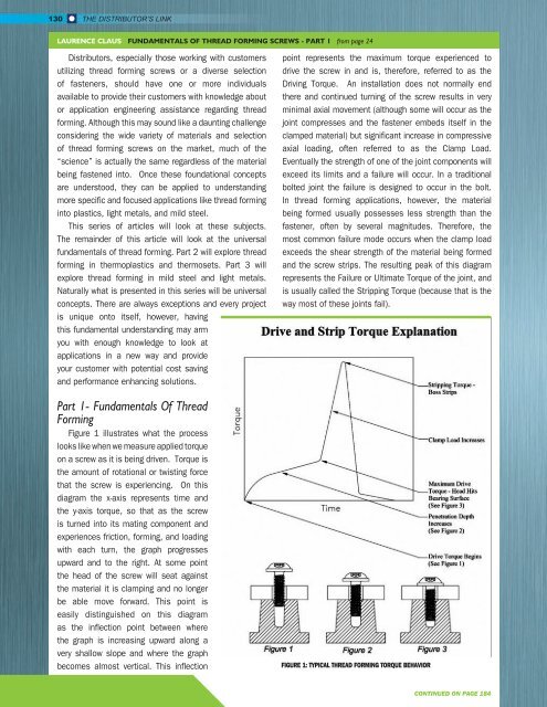
Figure 1 illustrates what the process<br />
looks like when we measure applied torque<br />
on a screw as it is being driven. Torque is<br />
the amount of rotational or twisting force<br />
that the screw is experiencing. On this<br />
diagram the x-axis represents time and<br />
the y-axis torque, so that as the screw<br />
is turned into its mating component and<br />
experiences friction, forming, and loading<br />
with each turn, the graph progresses<br />
upward and to the right. At some point<br />
the head of the screw will seat against<br />
the material it is clamping and no longer<br />
be able move forward. This point is<br />
easily distinguished on this diagram<br />
as the inflection point between where<br />
the graph is increasing upward along a<br />
very shallow slope and where the graph<br />
becomes almost vertical. This inflection<br />
point represents the maximum torque experienced to<br />
drive the screw in and is, therefore, referred to as the<br />
Driving Torque. An installation does not normally end<br />
there and continued turning of the screw results in very<br />
minimal axial movement (although some will occur as the<br />
joint compresses and the fastener embeds itself in the<br />
clamped material) but significant increase in compressive<br />
axial loading, often referred to as the Clamp Load.<br />
Eventually the strength of one of the joint components will<br />
exceed its limits and a failure will occur. In a traditional<br />
bolted joint the failure is designed to occur in the bolt.<br />
In thread forming applications, however, the material<br />
being formed usually possesses less strength than the<br />
fastener, often by several magnitudes. Therefore, the<br />
most common failure mode occurs when the clamp load<br />
exceeds the shear strength of the material being formed<br />
and the screw strips. The resulting peak of this diagram<br />
represents the Failure or Ultimate Torque of the joint, and<br />
is usually called the Stripping Torque (because that is the<br />
way most of these joints fail).<br />
FIGURE 1: TYPICAL THREAD FORMING TORQUE BEHAVIOR<br />
CONTINUED ON PAGE 184